
FTP-802S15 - Adapter / Network Card Planet - Free user manual and instructions
Find the device manual for free FTP-802S15 Planet in PDF.


| Product Type | Network Adapter / NIC |
| Model | FTP-802S15 |
| Brand | Planet |
| Interface | PCI Express (PCIe) |
| Data Transfer Rate | 10/100/1000 Mbps (Gigabit Ethernet) |
| Connector Type | RJ45 |
| Dimensions (approx.) | 120 mm x 70 mm x 15 mm |
| Weight (approx.) | 50 g |
| Power Supply | Via PCIe slot (3.3V / 12V) |
| Power Consumption | Less than 2.5 W |
| Compliance Standards | IEEE 802.3, 802.3u, 802.3ab |
| Auto-Negotiation | Yes |
| Auto MDI/MDIX | Yes |
| Jumbo Frame Support | Up to 9 KB |
| Operating Temperature | 0°C to 40°C |
| Storage Temperature | -20°C to 70°C |
| Humidity | 10% to 90% (non-condensing) |
| Supported OS | Windows, Linux, macOS |
| LED Indicators | Link/Activity, Speed |
| Maintenance | Keep connectors clean; avoid physical damage; use in ESD-safe environment. |
| Safety Precautions | Disconnect power before installation; handle with care to avoid static discharge. |
| Spare Parts / Repairability | No user-serviceable parts; replace unit if defective. |
Frequently Asked Questions - FTP-802S15 Planet
User questions about FTP-802S15 Planet
0 question about this device. Answer the ones you know or ask your own.
Ask a new question about this device
Download the instructions for your Adapter / Network Card in PDF format for free! Find your manual FTP-802S15 - Planet and take your electronic device back in hand. On this page are published all the documents necessary for the use of your device. FTP-802S15 by Planet.
USER MANUAL FTP-802S15 Planet
User's Manual
100Base-FX to 10/100Base-TX
PoE
Media Converter
FTP-80x
User's Manual
Trademarks
Copyright © PLANET Technology Corp. 2008.
Contents subject to revision without prior notice.
PLANET is a registered trademark of PLANET Technology Corp. The information in this manual is subject to change without notice. All other trademarks belong to their respective owners.
Disclaimer
PLANET Technology does not warrant that the hardware will work properly in all environments and applications, and makes no warranty and representation, either implied or expressed, with respect to the quality, performance, merchantability, or fitness for a particular purpose.
PLANET has made every effort to ensure that this User's Manual is accurate; PLANET disclaims liability for any inaccuracies or omissions that may have occurred.
Information in this User's Manual is subject to change without notice and does not represent a commitment on the part of PLANET. PLANET assumes no responsibility for any inaccuracies that may be contained in this User's Manual. PLANET makes no commitment to update or keep current the information in this User's Manual, and reserves the right to make improvements to this User's Manual and/or to the products described in this User's Manual, at any time without notice.
If you find information in this manual that is incorrect, misleading, or incomplete, we would appreciate your comments and suggestions.
FCC Warning
This equipment has been tested and found to comply with the regulations for a Class A digital device, pursuant to Part 15 of the FCC Rules. These limits are designed to provide reasonable protection against harmful interference when the equipment is operated in a commercial environment. This equipment generates, uses, and can radiate radio frequency energy and, if not installed and used in accordance with this user's guide, may cause harmful interference to radio communications. Operation of this equipment in a residential area is likely to cause harmful interference, in which case the user will be required to correct the interference at his own expense.
CE Mark Warning
This is a Class A product. In a domestic environment, this product may cause radio interference, in which case the user may be required to take adequate measures.
WEEE Warning

To avoid the potential effects on the environment and human health as a result of the presence of hazardous substances in electrical and electronic equipment, end users of electrical and electronic equipment should understand the meaning of the crossed-out wheeled bin symbol. Do not dispose of WEEE as unsorted municipal waste and have to collect such WEEE separately.
Revision
User's manual for PLANET 100Base-FX to 10/100Base-TX PoE Media Converter
Multi-mode: FTP-802
Single-mode: FTP-802S15
Rev 1.0 (March, 2008)
Part No. 2350-AA3540-000
Table Of Contents
- Overview ......6
- Model List ....7
- Checklist 7
- Product Outlook ....8
- Link Fault Pass through (LFP).... 10
- Installing the Converter 13
- PoE function 14
- LED indication 15
- Cable Connection Parameter 16
- FTP-80X Technical Specifications 17
APPENDIX A 18
A.1 Device's RJ-45 Pin Assignments ... 18
A.2 RJ-45 cable pin assignment ... 18
A.3 Fiber Optical Cable Connection Parameter 19
1. Overview
Thank you for purchasing PLANET FTP-80X family 10/100Mbps Ethernet Twisted pair to 100Base-FX Fiber-optic PoE Bridge Converter. This converter is used to convert one type media signal to other type equivalent that allows two type segments connect easily, efficiently and inexpensively. The converter provides Power over Ethernet power injector function which is able to drive one IEEE 802.3af compliant powered devices.
About the Power over Ethernet Injector
The FTP-80X is an IEEE 802.3af Power over Ethernet Injector that provide DC 48V over Ethernet cables. The FTP-80X IEEE 802.3af Power over Ethernet Injector inserts DC Voltage into Cat.5 cable, allowing the cable between the Injector (FTP-80X) and PoE PD (Powered Device) to transfer data and power simultaneously. The maximum distance between the Injector (FTP-80x) and PoE PD is 100 meters. With FTP-80x installed, it is combines the Ethernet digital data with power over the twisted pair cables as an IEEE 802.3af Power over Ethernet Injector. And the IEEE 802.3af Power over Ethernet splitter shall separate the digital data and the power into two outputs.
With IEEE 802.3af Power over Ethernet devices installed, the system administrator only have to use a single RJ-45 Ethernet cable to carries both power and data to each devices. Besides, to connect through FTP-80x and PoE PD, you could also have following benefit that, cost saving, easy for networking planning and higher reliability. What's more, upon any IEEE 802.3af devices installed, the FTP-80X or PD all can make the connection while migrating and the Ethernet digital packets, such as connecting the FTP-80X to an IEEE 802.3af complied devices, AP or IP Camera.
2. Model List
Your PoE Media Converter comes with two of the following models.
- FTP-802: on board SC / Multi-mode fiber connector, up to 2km
- FTP-802S15: on board SC / Single mode fiber connector, up to 15km
In the following sections, the term “FTP-80X” indicates the product family above.
3. Checklist
Your FTP-80X carton should contain the following items:
- 100Base-FX to 10/100Base-TX PoE Media Converter x 1
● AC-DC Power Adapter (Input: 48V DC, 0.4A max.) x 1 - User's Manual x 1
If any item is missing or damaged, please consult the dealer from whom you purchased your PoE Media Converter.
4. Product Outlook
Overview
The layout of FTP-802 is the same as for FTP-802S15
Rear Panel

TOP Panel

Bottom


Front Panel
Left View
There are one RJ-45 Twisted-Pair jack (Auto-MDI/MDI-X), one fiber-optic connector (vary by model) and four LED indicators.

Right View
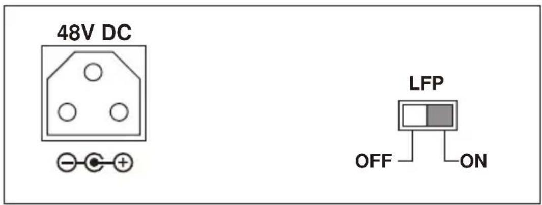
One DIP switch for Link Fault Pass Through (LFP) feature, "ON" to turn-on the LLCF and LLR detection. And "OFF" to turn-off this feature. Please refer to the following sections for more. Also one DC 48V power socket for the PoE Media Converter.
5. Link Fault Pass through (LFP)
The LFP function includes the Link Fault Pass Through function (LLCF/LLR) and the DIP Switch design. LLCF/LLR can immediately alarm administrators the problem of the link media and provide efficient solution to monitor the net. The DIP Switch provides disable or enable the LFP function.
LLCF (Link Loss Carry Forward) means when a device connected to the converter and the TP line loss the link, the converter's fiber will disconnect the link of transmit. LLR (Link Loss Return) means when a device connected to the converter and the fiber line loss the link, the converter's fiber will disconnect the link of transmit. Both can immediately alarm administrators the problem of the link media and provide efficient solution to monitor the net.
Link Loss Carry Forward (LLCF)
FTP-80X incorporates an LLCF function for troubleshooting a remote connection. When LFP function is enabled, the FL / TP ports do not transmit a link signal until they receive a link signal from the opposite port.
The diagram below shows a typical network configuration with a good link status using FTP-80X for remote connectivity.
![graph LR A["Management Station"] <--> B["Switch/Hub w/SNMP"] B <--> C["Media Converter"] C <--> D["LFP ONLFP ON"] D <--> E["Switch/Hub w/SNMP"] E <--> F["Management Station"] G["TP"] --> C H["Fiber Cable"] --> D I["● LED lit = established link ○ LED unlit = no link"]](/content/2026/05/1087069/images/90c7d9ac3409e9bba6c69e84d2ac0ae8cb8ed61363db266dfd4a81f810fd904a.jpg)
If the connection breaks, FTP-80X that link loss forward to the switch/hub that generates a trap to the management station.
The administrator can then determine the source of the problem.
![graph LR A["Management Station"] --> B["Switch/Hub w/SNMP"] B --> C["Media Converter"] C --> D["LFP ONLFP ON"] D --> E["Switch/Hub w/SNMP"] E --> F["Management Station"] C --> G["TP"] C --> H["Broken Fiber Cable"] D --> I["LED lit = established link ○ LED unlit = no link"]](/content/2026/05/1087069/images/3f2e5ff3175fbb4ae2449617e63e46cba2c8c21cacb204cee0486c92667c2b72.jpg)
* Units are shipped with the LFP function disable (OFF).
Link Loss Return (LLR)
The fiber ports of FTP-80X have been designed with an LLR function for troubleshooting a remote connection. LLR works in conjunction with LLCF.
When LFP function is enabled, the port's transmitter shuts down when its receiver fails to detect a valid receive link. LLR should only be enabled on one end of the link and is typically enabled on either the unmanaged or remote device.
The diagram below shows a typical network configuration with a good link status using FTP-80X for remote connectivity. Note that LLR and LLCF are enabled as indicated in the diagram.
![graph LR A["Management Station"] <--> B["Switch/Hub w/SNMP"] B <--> C["Media Converter"] C <--> D["LFP OFFLFP ON"] D <--> E["Switch/Hub"] E <--> F["Station"] G["Fiber Cable"] --> C G --> D style A fill:#ccc style B fill:#ccc style C fill:#ccc style D fill:#ccc style E fill:#ccc style F fill:#ccc not…](/content/2026/05/1087069/images/5bf095c3d905e6e2e378d79cec1c46832df5d541b81188b3ae0f74f14ed7d9e6.jpg)
If one of the optical conductors is bad (as shown in the diagram box below), the converter with LLR function will return a no-link condition to its link partner. With LLCF function also enabled, the no-link condition is carried forward to the switch/hub where a trap is generated to the management station, and the administrator can then determine the source of the loss.
![graph LR A["Management Station"] --> B["Switch/Hub w/SNMP"] B --> C["Media Converter"] C --> D["LFP ONLFP ON"] D --> E["Management Switch/Hub"] E --> F["Station"] C --> G["TP"] C --> H["PT"] C --> I["Broken Fiber"] D --> J["Link Loss Carried Forward"] D --> K["Link Loss Carried Forward"] D --> L["Li…](/content/2026/05/1087069/images/5937ec6551d2848cb22a82428dde73e2a37a83bc7293d01a0ee1d25f3a6f0379.jpg)

Note
LFP function is turn-off in default. This feature can also be turned on via the side DIP-switch. If you are not familiar with the network installation and for diagnostic purpose (i.e. check which end is broken), you can turn it on and reset the converter to make it take effect. Otherwise, please remain it in the default position.
6. Installing the Converter
Please follow these steps to install the PoE Media converter:
- Turn off the power of the device/station in a network to which the FTP-80X will be attached.
- Ensure that there is no activity in the network.
- Attach fiber cable from the FTP-80X to the fiber network. TX, RX must be paired at both ends.
- Attach a Cat. 5 UTP cable from the 10/100Base-TX network to the RJ-45 port on the FTP-80X.
- Connect the 48V DC power adapter to the FTP-80X and verify that the Power LED lights up.
- Turn on the power of the device/station, the TX Link and FX Link LEDs should light when all cables are attached.
![graph TD A["100Base-FX Fiber Network"] -->|TX| B["FTP-80X"] A -->|RX| B C["10/100Base-TX Cat. 5/5e TP Cable Network"] --> B](/content/2026/05/1087069/images/e1528c6e1da099bf3134865c17157df76e9e149ff3185d99cc35b125fb4cf84f.jpg)

Note
■ RJ-45/STP, UTP Cat 5, straight / crossover cable is accepted.
■ Please refer to section 9 for more about the wiring distance of your TP, Optic-fiber networks.
7. PoE function
FTP-80X and the IEEE 802.3af Injector / Splitter equipment installation:
Before your installation, it is recommended to check your network environment. If there is any IEEE 802.3af devices need to power on, the FTP-80X can provide you a way to supply power for this Ethernet device conveniently and easily. The FTP-80X equips with an AC-DC adapter with DC 48V input and injects this DC power into the pin of the twisted pair cable (pair 1, 2 and pair 3, 6).
If there is very difficult to find a power socket for AC-DC Adapter of your non-IEEE 802.3af networked device, the FTP-80X and POE-151S / 152S can provide you a way to supply DC power for this Ethernet device conveniently and easily.
For the places hard to find the power inlet, the FTP-80X provide the easiest way to power your Ethernet devices such as PLANET IEEE 802.3af Power over Ethernet Splitter (POE-151S / 152S) with Internet Camera (ICA-210) or Wireless Access Point (WAP-4060PE) installed in the wild rang place.
![graph LR A["Fiber Switch"] -->|Data| B["FTP-80x"] B -->|Data + Power| C["PoE Wireless AP"] B --> D["Power"] D --> E["Mobile Device"] style A fill:#cce5ff,stroke:#333 style B fill:#ffcccc,stroke:#333 style C fill:#ffcccc,stroke:#333 style D fill:#ffcccc,stroke:#333 style E fill:#ffcccc,stroke:#333](/content/2026/05/1087069/images/2255f1d1a9d555f26ec01ff4bac42a070e8c3d77ef739901b215749ba0f9d0d8.jpg)
8. LED indication
■ System
| LED Color Function | |
| PWR Green Lit: | Indicate the device is powered. |
■ 10/100 Base-TX Port
| LED Color Function | |||
| LNK/ACT | Green | Blink | Indicate that the Media Converter is actively sending or receiving data over that port. |
| Lit Indicate that the port is link up. | |||
| Off Indicate that the port is link down. | |||
| PoE in Use | Green | Lit | Indicate that the port is providing 48VDC to remote powered device. |
| Off | Indicate that the port is not providing 48VDC to remote powered device. | ||
■ 100 Base-FX SC Port
| LED Color Function | |||
| LNK/ACT | Green | Blink | Indicate that the Media Converter is actively sending or receiving data over that port. |
| Lit Indicate that the port is link up. | |||
| Off Indicate that the port is link down. | |||

Note
Fiber-optic Partner should be set to the correct mode according to this FDX indicator for optimal network performance.
9. Cable Connection Parameter
The limitations are as below:
| Duplex Connection Limitation (max.) | ||
| Twisted Pair | ||
| Half / Full | Node to NodeNode to Switch/Hub | 100 meters |
| Multi-Mode Converters | ||
| MM Half | Node to NodeNode to Switch | 412 meters |
| MM Full | Node to NodeNode to Switch | FTP-802: 2 kilometers |
| Single-Mode Converters | ||
| SM Full | Node to NodeNode to Switch | FTP-802S15: 15 kilometers |
10. FTP-80X Technical Specifications
The FTP-80X comes with the following standard features:
- Standard: IEEE 802.3u, 10/100Base-TX ,100Base-FX IEE E 802.3af Power over Ethernet
- Connectors:
■ One RJ-45 (Auto-MDI/MDI-X) Twisted Pair, EIA568 with PoE
■ One Fiber-optic, 1310nm wavelength, connector-type vary with model
● Data Transfer Rate: 10/100Mbps (TP), 100Mbps (FX)
- Duplex mode support: Full or half-duplex mode by Auto-Negotiation (TP)
● LED indicators: PWR, FX LNK/ACT, TX LNK/ACT, PoE in Use
● PoE Power Output: 48V DC, Max. 15.4 watts, 350mA
● Power Pin Assignment: 1/2(+), 3/6(-) / End-Span
● Power Supply: 48V DC, 0.4A, external AC-DC adapter
- Ambient Temperature: 0° to 50°C (operating)
• Humidity: 5% to 90% (non-condensing)
● Dimension: 26 x 70 x 97mm (H x W x D)
- Cable:
■ UTP: Cat 5 UTP cable
■ Fiber: MM: 50/125 μm or 62.5/125 μm optic fiber
■ Fiber: SM: 9/125 μm optic fiber
Connecting to Router, Bridge, or Switch, Hub, please refer to the device's Technical Manual.
APPENDIX A
A.1 Device's RJ-45 Pin Assignments
■ 10/100Mbps, 10/100Base-TX
| Contact MDI | MDI-X | |
| 1 1 (TX +) | 3 | |
| 2 2 (TX -) | 6 | |
| 3 3 (RX +) | 1 | |
| 6 6 (RX -) | 2 | |
| 4, 5, 7, 8 Not used | used Not used |
Implicit implementation of the crossover function within a twisted-pair cable, or at a wiring panel, while not expressly forbidden, is beyond the scope of this standard.
A.2 RJ-45 cable pin assignment
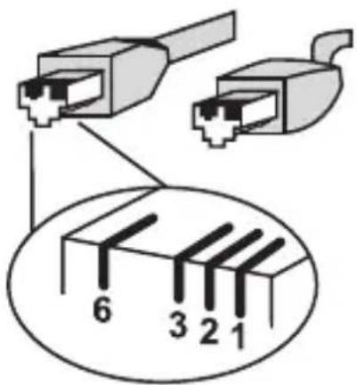
There are 8 wires on a standard UTP/STP cable and each wire is color-coded. The following shows the pin allocation and color of straight cable and crossover cable connection:
| Straight Cable | SIDE 1 | SIDE 2 | |
| 1 2 3 4 5 6 7 8 1 2 3 4 5 6 7 8 | SIDE 1 | 1 = White/Orange 2 = Orange 3 = White/Green 4 = Blue 5 = White/Blue 6 = Green 7 = White/Brown 8 = Brown | 1 = White/Orange 2 = Orange 3 = White/Green 4 = Blue 5 = White/Blue 6 = Green 7 = White/Brown 8 = Brown |
| Cross Over Cable | SIDE 1 | SIDE 2 | |
| 1 2 3 4 5 6 7 8 1 2 3 4 5 6 7 8 | SIDE 1 | 1 = White/Orange 2 = Orange 3 = White/Green 4 = Blue 5 = White/Blue 6 = Green 7 = White/Brown 8 = Brown | 1 = White/Green 2 = Green 3 = White/Orange 4 = Blue 5 = White/Blue 6 = Orange 7 = White/Brown 8 = Brown |
Figure A-1: Straight-Through and Crossover Cable
Please make sure your connected cables are with same pin assignment and color as above picture before deploying the cables into your network.
A.3 Fiber Optical Cable Connection Parameter
The wiring details are as below:
■ Fiber Optical patch Cables:
| Standard Fiber Type Cable Specification | |
| 100Base-FX(1310nm) | Multi-mode 50/125μm or 62.5/125μm |
| 100Base-FX(1310nm) | Single-mode 9/125μm |
EC Declaration of Conformity
For the following equipment:
*Type of Product : 100Base-FX to 10/100Base-TX PoE Media Converter
*Model Number : FTP-802 / FTP-802S15
* Produced by:
Manufacturer's Name : Planet Technology Corp.
Manufacturer's Address : 11F, No. 96, Min Chuan Road, Hsin Tien
Taipei, Taiwan, R. O.C.
is herewith confirmed to comply with the requirements set out in the Council Directive on the Approximation of the Laws of the Member States relating to Electromagnetic Compatibility Directive on (89/336/EEC).
For the evaluation regarding the EMC, the following standards were applied:
Emission EN 55022 (1994 + A1:1995 + A2:1997
Cla ss A)
Harmonic EN 61000-3-2 (2000)
Flicker EN 61000-3-3 (1995 + A1:2001)
Immunity EN 55024 (1998)
ESD IEC 61000-4-2 (1995 + A1:1998 + A2:2000)
RS IEC 61000-4-3 (1995 + A1:1998 + A2:2000)
EFT/ Burst IEC 61000-4-4 (1995 + A1:2000)
Surge IEC 61000-4-5 (1995 + A1:2000)
CS IEC 61000-4-6 (1996 + A1:2000)
Magnetic Field IEC 61000-4-8 (1993 + A1:2000)
Voltage Disp IEC 61000-4-11 (1994 + A1:2000)
Responsible for marking this declaration if the:
☑ Manufacturer ☐ Authorized representative established within the EU
Authorized representative established within the EU (if applicable):
Company Name: Planet Technology Corp.
Company Address: 11F, No.96, Min Chuan Road, Hsin Tien, Taipei, Taiwan, R.O.C
Person responsible for making this declaration
Name, Surname Kent Kang
Position / Title : Product Manager
Taiwan Place
15, March., 2008 Date

Legal Signature
PLANET TECHNOLOGY CORPORATION
www.planet.com.tw

- 100BASE-FX TO 10/100BASE-TX
- POE
- MEDIA CONVERTER
- TRADEMARKS
- DISCLAIMER
- FCC WARNING
- CE MARK WARNING
- WEEE WARNING
- REVISION
- TABLE OF CONTENTS
- APPENDIX A 18
- OVERVIEW
- ABOUT THE POWER OVER ETHERNET INJECTOR
- MODEL LIST
- CHECKLIST
- PRODUCT OUTLOOK
- LEFT VIEW
- RIGHT VIEW
- LINK FAULT PASS THROUGH (LFP)
- LINK LOSS CARRY FORWARD (LLCF)
- LINK LOSS RETURN (LLR)
- INSTALLING THE CONVERTER
- POE FUNCTION
- FTP-80X AND THE IEEE 802.3AF INJECTOR / SPLITTER EQUIPMENT INSTALLATION
- LED INDICATION
- SYSTEM
- 10/100 BASE-TX PORT
- 100 BASE-FX SC PORT
- CABLE CONNECTION PARAMETER
- FTP-80X TECHNICAL SPECIFICATIONS
- APPENDIX A
- A.1 DEVICE'S RJ-45 PIN ASSIGNMENTS
- A.2 RJ-45 CABLE PIN ASSIGNMENT
- A.3 FIBER OPTICAL CABLE CONNECTION PARAMETER
- FIBER OPTICAL PATCH CABLES
- EC DECLARATION OF CONFORMITY
- PLANET TECHNOLOGY CORPORATION
Brand : Planet
Model : FTP-802S15
Category : Adapter / Network Card