
ARD-020 - Electronic board Steren - Free user manual and instructions
Find the device manual for free ARD-020 Steren in PDF.


| Product Type | PCB compatible with Arduino Leonardo |
| Microcontroller | Atmel MEGA32U4 |
| Input Voltage | 5-12 V DC |
| Operating Frequency | 16 MHz |
| Analog Input Ports | 12 |
| Digital Input/Output Ports | 20 (including PWM) |
| Flash Memory | 256 kB |
| SRAM | 2.5 kB |
| EEPROM | 1 kB |
| Bootloader | STK500v2 |
| PWM Output | Yes |
| Output Voltage | 5 V DC |
| Reset Switch | Yes |
| PC Interface | USB |
| Software | Arduino IDE (free) |
| Compatibility | Arduino Leonardo shields and code |
| Warranty | 1 year from date of purchase |
Frequently Asked Questions - ARD-020 Steren
User questions about ARD-020 Steren
0 question about this device. Answer the ones you know or ask your own.
Ask a new question about this device
Download the instructions for your Electronic board in PDF format for free! Find your manual ARD-020 - Steren and take your electronic device back in hand. On this page are published all the documents necessary for the use of your device. ARD-020 by Steren.
USER MANUAL ARD-020 Steren
natural_image
Illustration of a printed circuit board with various electronic components and connectors (no readable text or symbols)natural_image
Close-up of a printed circuit board with electronic components and a red LED indicator (no readable text or symbols)Programa
Programa
line
| Tiempo | Voltaje | | ------ | ------- | | 0 | 0 | | 1 | 1 | | 2 | 0 | | 3 | 1 | | 4 | 0 | | 5 | 1 | | 6 | 0 | | 7 | 1 | | 8 | 0 | | 9 | 1 | | 10 | 0 | | 11 | 1 | | 12 | 0 | | 13 | 1 | | 14 | 0 | | 15 | 1 | | 16 | 0 | | 17 | 1 | | 18 | 0 | | 19 | 1 | | 20 | 0 | | 21 | 1 | | 22 | 0 | | 23 | 1 | | 24 | 0 | | 25 | 1 | | 26 | 0 | | 27 | 1 | | 28 | 0 | | 29 | 1 | | 30 | 0 | | 31 | 1 | | 32 | 0 | | 33 | 1 | | 34 | 0 | | 35 | 1 | | 36 | 0 | | 37 | 1 | | 38 | 0 | | 39 | 1 | | 40 | 0 | | 41 | 1 | | 42 | 0 | | 43 | 1 | | 44 | 0 | | 45 | 1 | | 46 | 0 | | 47 | 1 | | 48 | 0 | | 49 | 1 | | 50 | 0 | | 51 | 1 | | 52 | 0 | | 53 | 1 | | 54 | 0 | | 55 | 1 | | 56 | 0 | | 57 | 1 | | 58 | 0 | | 59 | 1 | | 60 | 0 | | 61 | 1 | | 62 | 0 | | 63 | 1 | | 64 | 0 | | 65 | 1 | | 66 | 0 | | 67 | 1 | | 68 | 0 | | 69 | 1 | | 70 | 0 | | 71 | 1 | | 72 | 0 | | 73 | 1 | | 74 | 0 | | 75 | 1 | | 76 | 0 | | 77 | 1 | | 78 | 0 | | 79 | 1 | | 80 | 0 | | 81 | 1 | | 82 | 0 | | 83 | 1 | | 84 | 0 | | 85 | 1 | | 86 | 0 | | 87 | 1 | | 88 | 0 | | 89 | 1 | | 90 | 0 | | 91 | 1 | | 92 | 0 | | 93 | 1 | | 94 | 0 | | 95 | 1 | | 96 | 0 | | 97 | 1 | | 98 | 0 | | 99 | 1 | | Note: The 'Voltaje' values are estimated based on the provided code. The 'Voltaje efectivo' is not explicitly labeled in the code. There is only one data series in this case. The 'Tiempo' axis is labeled as 'Tiempo'.Instruction manual
1014z
V0.1
PCB COMPATIBLE WITH ARDUINO LEONARDO
ARD-020
Thank You on purchasing your new Steren product.
This manual includes all the feature operations and troubleshooting necessary to install and operate your new Steren's PCB compatible with Arduino Leonardo.
Please review this manual thoroughly to ensure proper installation and operation of this product. For support, shopping, and everything new at Steren, visit our website:
www.steren.com

The instructions of this manual are for reference about the product. There may be differences due to updates.
Please check our website (www.steren.com) to obtain the latest version of the instruction manual.
IMPORTANT
- Keep device out of the reach of children.
- Do not expose to extreme temperatures.
- Do not use or store the equipment near wet places.
- Avoid dropping the unit as this may cause damage.
- Do not place the device or accessories on surfaces that are tilted, unstable or subject to vibration.
- Do not put heavy objects on the device or accessories.
- Do not expose the device or accessories to dust, smoke or steam.
HIGHLIGHTS
- The PCB with MEGA32U4 Atmel micro controller allows you to use all input and output ports, helping to students and hobbyists not to worry about control stage.
- The communication and programming interface is performed using free software (used by Arduino) and cab be connected to the PC through the USB port. It has an ISCP port.
GETTING STARTED WITH ARDUINO
This manual will help you understand what it is and how Arduino works to begin to build your own electronic projects.
What is Arduino?
Arduino is an electronic open platform for prototype creation based on flexible and easy to use software and hardware.
It has everything you need for basic use soldered on a small circuit. The plate contains the microcontroller and provides convenient access to inputs and outputs. Entries are devices such as sensors (sensors, thermometers, gyroscopes, etc.) and elements of human interface (buttons, switches and knobs). The outputs are electronic components that you want to be able to control, such as lights, displays, motors and servos. A microcontroller has all the basic parts of a computer (processor, memory, input/output pins) on a single chip and runs the software that is loaded on it from a computer, which allows you to manipulate the results based on data it receives at the inputs.
Arduino is open source. As open source hardware, schemes for Arduino are available to anyone for free, if you want to buy electronic components and a plate and build your own Arduino.
There is a huge range of projects that need a microcontroller. A simple project could be something like a LED light strip. A basic circuit can turn the LED lights on, but in order to get to change color and patterns you will need a microcontroller. More complex projects might be a robotic arm, a holographic LED display or cleanable auto cat litter box.
You need to download an additional hardware to set the circuit. You will need a USB cable for programming it and if you want to be able to run your project when you are not near your computer, you will need an adapter current AC-DC or battery and cable. You will find these components on Steren.
Shields
A shield is an additional circuit to your Arduino board. Usually, a shield is placed over the base Arduino, connects with its I/O pins and allows the Arduino specialize by adding additional capabilities, or providing a more convenient interface for your project. For example, a shield could allow to integrate a GPS chip or an SD card to your project. Some shields can be stacked one on top of the other, to add several additional functions.
ARDUINO PROGRAMMING
- Download the Arduino development environment and install it on your PC. The environment is available for Windows, Mac and Linux and includes everything you need to begin programming.
- Connect the Arduino to the computer and (if you are using a Windows machine) wait for the drivers to be installed.
- When you start using the Arduino editor, you need to configure in the Tools menu at the top of the editor, the card and serial port options; in the first, select the bought Arduino model. In the second select the port at which the Arduino is connected to. If you have questions about this port, simply disconnect the Arduino and the option that disappears is your port.

Finally, you are ready to write programs (the Arduino editor refers to them as "sketches") for your project. You'll need some familiarity with C++programming, variables, functions, "if" statements and loops, but the Arduino sketches tend to be simpler.
SKETCHES
The best way to learn programming Arduino is through the example sketches included in the Arduino IDE. These are located in the file menu > examples and many examples can be found on the Internet.
Once you have written a sketch, simply click the load button and it will be sent to your Arduino board. The microcontroller will restart and run your sketch until it gets a different one.
Below you will find small step by step projects.
1. Flashing
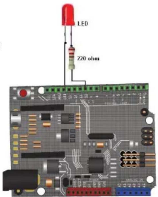
It is a basic exercise that shows how to turn a LED that is connected to PIN 13 of Arduino configured as output. Turn on and off time is 1 second.
Plot and scheme
Since Arduino PIN 13 has an internal resistance, the red LED is placed without resistance in series; if you place the led in another output you should place a resistance of between 220 and 500 ohms, depending on the power LED consumption.

The connection to be carried out in this case is to 10 PIN output.
Program
/*
 * Intermittent
 *
 * Basic example with Arduino. Switching on and off of a LED
 * with a cadence of 1 s using the 13 PIN as output
 * is not necessary to use a resistor for LED
 * exit 13 Arduino has it built-in.
 *
 * http://www.arduino.cc/en/Tutorial/Blink
 */
int ledPin = 13; // Definition of the PIN 13 output
void setup() //Configuration
{
    pinMode(ledPin, OUTPUT); // designates the PIN 13 digital output
}
void loop() // operating loop
{
    digitalWrite(ledPin, HIGH); // activates the LED
    delay (1000); // 1 s wait (on-time)
    digitalWrite(ledPin, LOW); // disables the LED
    delay (1000); // 1 s wait (off-time)
}
2. Alarm
When you press the button (input 5 to '0'), output 13 turns on and shuts off intermittently.
How it works:
When the I5 = 1 then O13 = 0
When the I5 = 0 then O13 = 0-1 (intermittent 200,200 ms)

Program
int ledPin = 13; // choose the PIN for LED
int Nifne = 5; // choose the input pin (for a pushbutton)
int val = 0; // variable for reading the pin status
void setup() {
    pinMode(ledPin, OUTPUT); // declare LED as output
    pinMode(inPin, INPUT); // declare pushbutton as input
}
void loop() {
    val = digitalRead (Nifne); // reads input value
    if(val == HIGH) { // check if the value read is "1" (button pressed)
    digitalWrite(ledPin, LOW); // set the LED to OFF
} else {
    digitalWrite(ledPin, LOW); // the LED blinks
    delay (200);
    digitalWrite(ledPin, HIGH);
    delay (200);
}
3. Basic 3 LEDs sequence
It turns on and off 3 LEDs placed in the 6, 7 and 8 outputs (PIN 6 PIN 7 and PIN 8) with a cadence of 200 ms. Assigned to each LED are ledPin1, ledPin2 and ledPin3 variables.

Program
Switching on and off of 3 LEDs
int ledPin1 = 6; // Defines the LEDs outputs
int ledPin2 = 7;
int ledPin3 = 8;
void setup() { // set the outputs
pinMode(ledPin1, OUTPUT); // declare LEDs as outputs
pinMode(ledPin2, OUTPUT);
pinMode(ledPin3, OUTPUT);
digitalWrite(ledPin1, LOW); // Turn off the LEDs
digitalWrite (ledPin2, LOW);
digitalWrite (ledPin3, LOW);
}
void loop() { //work loop
digitalWrite(ledPin1, HIGH); // turn off and on the LEDs lights every 200 ms
delay (200);
digitalWrite (ledPin1, LOW);
digitalWrite (ledPin2, HIGH);
delay (200);
digitalWrite (ledPin2, LOW);
digitalWrite (ledPin3, HIGH);
delay (200);
digitalWrite (ledPin3, LOW);
}
4. Counter
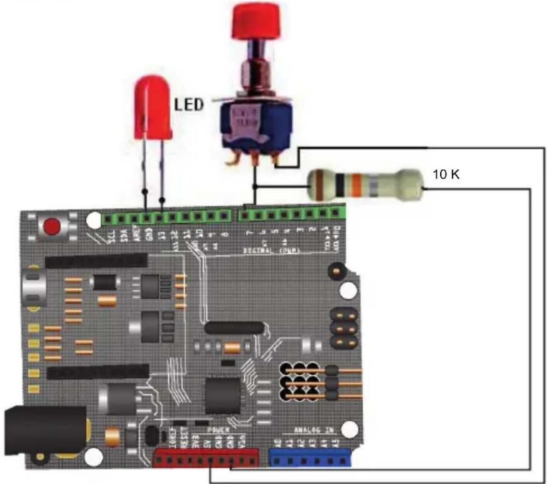
It counts the times a button connected to Arduino input 7 is pressed whenever we have we light the LED connected at output 13. The value of the variable that stores the number of pulses generated is sent to the PC so that it is displayed on the screen.
Program counter
/* Detects if connected to the input jack 7 button has been pressed and LED lights up
* Send the value of the variable 'Counter' account via serial port to the PC.
*
*/
int LED = 13;
int Button = 7;
int value = 0;
int counter = 0;
int buttonlaststate = 0;
void setup()
{
Serial.begin(9600); // Configures transmission speed to 9600
pinMode(LED, OUTPUT); // Initializes as a digital output pin 13
pinMode(Boton, INPUT); // initializes as a digital input the 7
digitalWrite(Boton,HIGH); // Enable internal resistance Pull-up from PIN7
}
void loop()
{
value = digitalRead(Boton); // Reads the digital input pin 7 value
digitalWrite(LED, !valor); // Write in the output the read denied value
if(value != int buttonlaststate){
if(value == 1){
counter++;
Serial.print(counter);
Serial.write(10);
Serial.write(13);
}}
int buttonlaststate = value;
}
We could avoid the resistance placed at the button if the internal resistance of PIN7 is enabled, in this case the circuit would be as follows:

The program in this case would be very similar to the previous. Note that now when the button is pressed we introduce an “=” at PIN7, therefore, if you want to start the PIN13 output, you should write in it the value read from the denied button, i.e. “!value”.
Modifi ed counter program
/* Detects if connected to the input jack 7 button has been pressed and LED lights up
* Send the value of the variable 'Counter' account via serial port to the PC.
/*
int LED = 13;
int Button = 7;
int value = 0;
int counter = 0;
int buttonlaststate = 0;
void setup()
{
Serial.begin(9600); // Confi gures transmission speed to 9600
pinMode(LED, OUTPUT); // Initializes as a digital output pin 13
pinMode(Boton, INPUT); // Initializes as a digital input the 7
digitalWrite(Button,HIGH); // Enable internal resistance Pull-up from PIN7
}
void loop()
{
valor = digitalRead(Button); // Reads the digital input pin 7 value digitalWrite(LED, !value); // (Write in the output the read denied value if(value != int buttonlaststate){
if(value == 1){
counter++;
Serial.print(counter);
Serial.write(10);
Serial.write(13);
}}
int buttonlaststate = value;
}
5. Analog input
It set up the pin 5 as analog input and sends the read value to your PC to view it.

Program
/* Analog input */
int potPin = 5; // Selects the input PIN to put the potentiometer
int val = 0; // variable to store the value read from the analog input
void setup() {
Serial.begin(9600);
}
void loop() {
val = analogRead(potPin); // Reads the value from the input analog channel
Serial.print(val); // Sends to the PC the read analog value and displays it on screen
Serial.write(10);
delay(100);
}
6. DC motor control using a transistor
With this example we are going to control the speed of a DC motor using a BD137 transistor. Uses the possibility of sending a PWM signal to one of the outputs set up as analog.

Please note that the motor must be low power for two reasons: first because if we feed testing from USB connector must not pull too much current from the computer and second, because the transistor is current limited.
1N4001 diode is positioned as protection to prevent that the reverse currents created in the motor winding could damage the transistor.
line
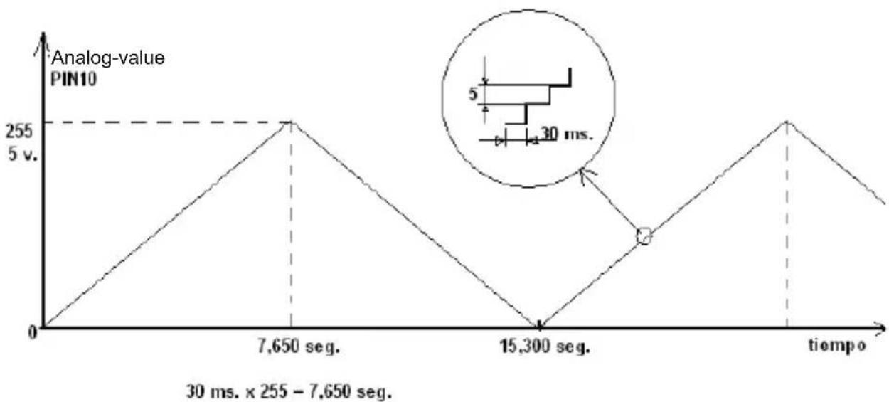
| tiempo | Analog-value | | ---------- | ------------ | | 7,650 seg. | 255 | | 15,300 seg. | 0 |The tension that we are going to pull from output 10 (analog type PWM) will vary on way to ramp up and down cyclically. We get this effect with a structure for type:
for(value = 0; value <= 255; value += 5) (ascending)
for(value = 255; value >=0; value -=5) (descending)
Note that increases in the voltage value range from 5 at 5 and we have to consider that 0v equals 0 and 5v is equivalent to 255.
Program
int value = 0; // a variable that contains the value to get analog input terminal
int motor = 10; // motor connected to PIN 10
void setup() { // Not necessary
void loop() {
for(value = 0; value <= 255; value += 5) {
// generates a ramp of voltage from 0 to 255, i.e. from 0 to 5v
analogWrite (motor, value);
delay (30); // wait 30 ms to make the effect visible
}
for(value = 255; value >= 0; value -= 5) {
// a down ramp from 255 to 0 voltage is generated that is 5 to 0v
analogWrite (motor, value);
delay (30);
}
Installation variant: using a potentiometer as speed control.
To control the speed to our liking, i.e. using a potentiometer which is placed in one of the analog inputs and based on the value that is read at the input, so the motor rotates more or less fast.
Program
int value = 0; // a variable that contains the value to get analog input read int motor = 10; // motor connected to PIN 10
int potentiometer = 0 ; // Set the analogue input
void setup(){ // Not necessary
void loop(){
value = analogRead (potentiometer); // reads the value of the analog input and allocates val
analogWrite (motor, value); // The read value is sent to the analog output 0 delay (30); // wait 30 ms to make visible the effect
}

7. DC motor control using a L293D driver
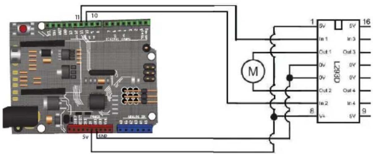
With this application we will move a DC motor using a power IC, specific for these applications. The circuit you can move up to two motors, we'll only do it with one.
In this Assembly, we can move the motor in both rotation directions, which we couldn't with the previous assembly.
It will function as the first approach of the previous motor, i.e., let's create a power surge and a descent ramp so motor change speed in automatic mode.
DC motor control or driver:
The two parameters that we want to control of a DC motor is its speed and its rotation direction. The direction is controlled by changing the polarity. On the other hand, for its speed, we must use modulation technique for PWM-pulse width.
Here are some graphs showing the relationship between the pulse (PWM) signal and the effective voltage:

line
| Time | Voltage | |------|---------| | 0 | Low | | 1 | High | | 2 | Low | | 3 | High | | 4 | Low | | 5 | High | | 6 | Low | | 7 | High |When the pulse is active is half of the period of the signal or duty cycle parameter is 50%, the effective voltage is half of the total input voltage.

line
| Time | Voltage | |------|---------| | 0 | Low | | 1 | High | | 2 | Low | | 3 | High | | 4 | Low | | 5 | High | | 6 | Low | | 7 | High |When the duty cycle is reduced to 25%, the effective voltage is a quarter of the total input voltage. Then the motor speed decreases.
Thus, by controlling the duty cycle or while the pulse is active (frequency), we can control the DC motor speed.
A way to perform this check on Arduino, is using the PWM analog output.
You should remembered that the PWM output signal (pins 9, 10) is a constant frequency signal (30769 Hz) and that only allows us to change the “duty cycle” or the time that the pulse is active (on) or inactive (off), using the analogWrite() function.
The other way is generating PWM signals using the microprocessor capability through the function digitalWrite ().
If you want to simultaneously control the speed and direction of a motor, we need to use an integrated circuit or chip, called in general, as “H bridge”, for example the L293D.
Chip L293D/B (H-bridge):
It is an integrated circuit or chip that can be used to simultaneously control the speed and direction of two DC motors (containing two H bridges). The difference between L393D and L293B model is that the first comes with protection diodes which avoid damage caused by the voltage spikes that the motor can cause.

It contains 4 digital pins (2, 7, 10, 15) to control the motor direction.
The “enable” (1, 9) pins support as input a PWM signal and it are used to control the speed of the motors using pulse width modulation technique.
The motors are connected between pins 3, 6, 11 or 14. The Vss voltage is to feed or give power to the motor.
Basic installation: Simple Control of an motor with the L293 CI at constant speed
First we will just show the speed of a DC motor control through the L293D integrated. So we set the direction control PIN to 5v and 0v, in such a way that it will only turn in one direction. If we want to change direction, it will only be necessary to change the polarization.
Program
Simple control of an motor with the L293 CI at constant speed
int motorpin = 10; // Output analog PWM PIN
void setup() {}
void loop() {
analogWrite(motorpin, 125); // activates the motor at a constant speed
delay (100); // wait 100 ms for the next reading
}

- Motor control: variable speed and variable rotation
Program
Motor control with L293D driver
int value = 0; // a variable that contains the value
int motorFowards = 10; // Motor forward -> PIN 10
int motorBackwards = 11; // Motor recoil -> PIN 11

void setup() {} // Not necessary
void loop() {
    analogWrite(motorBackwards, 0); // Motor forward... raises the speed
    for(value = 0; value <= 255; value += 5) {
    analogWrite (motorFowards, value);
    delay (30);
    }
    for(value = 255; value >= 0; value -= 5) { // forward motor... lowers the speed
    analogWrite (motorFowards, value);
    delay (30);
    }
    analogWrite(motorFowards, 0); // Motor back... raises the speed
    for(value = 0; value <= 255; value += 5) {
    analogWrite (motor motorBackwards, value);
    delay (30);
    }
    for(value = 255; value >= 0; value -= 5) { // motor backwards... lowers speed }
    analogWrite (motorBackwards, value);
    delay (30);
    }
}
9. Use a relay to turn on 120 V devices
This example shows how to power a 120-Volt alternating current (AC) light bulb through a circuit of 5 V DC (DC) ruled by the Arduino. It can be used with any other circuit of 120 V, with a maximum of 10 A (with the relay of the example).
What is a relay?
The relay is an electromechanical device that functions as a switch controlled by an electrical circuit in which, by means of an electromagnet, actuates a set of one or more contacts that allow open or close other independent electrical circuits.
From here extract important information: we can separate two circuits in such a way that they work with different voltages. One to 5 V (Arduino) and another 120 v (the bulb).
As shown in the diagram below, there are two circuits. Black wiring operates at 5 V DC and the red one at 120V AC.

Program
/*
It turns on and off a 220 V light bulb every 2 seconds, using,
a relay connected to the Arduino PIN 8
*/
int relayPin = 8; // PIN to which the relay is connected
void setup() {
    pinMode (relayPin, OUTPUT);
}
void loop() {
    digitalWrite(relayPin, HIGH); // Power
    delay (2000);
    digitalWrite(relayPin, LOW); // Shutdown
    delay (2000);
}
SPECIFICATIONS
Micro controller: MEGA32U4
Input: 5-12 V ---
Operational frequency: 16 MHz
Analogue input ports: 12
Digital input / output ports: 20 (including PWM ports)
Flash memory capacity: 256 kB
SRAM: 2.5 kB
EEPROM: 1 kB
Boot loader: STK500v2
PWM output: Yes
Voltage output: 5 V ---
Switch Reset: Yes
PC interface: USB
Software: Arduino

Product design and specifications are subject to change, without notice.
Product: PCB compatible with Arduino Leonardo
Part number: ARD-020
Brand: Steren
WARRANTY
This Steren product is warranted under normal usage against defects in workmanship and materials to the original purchaser for one year from the date of purchase.
CONDITIONS
- This warranty card with all the required information, invoice, product box or package, and product, must be presented when warranty service is required.
- If the product is in the warranty time, the company will repair it free of charge.
- The repairing time will not exceed 30 natural days, from the day the claim was received.
- Steren sell parts, components, consumables and accessories to customer, as well as warranty service, at any of the addresses mentioned later.
THIS WARRANTY IS VOID IN THE NEXT CASES:
If the product has been damaged by an accident, acts of God, mishandling, leaky batteries, failure to follow enclosed instructions, improper repair by unauthorized personnel, improper safe keeping, among others.
a) The consumer can also claim the warranty service in the purchase establishment. b) If you lose the warranty card, we can reissue it, if you show the invoice or purchase ticket.
RETAILER INFORMATION
Name of the retailer
Address
Product ____
Brand
Part number ____
Serial number
Date of delivery ____

In case your product fails or have questions, please contact your nearest dealer. If you are in Mexico, please call to our Call Center.
01 800 500 9000

STEREN
Help us to improve this instruction manual, call us:

01800 500 9000
Customer Service Center
www.steren.com
- PCB COMPATIBLE WITH ARDUINO LEONARDO
- IMPORTANT
- HIGHLIGHTS
- GETTING STARTED WITH ARDUINO
- What is Arduino?
- Shields
- ARDUINO PROGRAMMING
- SKETCHES
- Flashing
- Plot and scheme
- Alarm
- How it works:
- Basic 3 LEDs sequence
- Program
- Counter
- Modifi ed counter program
- Analog input
- DC motor control using a transistor
- DC motor control using a L293D driver
- DC motor control or driver:
- Chip L293D/B (H-bridge):
- Basic installation: Simple Control of an motor with the L293 CI at constant speed
- Use a relay to turn on 120 V devices
- What is a relay?
- SPECIFICATIONS
- WARRANTY
- CONDITIONS
- THIS WARRANTY IS VOID IN THE NEXT CASES:
- RETAILER INFORMATION
- STEREN
Brand : Steren
Model : ARD-020
Category : Electronic board