
VTG48A - Beacon light Epcom - Free user manual and instructions
Find the device manual for free VTG48A Epcom in PDF.


| Product Type | Emergency Warning Lightbar |
| Model | VTG48A (12+ Series Vantage) |
| Length | 48 inches |
| Height | 2.5 inches |
| Width | 11 inches |
| Voltage | 12-24 VDC |
| Current Draw (Single Color LED Module) | 0.45 A avg. @ 12.8 VDC |
| Current Draw (Dual Color LED Module) | 0.90 A avg. @ 12.8 VDC |
| Current Draw (LED STT pair) | 0.25 A avg. @ 12.8 VDC |
| Current Draw (LED AL, TD, WL pair) | 1.80 A avg. @ 12.8 VDC |
| Number of Flash Patterns | 48 |
| Housing Material | Aluminum |
| Lens Material | Polycarbonate |
| Mounting Options | Permanent mount or gutter mount (with optional roof kit) |
| Cleaning Instructions | Clean with soap and water or lens polish using a soft cloth. Do not use solvents or high-pressure washers. |
| Safety Warnings | High intensity LEDs - avoid direct eye exposure. Proper grounding required. Install per manual. |
| Warranty | 60 months from date of purchase (limited) |
| Replacement Parts Available | Lenses, LED modules, cables, touch pads, junction box, mounting feet |
| Compliance | SAE J595, California Title 13, ECE R65 (varies by pattern) |
Frequently Asked Questions - VTG48A Epcom
User questions about VTG48A Epcom
0 question about this device. Answer the ones you know or ask your own.
Ask a new question about this device
Download the instructions for your Beacon light in PDF format for free! Find your manual VTG48A - Epcom and take your electronic device back in hand. On this page are published all the documents necessary for the use of your device. VTG48A by Epcom.
USER MANUAL VTG48A Epcom
Installation and Operation Instructions 12+ Series Vantage™ Lightbars

Introduction:
12+ Series Lightbars are versatile and powerful warning devices suitable for a range of vehicle types and duties. There are numerous options and lengths available. The lightbars can either be mounted permanently to the vehicle or mounted using an optional roof mounting kit.
The 12+ Series Lightbar features a durable aluminu dules: Warning modules, Stop-Tail-Turn modules, and white Alley/Takedown/Worklight modules.
Unpacking and Pre-Installation:
Carefully remove the lightbar and place it on a flat surface. Examine the unit for transit damage and locate all parts. If damage is found or parts are missing, contact the transit company. Do not use damaged or broken parts.
Ensure the lightbar voltage is compatible with the planned installation.
IMPORTANT! Read all instructions before installing and using. Installer: This manual must be delivered to the end user. This manual assumes installation by a suitably qualified Automotive Technician.

Do not install and/or operate this safety product unless you have read and understand the safety information contained in this manual.
- Proper installation combined with operator training in the use, care and maintenance of emergency warning devices are essential to ensure the safety of emergency personnel and the public.
- Emergency warning devices often require high electrical voltages and/or currents. Exercise caution when working with live electrical connections.
- This product must be properly grounded. Inadequate grounding and/or shorting of electrical connections can cause high current arcing, which can cause personal injury and/or severe vehicle damage, including fire.
- Proper placement and installation is vital to the performance of this warning device. Install this product so that output performance of the system is maximized and the controls are placed within convenient reach of the operator so that s/he can operate the system without losing eye contact with the roadway.
- It is the responsibility of the vehicle operator to ensure daily that all features of this product work correctly. In use, the vehicle operator should ensure the projection of the warning signal is not blocked by vehicle components (i.e., open trunks or compartment doors), people, vehicles or other obstructions.
- The use of this or any other warning device does not ensure all drivers can or will observe or react to an emergency warning signal. Never take the right-of-way for granted. It is your responsibility to be sure you can proceed safely before entering an intersection, drive against traffic, respond at a high rate of speed, or walk on or around traffic lanes.
- This equipment is intended for use by authorized personnel only. The user is responsible for understanding and obeying all laws regarding emergency warning devices. Therefore, the user should check all applicable city, state, and federal laws and regulations. The manufacturer assumes no liability for any loss resulting from the use of this warning device.
- This product may contain high intensity LEDs staring directly into these lights could result in temporary and/or permanent vision impairment.

WARNING!
Failure to install or use this product according to manufacturer's recommendations may result in property damage, serious bodily/personal injury, and/or death to you and those you are seeking to protect!
Specifications:
Length.....48",54",60",72"
Height.....2.5" Width: 11"
Voltage.....12-24VDC
Current Draw......Single Color LED Module = 0.45A Avg. @ 12.8VDC
Dual Color LED Module = 0.90A Avg. @ 12.8VDC
LED STT(pair) = 0.25A Avg.@ 12.8VDC
LED AL,TD,WL (pair) = 1.80A Avg. @ 12.8VDC
Flash Patterns.....48 (See chart)
Installation & Mounting:
Mounting
Before proceeding with installation, plan all wiring and cable routing. Select the mounting location for the lightbar on a flat, smooth surface and center the unit across the width of the vehicle. The mounting location for the lightbar should be chosen such that the lightbar is level and visibility to approaching traffic is optimized. Mounting should be such that there is no less than 12 " clearance between the roof and the lightbar at any point.

Caution:
When drilling into any vehicle surface, make sure that the area is free from any electrical wires, fuel lines, vehicle upholstery, vehicle support members, etc. that could be damaged.
| Safety Director Flash Pattern Chart | ||
| Sequence D | Description SAE J595 | |
| 1 Left N/A | ||
| 2 Left Build N/A | ||
| 3 Right N/A | ||
| 4 Right Build N/A | ||
| 5 Center Out N/A | ||
| 6 Center Out Build N/A | ||
| 7 Wig Wag Class 1 | ||
| 8 Quad Alternate Class 1 | ||
| 9 Quad Alternate Center Pulse N/A | ||
| 10 | Single Alternate | Class 1 |
| 11 | Single Alternate Center Pulse | N/A |
NOTE: Unless otherwise configured, lightbars containing dual color modules will operate such that patterns referencing "Front" will operate color 1 and patterns referencing "Rear" will operate color 2; e.g. on an EZ1206AR dual color module, amber is color 1 and red is color 2.
| Flash Pattern Chart | J595 | CA T13 | ECE R65 | |||||||||||||||||
| EZ1203REZ1206RX | EZ1203WEZ1206WX | EZ1203AEZ1206AX | EZ1203BEZ1206BX | EZ1203REZ1206RX | EZ1203WEZ1206WX | EZ1203AEZ1206AX | EZ1203BEZ1206BX | EZ1203REZ1206RX | EZ1203AEZ1206AX | EZ1203BEZ1206BX | EZ1203REZ1206RX | |||||||||
| Sequence | Description | FPM | D | N | D | N | D | N | D | N | D | N | D | N | D | D | D | D | D | D |
| 1 | Steady | N/A | - | - | - | - | - | - | - | - | - | - | - | - | - | - | - | - | - | - |
| 2 | Double | 75 | C1 | C1 | C1 | C1 | C1 | - | C1 | - | C1 | C2 | - | - | CLASS B | CLASS B | - | - | - | |
| 3 | Title 13 Quad | 65 | C1 | C1 | C1 | C1 | C1 | - | C1 | - | C1 | C1 | - | CLASS E | CLASS B | CLASS B | - | - | - | |
| 4 | Title 13 Double | 65 | C1 | C1 | C1 | C1 | C1 | - | C1 | - | C1 | C1 | - | CLASS E | CLASS B | CLASS B | - | - | - | |
| 5 | Quint | 75 | C1 | C1 | C1 | C1 | C1 | - | C1 | - | C1 | C2 | - | - | CLASS B | CLASS B | - | - | - | |
| 6 | Pulse 8 | 75 | C1 | C1 | C1 | C2 | C1 | - | C1 | - | C1 | C2 | - | - | - | - | - | - | - | |
| 7 | Reg 65 Single | 125 | C1 | C1 | C1 | C1 | C1 | - | C1 | - | C1 | C2 | - | - | - | - | CLASS 1 | CLASS 1 | CLASS 1 | |
| 8 | Reg 65 Double | 125 | C1 | C1 | C1 | C2 | C1 | - | C1 | - | C1 | C2 | - | - | - | - | CLASS 1 | CLASS 1 | CLASS 1 | |
| 9 | Reg 65 Triple | 125 | C1 | C1 | C1 | C2 | C1 | - | C1 | - | C1 | C2 | - | - | - | - | CLASS 1 | CLASS 1 | CLASS 1 | |
| 10 | Reg 65 Quad | 125 | C1 | C1 | C1 | C2 | C1 | - | C1 | - | C1 | C2 | - | - | - | - | CLASS 1 | CLASS 1 | CLASS 1 | |
| 11 | Reg 65 Burst | 125 | C1 | C1 | C1 | C2 | C1 | - | C1 | - | C1 | C2 | - | - | - | - | CLASS 1 | CLASS 1 | CLASS 1 | |
| 12 | Reg 65 Single Alternate | 125 | C1 | C1 | C1 | C2 | C1 | - | C1 | - | C1 | C2 | - | - | - | - | - | - | - | |
| 13 | Reg 65 Double Alternate | 125 | C1 | C1 | C1 | C2 | C1 | - | C1 | - | C1 | C2 | - | - | - | - | - | - | - | |
| 14 | Reg 65 Triple Alternate | 125 | C1 | C1 | C1 | C2 | C1 | - | C1 | - | C1 | C2 | - | - | - | - | - | - | - | |
| 15 | Reg 65 Quad Alternate | 125 | C1 | C1 | C1 | C2 | C1 | - | C1 | - | C1 | C2 | - | - | - | - | - | - | - | |
| 16 | Reg 65 Burst Alternate | 125 | C1 | C1 | C1 | C2 | C1 | - | C1 | - | C1 | C2 | - | - | - | - | - | - | - | |
| 17 | Single Alternate Center Pulse | 125 | - | - | - | - | - | - | - | - | - | - | - | - | - | - | - | - | - | - |
| 18 | Double Alternate Center Pulse | 125 | - | - | - | - | - | - | - | - | - | - | - | - | - | - | - | - | - | - |
| 19 | Triple Alternate Center Pulse | 125 | - | - | - | - | - | - | - | - | - | - | - | - | - | - | - | - | - | - |
| 20 | Quad Alternate Center Pulse | 125 | - | - | - | - | - | - | - | - | - | - | - | - | - | - | - | - | - | - |
| 21 | Burst Alternate Center Pulse | 125 | - | - | - | - | - | - | - | - | - | - | - | - | - | - | - | - | - | - |
| 22 | Quad Alternate | 150 | C1 | C1 | C1 | C1 | C1 | - | C1 | - | C1 | - | C2 | - | - | - | - | - | - | - |
| 23 | Quad Alternate Center Pulse | 150 | - | - | - | - | - | - | - | - | - | - | - | - | - | - | - | - | - | - |
| 24 | Quad Cross Alternate | 150 | C1 | C1 | C1 | C2 | C1 | - | C1 | - | C1 | - | C2 | - | - | - | - | - | - | - |
| 25 | Double Alternate | 150 | C1 | C1 | C1 | C1 | C1 | - | C1 | - | C1 | - | C2 | - | - | - | - | - | - | - |
| 26 | Double Alternate Center Pulse | 150 | - | - | - | - | - | - | - | - | - | - | - | - | - | - | - | - | - | - |
| 27 | Double Cross Alternate | 150 | C1 | C1 | C1 | C1 | C1 | - | C1 | - | C1 | - | C2 | - | - | - | - | - | - | - |
| 28 | Quint Hold Alternate | 150 | C1 | C1 | C1 | C1 | C1 | - | C1 | - | C1 | - | C2 | - | - | - | - | - | - | - |
| 29 | Quint Hold Alternate Center Pulse | 150 | - | - | - | - | - | - | - | - | - | - | - | - | - | - | - | - | - | - |
| 30 | Quint Hold Cross Alternate | N/A | C1 | C1 | C1 | C1 | C1 | - | C1 | - | C1 | - | C2 | - | - | - | - | - | - | - |
| 31 | Fast Rotate | N/A | - | - | - | - | - | - | - | - | - | - | - | - | - | - | - | - | - | - |
| 32 | Rotate Quad | N/A | - | - | - | - | - | - | - | - | - | - | - | - | - | - | - | - | - | - |
| 33 | Wave Rotate | N/A | - | - | - | - | - | - | - | - | - | - | - | - | - | - | - | - | - | - |
| 34 | Quad Alternate Front | 150 | C1 | C1 | C1 | C1 | C1 | - | C1 | - | C1 | - | C2 | - | - | - | - | - | - | - |
| 35 | Quad Alternate Front Center Pulse | 150 | - | - | - | - | - | - | - | - | - | - | - | - | - | - | - | - | - |
| 36 | Quad Alternate Rear | 150 | C1 | C1 | C1 | C1 | C1 | - | C1 | - | C1 | - | C2 | - | - | - | - | - | - |
| 37 | Quad Alternate Rear Center Pulse | 150 | - | - | - | - | - | - | - | - | - | - | - | - | - | - | - | - | - |
| 38 | Double Alternate Front | 150 | C1 | C1 | C1 | C1 | C1 | - | C1 | - | C1 | - | C2 | - | - | - | - | - | - |
| 39 | Double Alternate Front Center Pulse | 150 | - | - | - | - | - | - | - | - | - | - | - | - | - | - | - | - | - |
| 40 | Double Alternate Rear | 150 | C1 | C1 | C1 | C1 | C1 | - | C1 | - | C1 | - | C2 | - | - | - | - | - | - |
| 41 | Double Alternate Rear Center Pulse | 150 | - | - | - | - | - | - | - | - | - | - | - | - | - | - | - | - | - |
| 42 | Quint Hold Alternate Front | 150 | C1 | C1 | C1 | C1 | C1 | - | C1 | - | C1 | - | C2 | - | - | - | - | - | - |
| 43 | Quint Hold Alternate Front Center Pulse | 150 | - | - | - | - | - | - | - | - | - | - | - | - | - | - | - | - | - |
| 44 | Quint Hold Alternate Rear | 150 | C1 | C1 | C1 | C1 | C1 | - | C1 | - | C1 | - | C2 | - | - | - | - | - | - |
| 45 | Quint Hold Alternate Rear Center Pulse | 150 | - | - | - | - | - | - | - | - | - | - | - | - | - | - | - | - | - |
| 46 | Quint Alternate Middle | 75 | C1 | C1 | C1 | C1 | C1 | - | C1 | - | C1 | - | C2 | - | - | - | - | - | - |
| 47 | Quint Alternate Middle Center Pulse | 75 | - | - | - | - | - | - | - | - | - | - | - | - | - | - | - | - | - |
| 48 | Random | 75 | - | - | - | - | - | - | - | - | - | - | - | - | - | - | - | - | - |
KEY:
C1:CLASS 1
C2: CLASS 2
D: DAY MODE
N: NIGHT MODE
NOTE:
1. All SAE J845 compliant patterns ahve at least 180° of coverage with the minimum configuration of two corner
modules, one forward facing and one rear facing module.
Permanent Mounting
- Determine the location of the lightbar, and the best route for the wiring.
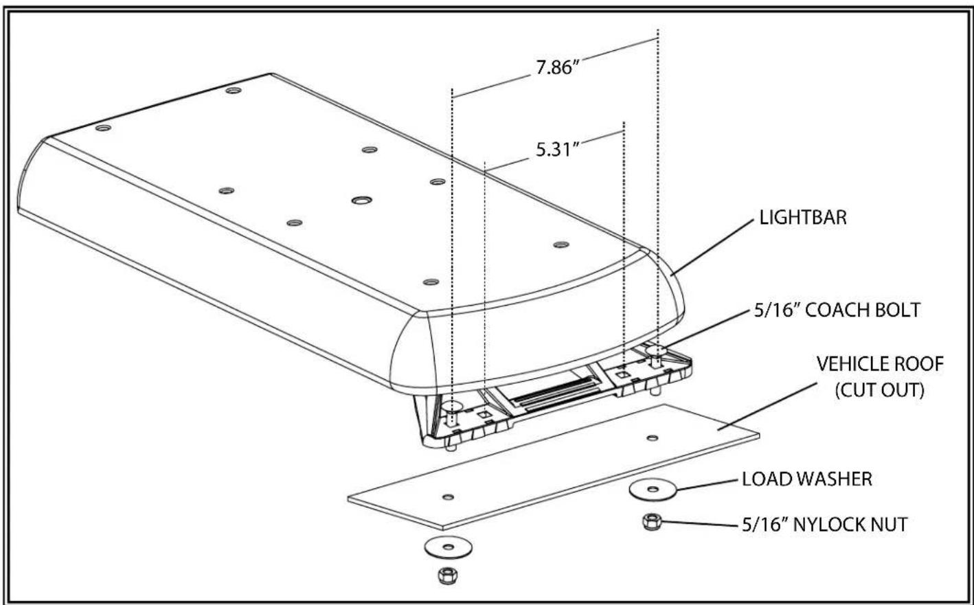
- Determine the position of the mounting feet and drill the 5/16"-11/32" diameter mounting holes accordingly, if needed. The spacing of the mounting feet from left to right is adjustable. It is suggested that the positioning of the feet be symmetrical and near the curved edges of the roof where the roof is strongest. Ideally, the outermost holes on the feet should be used for installation. The inner holes on the feet match the hole locations for 15 series lightbar and can be used when one of these lightbars has been previously installed.
- Mount the lightbar, with the bolts going through the holes drilled in step 2, routing the wire as planned in step 1 (refer to diagram). See the Wiring section of this manual for further wiring instructions. Install washers and nuts and secure the unit.
Gutter Mounting
Important!
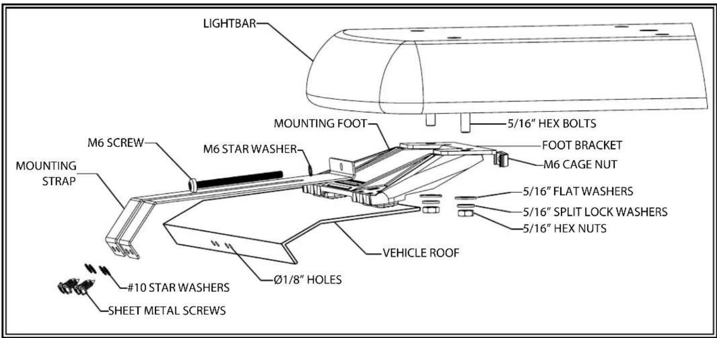
Mounting brackets are specific to the vehicle model. Please make sure the brackets are suitable for the vehicle before installation.
- Remove mounting foot. Position bracket onto nubs of the foot.
- Holding the bracket and foot together, insert the cage nut as shown. It will fit snugly underneath the mounting foot. Do not install it on the outside face.
- Install the mounting feet in reverse order of their removal. The metal bracket will be sandwiched between the bar and the composite mounting foot. Adjust the spacing of the mounting feet before securely tightening the nuts.
- Hand thread the M6 bolt through the star washer and mounting strap into the cage nut. Be careful not to cross thread the bolt, and leave loose until later steps.
- Once the bar is in position, use the strap as a template to drill ∅1/8" holes. It may be necessary to pull back the door sealing gasket or trim. Apply silicone or sealant around the hole, behind the strap. Secure the straps with the provided #10 stainless steel sheet metal screws with washers as shown. Screws should be tightened around 5-10 in-lb.
- Tighten the M6 bolts evenly so that the bar is even and centered. Reinstall any removed trim and/or weather-stripping and close doors to check secure fit of the lightbar.
12+ Series Roof Mounting Kits
(Please call Customer Service for more options)
Vehicle
P/N
FORD,TRUCK,SUPERDUTY,'17 A1234RMK
FORD,TRUCK,F150,'15-'17 A1234RMK
DODGE,TRUCK,1500,'09-'17 A1236RMK
CHEVY/GM,TRUCK,1500,2500,3500,'14-'17 A1237RMK
GM,TAHOE/YUKON,'14-'17 A1237RMK
TOYOTA,TACOMA,'05-'17 A1238RMK
TOYOTA, TUNDRA, '15-'17 A1239RMK
HEADACHE RACK MOUNTING BRACKETS A1032RMK
Wiring Instructions:
Important!
This unit is a safety device and it must be connected to its own separate, fused power point to assure its continued operation should any other electrical accessory fail. Do not wire in parallel with any other accessory.
Notes:
- Larger wires and tight connections will provide longer service life for components. For high current wires it is highly recommended that terminal blocks or soldered connections be used with shrink tubing to protect the connections. Do not use insulation displacement connectors (e.g., 3M Scotchlock type connectors).
- Route wiring using grommets and sealant when passing through compartment walls. Minimize the number of splices to reduce voltage drop. High ambient temperatures (e.g., under-hood) will significantly reduce the current carrying capacity of wires, fuses, and circuit breakers. All wiring should conform to the minimum wire size and other recommendations of the manufacturer and be protected from moving parts and hot surfaces. Looms, grommets, cable ties, and similar installation hardware should be used to anchor and protect all wiring.
- Fuses or circuit breakers should be located as close to the power takeoff points as possible and properly sized to protect the wiring and devices.
- Particular attention should be paid to the location and method of making electrical connections and splices to protect these points from corrosion and loss of conductivity.
- Ground termination should only be made to substantial chassis components, preferably directly to the vehicle battery.
- Circuit breakers are very sensitive to high temperatures and will "false trip" when mounted in hot environments or operated close to their capacity.

CAUTION!
Disconnect the battery before wiring up the lightbar, to prevent accidental shorting, arcing and/or electrical shock.
General Wiring Instructions
Before attempting to connect the lightbar wiring harness, refer to the wiring diagram illustrated below. The wiring diagram describes the function for each separate wire.
- Route the lightbar power cable's red wire to a fused, ignition-switched power point. Connect the black wire to a solid ground connection on the vehicle (ideally, directly to the battery negative terminal). Use a fuse according to the wiring diagram.
- After the lightbar has been mounted, route the control cable into the vehicle to the switch panel/controller location.
- Connect the wires of the lightbar wiring harness to the switched side of each switch, or plug into optional controller. See the wiring diagram for wire color/function legend.
- Use cable ties and grommets to secure and protect all cables and wires.
Wiring Diagram

flowchart
graph TD
    A["Ignition Switch"] --> B["20A"]
    B --> C["BLK"]
    C --> D["Power Cable Control Cable"]
    D --> E["12+ SERIES LIGHTBAR"]
    E --> F["4 Pin Adapter (optional)"]
    F --> G["Junction Box"]
    G --> H["Optional Wire Control"]
    H --> I["Batt +"]
    H --> J["Safety Director Harness"]
    J --> K["(Yellow) Right Build"]
    J --> L["(Green) Wlg Wag"]
    J --> M["(Black) Left Build"]
    J --> N["(Blue) Center Out"]
    J --> O["(White) Sync"]
    J --> P["(Brown) Aux Out"]
    Q["Batt+"] --> R["Pattern 1 (Brown)"]
    Q --> S["Pattern 2 (Orange)"]
    Q --> T["Alley Left (Yellow)"]
    Q --> U["Alley Right (Green)"]
    Q --> V["Worklight/Takedown (Blue)"]
    Q --> W["Pattern Sel (Violet)"]
    X["9-Pin Adapter (Supplied)"] --> Y["OR"]
    Z["Basic Control Pad (Optional)"] --> AA["Only used on the 3-wire systems. For 2-wire systems, cap the red wire"]
    AB["Advanced Control Pad"] --> AC["Only used on the 3-wire systems. For 2-wire systems, cap the red wire"]
    AD["Ignition Switch"] --> AE["1~2A"]
    AF["BLK"] --> AG["Red"]
    AH["Yellow"] --> AI["For passenger side cable exit, Yellow is right turn/stop and Green is left turn/stop and"]
    AI --> AJ["Only used on the 3-wire systems. For 2-wire systems, cap the red wire"]
Options and Maintenance:
Occasional cleaning of the lenses will ensure optimum light output. Take care when cleaning lenses – although tough, polycarbonate scratches easily. Clean the lens and base with soap and water or a lens polish using a soft cloth. Do not use solvents as they may damage the polycarbonate. Do not subject the lightbar to high-pressure washers or automatic car washers.
Lens Removal and Installation
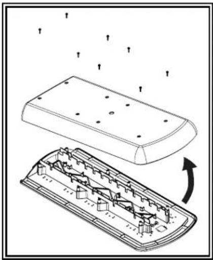
- Remove the screws from the lenses. Starting at one edge, pull the lens off.
- Carefully lift the lens off the seal – choose a suitable location to temporarily store the lens so as to not scratch the surface.
- When reinstalling, gently apply pressure around the lens taking care not to damage the seal. Replace the screws.
natural_image
Technical illustration of a device with internal components and airflow indicators (no text or symbols)Warning LED Modules (EZ1201X, EZ1203X, EZ1206XX)
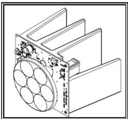
The LED lightheads have been designed to ensure long service life using high performance LEDs. The modules are low profile units that have a high intensity output with low current draw. The LED lightheads can be mounted in the front, rear and corners of the lightbar.


natural_image
Technical line drawing of a three-segment electrical enclosure (no text or symbols)Alley / Takedown / Worklight LED Modules (EZ0003)
Alley / Takedown / Worklight LED Module can be mounted anywhere in the lightbar.
natural_image
Technical line drawing of a mechanical assembly with circular components and mounting brackets (no text or symbols)Stop / Tail / Turn LED Modules (EZ1205)
Stop Tail Turn modules operate in conjunction with the vehicle tail, brake and direction indicator lights. Kit includes a pair of modules, control circuit and cable.
natural_image
Technical line drawing of a mechanical assembly with three cylindrical components and connecting rods (no text or symbols)
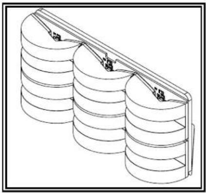
Basic Control Pad (EZ0006)
The EZ0006 optional in-cab controller provides convenient control of the lightbar's built-in flash patterns and features soft touch buttons and LED function indicator lights.
Operation
The 12+ series basic control pad consists of 7 buttons with 5 features, and 6 indicator windows. When a feature button is selected, the corresponding clear indicator(s) will illuminate. Pressing any of the 5 feature buttons will turn that corresponding feature on, pressing it again will turn it off. There are two large flash pattern preset buttons; only one can be selected at a time. If one is on while the other is selected, it will shut the previous one off. The "OFF and "SEL" buttons do not have illuminated indicators.

"OFF" - Turns the whole bar off. This is a quick way to shut everything down. Features can also be shut down individually by pushing the feature's button.


"Power 1, Power 2" - Turns on the flash pattern presets.

"AL" - Turns on left alley light, or as custom configured.
"WL" - Turns on center pair of takedown and/or worklights, or as custom configured.
"AR" - Turns on right alley light, or as custom configured.

"SEL"-Double press to enter flash pattern select mode and cycle to the next flash pattern. Press again to cycle to the next flash pattern. Press and hold for 3 seconds to return to the prior flash pattern. The lightbar will store the last flash pattern used to the active preset.
natural_image
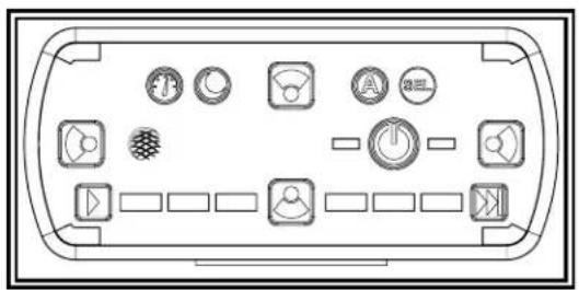
Top-down schematic of a device control panel with various function buttons and icons (no text labels)Advanced Control Pad (EZ1202)
The EZ1202 optional in-cab advanced control pad provides convenient control of the lightbar's built-in flash patterns and features soft touch buttons and LED function indicator lights.
Operation
The 12+ series advanced control pad consists of 11 buttons.

"Power" - Press to cycle through three programmable flash pattern presets. Hold button down to shut down all functions. Press again to resume as before.


"Cruise" - Press to illuminate all directional modules in steady burn mode.

"Day/Night Mode" - Press to backlight the keypad and lower the brightness of the directional modules in the lightbar.

"Auxiliary Output" - For use with the auxiliary output from the junction box to a relay (customer supplied), to control any auxiliary device via the junction box controlled relay.

"Flash Pattern Select" - Double press to enter flash pattern select mode and cycle one flash pattern. The 4 corner LEDs on the controller will mimic the lightbar to give pattern feedback. Press again once to cycle to the next flash pattern. Press and hold for 3 seconds to return to the prior flash pattern. The lightbar will store the last flash pattern used to the active preset.
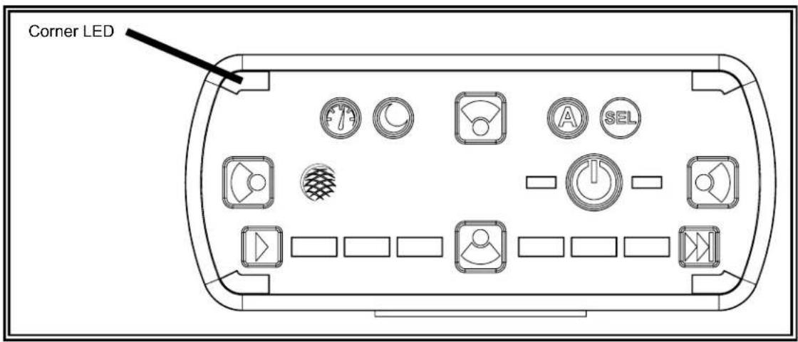
"Safety Director On/Off" - Will resume pattern selected.
"Safety Director Pattern Select" - Press once to cycle to the next Safety Director flash pattern. There is a 5 second delay between the controller and the lightbar. Press and hold for 3 seconds to return to the prior flash pattern. The lightbar will store the last flash pattern used.

"Forward Worklamp" - Will turn on forward facing worklamps.

"Rear Worklamp" - Will turn on rear facing worklamps.

"Alley Left" - Will turn on the left alley light.

"Alley Right" - Will turn on the right alley light.
Special Features:
Touchpad Backlight

Press and hold the "Day/Night" button to turn on the touchpad backlight
Safety Director Module Selection


To change the number of modules used in the safety director, press and hold ▶ - tap ▶ to select 6 to 10 modules.

Safety Director Front/Rear Selection

Press ▶ to turn on the safety director.
Press and hold ▶, once the corner LEDs light, tap ▶ to cycle front, rear or both.
Basic Control Pad Mounting:
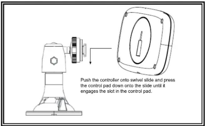
To mount the control pad with Velcro, separate the two circular halves, remove the backing and adhere one piece on the vehicle dashboard and adhere the other to the back of the control pad. To mount the control pad using the swivel mount, first mount the swivel unit to the dashboard with either the supplied screws (note, the suction cup will not work after drilling screws through the swivel base) or by turning the lever at the base of the swivel unit to engage the suction cup. Push the control pad onto the swivel slide and press the control pad down onto the slide until it engages the slot in the control pad. (You may need to turn the control pad clockwise once engaged with the slide to tighten it.) Turn the dial on the swivel head to tighten it against the back of the control pad. Finally, loosen the hand screw on the swivel neck to adjust the angle of the control pad. Hold the pad in the desired position while tightening the hand screw on the swivel neck.
Advanced Control Pad Mounting:
The advanced control pad is supplied with three mounting options: a bracket, VHB tape and hook and loop patch. The rear of the control pad is designed to allow for the cable exit to be routed five different ways to maximize installation locations. Mount the control pad in a location within convenient reach of the operator so that s/he can operate the system without losing eye contact with the roadway.

Replacement Parts/Accessories:
| Description Part No. | |
| Lenses | |
| REPLACEMENT END LENS ER0003 | |
| REPLACEMENT MID LENS ER0004 | |
| LEDs | |
| ACC,MODULE,LED,12+ SER,AMBER EZ1203A | |
| ACC,MODULE,LED,12+ SER,BLUE EZ1203B | |
| ACC,MODULE,LED,12+ SER,RED EZ1203R | |
| ACC,MODULE,LED,12+ SER,GREEN EZ1203G | |
| ACC,MODULE,LED,12+ SER,WHITE EZ1203W | |
| ACC,MODULE,LED,12+ SER,AMBER/BLUE EZ1206AB | |
| ACC,MODULE,LED,12+ SER,AMBER/WHITE EZ1206AW | |
| ACC,MODULE,LED,12+ SER,AMBER/RED EZ1206AR | |
| ACC,MODULE,LED,12+ SER,BLUE/WHITE EZ1206BW | |
| ACC,MODULE,LED,12+ SER,RED/WHITE EZ1206RW | |
| ACC,MODULE,LED,12+ SER,RED/BLUE EZ1206RB | |
| ACC,MODULE,LED,12+ SER,FLARE, AMBER EZ1201A | |
| ACC,MODULE,LED,12+ SER,FLARE,BLUE EZ1201B | |
| ACC,MODULE,LED,12+ SER,FLARE, RED EZ1201R | |
| ACC,MODULE,LED,12+ SER,FLARE, GREEN | EZ1201G |
| ACC,MODULE,LED,12+ SER,FLARE, WHITE | EZ1201W |
| LED,ALLEYWORKLIGHT,12+ SERIES | EZ1204 |
| LED,STI,12+ SERIES | EZ1202AR |
| LED,STT,12+ SERIES | EZ1205 |
| Cables | |
| ACCESSORY,CABLE,CONTROL, 15' EZ0008 | |
| CONTROLLER CABLE - 8' | EZ1413 |
| CONTROLLER CABLE - 48' | EZ1413-48 |
| Touch Pad | |
| CONTROLLER,TOUCHPAD,12+ SERIES | EZ1202 |
| ACCESSORY IN-CAB CONTROLLER EZ0006 | |
| JBOX | |
| J-BOX,12+SERIES,DISCRETE WIRE CONTROL | EZ1207 |
| Mounting | |
| REPLACEMENT,FOOT,PAIR | ER0002 |
| ACCESSORY,RACK MOUNT KIT,10 15 20 30 SER | A1032RMK |
Troubleshooting:
All lightbars are thoroughly tested prior to shipment. However, should you encounter a problem during installation or during the life of the product, follow the guide below for troubleshooting and repair information. If the problem cannot be rectified using the solutions given below, additional information may be obtained from the manufacturer – contact details are at the end of this document.
LIGHTBAR AND CONTROLLER
| PROBLEM POSSIBLE CAUSE SOLUTION | ||
| Does not function | Poor power or ground connection | If controller functions normally, or if a 12/24V control voltage is present on either the Pattern 1 (brown) or Pattern 2 (orange) wires, then replace the driver board in the lightbar.If controller does not function, then check fuse, cables, and connections to the lightbar and to the controller. |
| Blown fuse Check wiring, replace fuse | ||
| One or two LED head do not flash, but Pattern 1 or Pattern 2 indicator LED on control module is on. | Open circuit wiring from control module to LED head | Connect a known-good LED head to the problem output to ensure the control module is working correctly. Repair or replace. |
| Failed LED head Replace LED head | ||
| LED head flashes dimly Defective head | d or driver board Check correct LED head | |
| Incorrect flash patterns | Wrong flash configuration | Re-program the lightbar flash pattern for either Program 1 or Program 2, or both. |
| Secondary pattern does not function | Normal operation Primary function overrides secondary function – turn off primary function | |
| PROBLEM POSSIBLE CAUSE SOLUTION | ||
| Light does not function | Defective light Replace light | |
| Defective controller | If indicator LED on controller is lit, then it is either the light, or the cable to the light, or the driver board. Otherwise the controller is defective. | |
STOP/TAIL/TURN
| PROBLEM POSSIBLE CAUSE SOLUTION | ||
| Both/all lights do not function | Blown fuse Check wiring, replace fuse | |
| No power Check to see if vehicle S/T/T lights function properly | ||
| Failed S/T/T LED head | Make sure that the S/T/T head is plugged into the S/T/T control board and not the driver board. Replace S/T/T LED head and/or its cable. | |

NOTE: Operating the vehicle without the outer lens installed on the product may result in damage that will NOT be used under the warranty.
Manufacturer Limited Warranty and Limitation of Liability:
Manufacturer warrants that on the date of purchase, this product will conform to Manufacturer's specifications for this product (which are available from the Manufacturer upon request). This Limited Warranty extends for Sixty (60) months from the date of purchase.
DAMAGE TO PARTS OR PRODUCTS RESULTING FROM TAMPERING, ACCIDENT, ABUSE, MISUSE, NEGLIGENCE, UNAPPROVED MODIFICATIONS, FIRE OR OTHER HAZARD; IMPROPER INSTALLATION OR OPERATION; OR NOT BEING MAINTAINED IN ACCORDANCE WITH THE MAINTENANCE PROCEDURES SET FORTH IN MANUFACTURER'S INSTALLATION AND OPERATING INSTRUCTIONS VOIDS THIS LIMITED WARRANTY.
Exclusion of Other Warranties:
MANUFACTURER MAKES NO OTHER WARRANTIES, EXPRESSED OR IMPLIED. THE IMPLIED WARRANTIES FOR MERCHANTABILITY, QUALITY OR FITNESS FOR A PARTICULAR PURPOSE, OR ARISING FROM A COURSE OF DEALING, USAGE OR TRADE PRACTICE ARE HEREBY EXCLUDED AND SHALL NOT APPLY TO THE PRODUCT AND ARE HEREBY DISCLAIMED, EXCEPT TO THE EXTENT PROHIBITED BY APPLICABLE LAW. ORAL STATEMENTS OR REPRESENTATIONS ABOUT THE PRODUCT DO NOT CONSTITUTE WARRANTIES.
Remedies and Limitation of Liability:
MANUFACTURER'S SOLE LIABILITY AND BUYER'S EXCLUSIVE REMEDY IN CONTRACT, TORT (INCLUDING NEG-LIGENCE), OR UNDER ANY OTHER THEORY AGAINST MANUFACTURER REGARDING THE PRODUCT AND ITS USE SHALL BE, AT MANUFACTURER'S DISCRETION, THE REPLACEMENT OR REPAIR OF THE PRODUCT, OR THE REFUND OF THE PURCHASE PRICE PAID BY BUYER FOR NON-CONFORMING PRODUCT. IN NO EVENT SHALL MANUFACTURER'S LIABILITY ARISING OUT OF THIS LIMITED WARRANTY OR ANY OTHER CLAIM RELATED TO THE MANUFACTURER'S PRODUCTS EXCEED THE AMOUNT PAID FOR THE PRODUCT BY BUYER AT THE TIME OF THE ORIGINAL PURCHASE. IN NO EVENT SHALL MANUFACTURER BE LIABLE FOR LOST PROFITS, THE COST OF SUBSTITUTE EQUIPMENT OR LABOR, PROPERTY DAMAGE, OR OTHER SPECIAL, CONSEQUENTIAL, OR INCIDENTAL DAMAGES BASED UPON ANY CLAIM FOR BREACH OF CONTRACT, IMPROPER INSTALLATION, NEGLIGENCE, OR OTHER CLAIM, EVEN IF MANUFACTURER OR A MANUFACTURER'S REPRESENTATIVE HAS BEEN ADVISED OF THE POSSIBILITY OF SUCH DAMAGES. MANUFACTURER SHALL HAVE NO FURTHER OBLIGATION OR LIABILITY WITH RESPECT TO THE PRODUCT OR ITS SALE, OPERATION AND USE, AND MANUFACTURER NEITHER ASSUMES NOR AUTHORIZES THE ASSUMPTION OF ANY OTHER OBLIGATION OR LIABILITY IN CONNECTION WITH SUCH PRODUCT.
This Limited Warranty defines specific legal rights. You may have other legal rights which vary from jurisdiction to jurisdiction. Some jurisdictions do not allow the exclusion or limitation of incidental or consequential damages.

EPCOM Industrial®
www.syscom.mx
- Installation and Operation Instructions 12+ Series Vantage™ Lightbars
- Introduction:
- Unpacking and Pre-Installation:
- Do not install and/or operate this safety product unless you have read and understand the safety information contained in this manual.
- WARNING!
- Specifications:
- Installation & Mounting:
- Mounting
- Caution:
- Permanent Mounting
- Gutter Mounting
- Important!
- 12+ Series Roof Mounting Kits
- Wiring Instructions:
- Notes:
- CAUTION!
- General Wiring Instructions
- Options and Maintenance:
- Lens Removal and Installation
- Warning LED Modules (EZ1201X, EZ1203X, EZ1206XX)
- Alley / Takedown / Worklight LED Modules (EZ0003)
- Stop / Tail / Turn LED Modules (EZ1205)
- Basic Control Pad (EZ0006)
- Operation
- Advanced Control Pad (EZ1202)
- Special Features:
- Safety Director Module Selection
- Safety Director Front/Rear Selection
- Basic Control Pad Mounting:
- Advanced Control Pad Mounting:
- Troubleshooting:
Brand : Epcom
Model : VTG48A
Category : Beacon light