
CBLR2-USB - Electronic accessory Crestron - Free user manual and instructions
Find the device manual for free CBLR2-USB Crestron in PDF.


| Product Type | USB Cable/Adapter |
| Brand | Crestron |
| Model | CBLR2-USB |
| Connector Type | USB-A to USB-C |
| Cable Length | 1.8 m (6 ft) |
| Data Transfer Rate | Up to 5 Gbps (USB 3.0) |
| Compatibility | USB-C and Thunderbolt 3 devices |
| Power Delivery | Up to 60W (20V/3A) |
| Shielding | Triple shielding for signal integrity |
| Dimensions (cable only) | 1.8 m length, 5 mm diameter |
| Weight | Approx. 50 g |
| Color | Black |
| Usage | Connect USB-C peripherals to USB-A host |
| Features | Backward compatible with USB 2.0 |
| Warranty | 1 year limited |
| Certifications | CE, FCC, RoHS |
| Operating Temperature | 0°C to 40°C |
| Storage Temperature | -20°C to 60°C |
| Cleaning | Wipe with a dry cloth; do not use liquids |
| Safety | Keep away from water and heat sources |
Frequently Asked Questions - CBLR2-USB Crestron
User questions about CBLR2-USB Crestron
0 question about this device. Answer the ones you know or ask your own.
Ask a new question about this device
Download the instructions for your Electronic accessory in PDF format for free! Find your manual CBLR2-USB - Crestron and take your electronic device back in hand. On this page are published all the documents necessary for the use of your device. CBLR2-USB by Crestron.
USER MANUAL CBLR2-USB Crestron
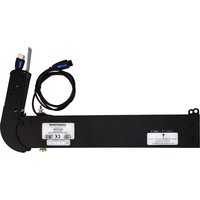
Cable Retractors for FlipTops ^™
DO Prepare the FlipTop
Preparation of the Crestron® FlipTop™ consists of the following:
- Modifying the RipTop assembly to accommodate the cable retractors
- Determining the desired mounting orientation (Retractors are shipped configured for vertical
orientation, but are easily reconfigured for horizontal orientation.)
NOTE: The CBLR2-DP-V and CBLR2-DP-H models are dedicated to vertical and horizontal orientation, respectively.
NOTE: For preparation of the FipTop 600 Series models, refer to "Modify the FipTop (FipTop 600 Series Models)."
Modify the FlipTop (Excludes FlipTop 600 Series Models)
-
Remove four screws (A) to attach the lower bar assembly. Also remove two screws (H). Retain screws A and B to attach the FlipTop mounting bracket assembly. Refer to the FlipTop mounting brackets table provided in the "DO Check the Accessories" section on the next page to ensure that the mounting bracket received is appropriate for the FlipTop being modified.
-
Remove four screws (C) to detach the cable guide. Retain the screws to attach the two side tiller plates (sold separately).
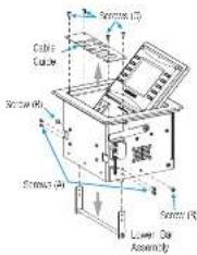
- Move the mounting bracket assembly up into position and secure it using four screws (A) and two screws (B) removed in step 1.

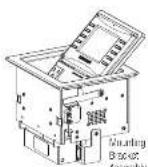

- Post on the side filler plates and secure them using four screws (C).

Modify the FlipTop (FlipTop 600 Series Models)
Retractors can be installed in both the left and right sides of the FlipTop 600 Series models.
-
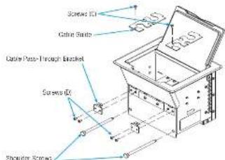
Remove the screw (C) holding the cable guide in place, and then remove the cable guide.
-
Remove the screws (D) holding the cable pass-through bracket in place, and then remove the cable pass-through bracket.
-
Remove the shoulder screws from the front of the unit. Save these as they are used in retractor installation.
Reconfigure the Retractors for Horizontal Operation
NOTE: The C8L R2-DP-V and C8L R2-DP-H models are dedicated to vertical and horizontal orientation, respectively.
To reconfigure the retractors for horizontal orientation, refer to the following illustrations and perform these steps:
- Remove the four screws (E), two from each side of the retractor, that attach the neck in the vertical orientation.

- Reposition the neck as shown in the horizontal orientation view and attach it using the four screws (E) to secure the neck in that position.

DO Adjust the Retractor
Once the retractor arm configuration is set, refer to the following illustration and adjust the retractor arm tension and cable retraction speed as follows:
-
Adjust the retractor tension by loosening the top thumb screw enough to enable pulling or pushing of the adjacent cable end. Align the red screw with the label arrow.
-
Adjust the cable refraction speed.
a. Pull the knob outward and move it to the VERT or HORIZ position to match the configuration of the retractor arms.
b. Pull the cable (plug and) out so it is fully extended.
c. Pull the cable a second time to cause it to retract, and observe the speed of the cable retraction. If it is too slow or too fast, reposition the knob to an intermediate position and racheck.

DO Attach the Retractors
The final assembly consists of attaching the cable retractors to the FlipTop box.
During the following procedures, refer to the accompanying illustrations.
Attach the Cable Retractors to the FlipTop (Excludes FlipTop 600 Series Models)
- Insert the necks of the retractors and any included spacers up and into the mounting bracket assembly until they engage the frame of the assembly.
- Carefully slide the clevis pin through the hole in the side of the mounting bracket assembly and then through each item being mounted until it protrudes through the opposite side of the assembly.
- Insert the supplied hairpin cutter pin into the hole in the clevis pin.
- Tighten the screws in the neck assemblies so they are just snug against the clevis pin.

Attach the Cable Retractors to the FlipTop (FlipTop 600 Series Models)
- Insert the necks of the retractors into the FloTop until they engage the frame of the assembly.
- Insert the shoulder screws into the front of the FlipTop.
- Tighten each individual set screw on the retractors.

DO Check the Accessories
NOTE: The following excludes FlipTop 600 Series models.
| DOMESTIC MODELS | INTERNATIONAL MODELS | ||
| (3-Position) (2-Position) (1-Position) | |||
| Mounting Bracket Assemblies | CBL/IA-B/RT-3-FT606101 | CBL/IA-B/RT-4-FT8306192 | CBL/IA-B/RT-4-FT8306188 |
| Applicable FlipTop Models | FT-PWR-D C2N-FTR-TPS4 FT-PWR-D | ||
| QM-FTCC C2N-FTR-TPS4-U QM-FTCC | |||
| QM-FTCC-NB FT-PWR-D-LG QMI-FTCSC | |||
| QM-FTDC GM-FTCC-TPS4 QMI-FTDC | |||
| QM-FTDC-NB | QMI-FTMC | ||
| QM-FTMC | |||
There are two spacer insert models, which can be used to fill unpopulated intractor slots:
• CHLRA INSERT BLANK, Part No. 650E163
• CBLRA-INSERT-2WIRE, Part No. 6506184
DO Learn More
Crestron Electronios 15 Volvo Drive, Rackleigh, NJ 07647
888.CRESTRON | www.crestiron.com

CE As of the calls of manufacturers, the CBLH2 Series has been tested and found to comply with specifications for GL marking
The cost of the stock is a free cash flow, which is not available for any portion of the company. The company has a net cash flow of \$100,000.

CRESTRON

GUIDE
DOC.7711A(2002317)10.14

- DO Prepare the FlipTop
- Modify the FlipTop (Excludes FlipTop 600 Series Models)
- Modify the FlipTop (FlipTop 600 Series Models)
- Reconfigure the Retractors for Horizontal Operation
- DO Adjust the Retractor
- DO Attach the Retractors
- Attach the Cable Retractors to the FlipTop (Excludes FlipTop 600 Series Models)
- Attach the Cable Retractors to the FlipTop (FlipTop 600 Series Models)
- DO Check the Accessories
- DO Learn More
Brand : Crestron
Model : CBLR2-USB
Category : Electronic accessory