
Utility Cart - Utility cart LINCOLN ELECTRIC - Free user manual and instructions
Find the device manual for free Utility Cart LINCOLN ELECTRIC in PDF.


| Brand | Lincoln Electric |
| Model | Utility Cart |
| Product Type | Utility Cart |
| Primary Use | Transporting tools, equipment, and materials |
| Weight Capacity | Approximately 500 lbs (227 kg) |
| Cart Material | Steel with powder-coated finish |
| Handle Type | Pull handle with ergonomic grip |
| Wheel Configuration | Two fixed rear wheels, two swivel front wheels |
| Wheel Diameter | 8 inches (20.3 cm) |
| Overall Dimensions (L x W x H) | 42 x 24 x 36 inches (107 x 61 x 91 cm) |
| Deck Size | 36 x 20 inches (91 x 51 cm) |
| Weight | Approximately 85 lbs (38.6 kg) |
| Power Source | Manual (no electrical power required) |
| Assembly Required | Yes, partial assembly required (wheels and handle) |
| Included Tools | Wrench and pins for assembly |
| Maintenance | Periodic lubrication of wheels and tightening of bolts |
| Cleaning | Wipe with damp cloth; avoid abrasive cleaners |
| Safety Feature | Locking swivel wheels for stability |
| Spare Parts Availability | Wheels, handle grips, and hardware available from Lincoln Electric |
| Repairability | Modular design; most parts can be replaced individually |
| Warranty | 1-year limited warranty |
| Country of Origin | USA |
| Certifications | None specific to utility cart |
| Manual Languages | English (other languages available upon request) |
Frequently Asked Questions - Utility Cart LINCOLN ELECTRIC
User questions about Utility Cart LINCOLN ELECTRIC
0 question about this device. Answer the ones you know or ask your own.
Ask a new question about this device
Download the instructions for your Utility cart in PDF format for free! Find your manual Utility Cart - LINCOLN ELECTRIC and take your electronic device back in hand. On this page are published all the documents necessary for the use of your device. Utility Cart by LINCOLN ELECTRIC.
USER MANUAL Utility Cart LINCOLN ELECTRIC
natural_image
Black industrial cart with wheels and handle, no visible text or symbolsFor use with machines having Code Numbers:
K520, K520-1

Register your machine:
www.lincolnelectric.com/register
Authorized Service and Distributor Locator:
www.lincolnelectric.com/locator
Save for future reference
Date Purchased
Code: (ex: 10859)
Serial: (ex: U1060512345)
Need Help? Call 1.888.935.3877
to talk to a Service Representative
Hours of Operation:
8:00 AM to 6:00 PM (ET) Mon. thru Fri.
After hours?
Use "Ask the Experts" at lincolnelectric.com
A Lincoln Service Representative will contact you no later than the following business day.
For Service outside the USA:
Email: globalservice@lincolnelectric.com
THANK YOU FOR SELECTING A QUALITY PRODUCT BY LINCOLNELECTRIC.
PLEASE EXAMINE CARTON AND EQUIPMENT FOR DAMAGE IMMEDIATELY
When this equipment is shipped, title passes to the purchaser upon receipt by the carrier. Consequently, claims for material damaged in shipment must be made by the purchaser against the transportation company at the time the shipment is received.
SAFETY DEPENDS ON YOU
Lincoln arc welding and cutting equipment is designed and built with safety in mind. However, your overall safety can be increased by proper installation ... and thoughtful operation on your part. DO NOT INSTALL, OPERATE OR REPAIR THIS EQUIPMENT WITHOUT READING THIS MANUAL AND THE SAFETY PRECAUTIONS CONTAINED THROUGHOUT. And, most importantly, think before you act and be careful.

WARNING
This statement appears where the information must be followed exactly to avoid serious personal injury or loss of life.

CAUTION
This statement appears where the information must be followed to avoid minor personal injury or damage to this equipment.
KEEP YOUR HEAD OUT OF THE FUMES.
DON'T get too close to the arc. Use corrective lenses if necessary to stay a reasonable distance away from the arc.
READ and obey the Safety Data Sheet (SDS) and the warning label that appears on all containers of welding materials.
USE ENOUGH VENTILATION or exhaust at the arc, or both, to keep the fumes and gases from your breathing zone and the general area.

natural_image
Illustration of a person in protective gear using a welding torch to prevent impact (no text or symbols)IN A LARGE ROOM OR OUTDOORS, natural ventilation may be adequate if you keep your head out of the fumes (See below).
USE NATURAL DRAFTS or fans to keep the fumes away from your face.
If you de velop unusual symptoms, see your supervisor.
Perhaps the welding atmosphere and ventilation system should be checked.

natural_image
Silhouette of a person wearing a welding helmet and holding a tool, no text or symbols presentWEAR CORRECT EYE, EAR & BODY PROTECTION
PROTECT your eyes and face with welding helmet properly fitted and with proper grade of filter plate (See ANSI Z49.1).
PROTECT your body from welding spatter and arc flash with protective clothing including woolen clothing, flame-proof apron and gloves, leather leggings, and high boots.
PROTECT others from splatter, flash, and glare with protective screens or barriers.
IN SOME AREAS, protection from noise may be appropriate.
BE SURE protective equipment is in good condition.
Also, wear safety glasses in work area AT ALL TIMES.

SPECIAL SITUATIONS
DO NOT WELD OR CUT containers or materials which previously had been in contact with hazardous substances unless they are properly cleaned. This is extremely dangerous.
DO NOT WELD OR CUT painted or plated parts unless special precautions with ventilation have been taken. They can release highly toxic fumes or gases.
Additional precautionary measures
PROTECT compressed gas cylinders from excessive heat, mechanical shocks, and arcs; fasten cylinders so they cannot fall.
BE SURE cylinders are never grounded or part of an electrical circuit.
REMOVE all potential fire hazards from welding area.
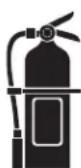
ALWAYS HAVE FIRE FIGHTING EQUIPMENT READY FOR IMMEDIATE USE AND KNOW HOW TO USE IT.

SECTION A: WARNINGS

CALIFORNIA PROPOSITION 65 WARNINGS

WARNING: Breathing diesel engine exhaust exposes you to chemicals known to the State of California to cause cancer and birth defects, or other reproductive harm.
• Always start and operate the engine in a well-ventilated area.
- If in an exposed area, vent the exhaust to the outside.
- Do not modify or tamper with the exhaust system.
- Do not idle the engine except as necessary.
For more information go to www.P65 warnings.ca.gov/diesel
WARNING: This product, when used for welding or cutting, produces fumes or gases which contain chemicals known to the State of California to cause birth defects and, in some cases, cancer. (California Health & Safety Code § 25249.5 et seq.)

WARNING: Cancer and Reproductive Harm www.P65warnings.ca.gov
ARC WELDING CAN BE HAZARDOUS. PROTECT YOURSELF AND OTHERS FROM POSSIBLE SERIOUS INJURY OR DEATH. KEEP CHILDREN AWAY. PACEMAKER WEARERS SHOULD CONSULT WITH THEIR DOCTOR BEFORE OPERATING.
Read and understand the following safety highlights. For additional safety information, it is strongly recommended that you purchase a copy of "Safety in Welding & Cutting - ANSI Standard Z49.1" from the American Welding Society, P.O. Box 351040, Miami, Florida 33135 or CSA Standard W117.2. A Free copy of "Arc Welding Safety" booklet E205 is available from the Lincoln Electric Company, 22801 St. Clair Avenue, Cleveland, Ohio 44117-1199.
BE SURE THAT ALL INSTALLATION, OPERATION, MAINTENANCE AND REPAIR PROCEDURES ARE PERFORMED ONLY BY QUALIFIED INDIVIDUALS.

FOR ENGINE POWERED EQUIPMENT.
1.a. Turn the engine off before troubleshooting and maintenance work unless the maintenance work requires it to be running.

1.b. Operate engines in open, well-ventilated areas or vent the engine exhaust fumes outdoors.
1.c. Do not add the fuel near an open flame welding arc or when the engine is running. Stop the engine and allow it to cool before refueling to prevent spilled fuel from vaporizing on contact

with hot engine parts and igniting. Do not spill fuel when filling tank. If fuel is spilled, wipe it up and do not start engine until fumes have been eliminated.
1.d. Keep all equipment safety guards, covers and devices in position and in good repair. Keep hands, hair, clothing and tools away from V-belts, gears, fans and all other moving parts when starting, operating or repairing equipment.

1.e. In some cases it may be necessary to remove safety guards to perform required maintenance. Remove guards only when necessary and replace them when the maintenance requiring their removal is complete. Always use the greatest care when working near moving parts.
1.f. Do not put your hands near the engine fan. Do not attempt to override the governor or idler by pushing on the throttle control rods while the engine is running.
1.g. To prevent accidentally starting gasoline engines while turning the engine or welding generator during maintenance work, disconnect the spark plug wires, distributor cap or magneto wire as appropriate.
1.h. To avoid scalding, do not remove the radiator pressure cap when the engine is hot.
1.i. Using a generator indoors CAN KILL YOU IN MINUTES.
1.j. Generator exhaust contains carbon monoxide. This is a poison you cannot see or smell.
1.k. NEVER use inside a home or garage, EVEN IF doors and windows are open.
- I. Only use OUTSIDE and far away from windows, doors and vents.
1.m. Avoid other generator hazards. READ MANUAL BEFORE USE.


ELECTRIC AND MAGNETIC FIELDS MAY BE DANGEROUS

2.a. Electric current flowing through any conductor causes localized Electric and Magnetic Fields (EMF). Welding current creates EMF fields around welding cables and welding machines
2.b. EMF fields may interfere with some pacemakers, and welders having a pacemaker should consult their physician before welding.
2.c. Exposure to EMF fields in welding may have other health effects which are now not known.
2.d. All welders should use the following procedures in order to minimize exposure to EMF fields from the welding circuit:
2.d.1. Route the electrode and work cables together - Secure them with tape when possible.
2.d.2. Never coil the electrode lead around your body.
2.d.3. Do not place your body between the electrode and work cables. If the electrode cable is on your right side, the work cable should also be on your right side.
2.d.4. Connect the work cable to the workpiece as close as possible to the area being welded.
2.d.5. Do not work next to welding power source.
Safety 02 of 04 - 10/08/2021

ELECTRIC SHOCK CAN KILL.

3.a. The electrode and work (or ground) circuits are electrically "hot" when the welder is on. Do
not touch these "hot" parts with your bare skin or wet clothing. Wear dry, hole-free gloves to insulate hands.
3.b. Insulate yourself from work and ground using dry insulation. Make certain the insulation is large enough to cover your full area of physical contact with work and ground.
In addition to the normal safety precautions, if welding must be performed under electrically hazardous conditions (in damp locations or while wearing wet clothing; on metal structures such as floors, gratings or scaffolds; when in cramped positions such as sitting, kneeling or lying, if there is a high risk of unavoidable or accidental contact with the workpiece or ground) use the following equipment:
- Semiautomatic DC Constant Voltage (Wire) Welder.
• DC Manual (Stick) Welder.
• AC Welder with Reduced Voltage Control.
3.c. In semiautomatic or automatic wire welding, the electrode, electrode reel, welding head, nozzle or semiautomatic welding gun are also electrically "hot".
3.d. Always be sure the work cable makes a good electrical connection with the metal being welded. The connection should be as close as possible to the area being welded.
3.e. Ground the work or metal to be welded to a good electrical (earth) ground.
3.f. Maintain the electrode holder, work clamp, welding cable and welding machine in good, safe operating condition. Replace damaged insulation.
3.g. Never dip the electrode in water for cooling.
3.h. Never simultaneously touch electrically "hot" parts of electrode holders connected to two welders because voltage between the two can be the total of the open circuit voltage of both welders.
3.i. When working above floor level, use a safety belt to protect yourself from a fall should you get a shock.
3.j. Also see It ems 6.c. and 8.

ARC RAYS CAN BURN.
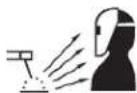
4.a. Use a shield with the proper filter and cover plates to protect your eyes from sparks and the rays of the arc when welding or observing open arc welding. Headshield and filter lens should conform to ANSI Z87. I standards.
4.b. Use suitable clothing made from durable flame-resistant material to protect your skin and that of your helpers from the arc rays.
4.c. Protect other nearby personnel with suitable, non-flammable screening and/or warn them not to watch the arc nor expose themselves to the arc rays or to hot spatter or metal.

5.a. Welding may produce fumes and gases hazardous to health. Avoid breathing these fumes and gases. When welding, keep your head out of the fume. Use enough ventilation and/or exhaust at the arc to keep fumes and gases away from the breathing zone. When welding hardfacing (see instructions on container or SDS) or on lead or cadmium plated steel and other metals or coatings which produce highly toxic fumes, keep exposure as low as possible and within applicable OSHA PEL and ACGIH TLV limits using local exhaust or mechanical ventilation unless exposure assessments indicate otherwise. In confined spaces or in some circumstances, outdoors, a respirator may also be required. Additional precautions are also required when welding on galvanized steel.
- b. The operation of welding fume control equipment is affected by various factors including proper use and positioning of the equipment, maintenance of the equipment and the specific welding procedure and application involved. Worker exposure level should be checked upon installation and periodically thereafter to be certain it is within applicable OSHA PEL and ACGIH TLV limits.
5.c. Do not weld in locations near chlorinated hydrocarbon vapors coming from degreasing, cleaning or spraying operations. The heat and rays of the arc can react with solvent vapors to form phosgene, a highly toxic gas, and other irritating products.
5.d. Shielding gases used for arc welding can displace air and cause injury or death. Always use enough ventilation, especially in confined areas, to insure breathing air is safe.
5.e. Read and understand the manufacturer's instructions for this equipment and the consumables to be used, including the Safety Data Sheet (SDS) and follow your employer's safety practices. SDS forms are available from your welding distributor or from the manufacturer.
5.f. Also see item 1.b.

WELDING AND CUTTING SPARKS CAN CAUSE FIRE OR EXPLOSION.
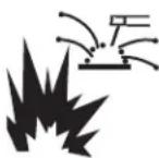
6.a. Remove fire hazards from the welding area. If this is not possible, cover them to prevent the welding sparks from starting a fire. Remember that welding sparks and hot materials from welding can easily go through small cracks and openings to adjacent areas. Avoid welding near hydraulic lines. Have a fire extinguisher readily available.
6.b. Where compressed gases are to be used at the job site, special precautions should be used to prevent hazardous situations. Refer to "Safety in Welding and Cutting" (ANSI Standard Z49.1) and the operating information for the equipment being used.
6.c. When not welding, make certain no part of the electrode circuit is touching the work or ground. Accidental contact can cause overheating and create a fire hazard.
6.d. Do not heat, cut or weld tanks, drums or containers until the proper steps have been taken to insure that such procedures will not cause flammable or toxic vapors from substances inside. They can cause an explosion even though they have been "cleaned". For information, purchase "Recommended Safe Practices for the Preparation for Welding and Cutting of Containers and Piping That Have Held Hazardous Substances", AWS F4.1 from the American Welding Society (see address above).
6.e. Vent hollow castings or containers before heating, cutting or welding. They may explode.
6.f. Sparks and spatter are thrown from the welding arc. Wear oil free protective garments such as leather gloves, heavy shirt, cuffless trousers, high shoes and a cap over your hair. Wear ear plugs when welding out of position or in confined places. Always wear safety glasses with side shields when in a welding area.
6.g. Connect the work cable to the work as close to the welding area as practical. Work cables connected to the building framework or other locations away from the welding area increase the possibility of the welding current passing through lifting chains, crane cables or other alternate circuits. This can create fire hazards or overheat lifting chains or cables until they fail.
6.h. Also see item 1.c.
6.I. Read and follow NFPA 51B "Standard for Fire Prevention During Welding, Cutting and Other Hot Work", available from NFPA, 1 Batterymarch Park, PO box 9101, Quincy, MA 022690-9101.
6.j. Do not use a welding power source for pipe thawing.

CYLINDER MAY EXPLODE IF DAMAGED.
7.a. Use only compressed gas cylinders containing the correct shielding gas for the process used and properly operating regulators designed for the gas and pressure used. All hoses, fittings, etc. should be suitable for the application and maintained in good condition.
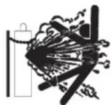
7.b. Always keep cylinders in an upright position securely chained to an undercarriage or fixed support.
7.c. Cylinders should be located:
- Away from areas where they may be struck or subjected to physical damage.
- A safe distance from arc welding or cutting operations and any other source of heat, sparks, or flame.
7.d. Never allow the electrode, electrode holder or any other electrically "hot" parts to touch a cylinder.
7.e. Keep your head and face away from the cylinder valve outlet when opening the cylinder valve.
7.f. Valve protection caps should always be in place and hand tight except when the cylinder is in use or connected for use.
7.g. Read and follow the instructions on compressed gas cylinders, associated equipment, and CGA publication P-I, "Precautions for Safe Handling of Compressed Gases in Cylinders," available from the Compressed Gas Association, 14501 George Carter Way Chantilly, VA 20151.

FOR ELECTRICALLY POWERED EQUIPMENT.

8.a. Turn off input power using the disconnect switch at the fuse box before working on the equipment.
8.b. Install equipment in accordance with the U.S. National Electrical Code, all local codes and the manufacturer's recommendations.
8.c. Ground the equipment in accordance with the U.S. National Electrical Code and the manufacturer's recommendations.
Refer to
http://www.lincolnelectric.com/safety for additional safety information.
PRODUCT DESCRIPTION....3
SPECIFICATIONS ....3
CART ASSEMBLY INSTRUCTIONS....3
WELDER MOUNTING INSTRUCTIONS....7
GAS CYLINDER MOUNTING INSTRUCTIONS....8
OPERATING INSTRUCTIONS ....8
PARTS LIST....PARTS.LINCOLNELECTRIC.COM
CONTENT/DETAILS MAY BE CHANGED OR UPDATED WITHOUT NOTICE. FOR MOST CURRENT INSTRUCTION MANUALS, GO TO PARTS.LINCOLNELECTRIC.COM.
PRODUCT DESCRIPTION
The K520 and K520-1 Utility Carts are designed for mounting and transporting the Lincoln family of small SP, Weld-Pak, and small AC type welders. They have provisions for mounting a single gas cylinder when used with a SP type welder or Weld-Pak type.
These units are compact enough for home use, yet rugged enough for commercial use. They are easily moved on front swivel casters, and large, easy rolling rear wheels. A unique feature is the adjustable height handle, which allows comfortable and convenient operation by any operator. In addition to space for a welder and gas bottle, space has been provided for carrying the operator's tools and welding accessories.
SPECIFICATIONS
Cylinder Capacity:
| Maximum Outside Diameter: | 8.1" (20.6cm) |
| Maximum Height: | 46" (117cm) |
| Maximum Weight: | 100 lbs (45kg) |
| Maximum Capacity: | |
| Welder alone: | 100 lbs (45kg) |
| Welder with Gas Cylinder: | 200 lbs (90kg) |
K520 CART ASSEMBLY iSTRUCTIONS
Parts Required:
| Part Number | Description | Required |
| CF000141 | 1/4-20 x 1.50 screw | 2 |
| CF000017 | 1/4-20 nut | 2 |
| E106A-2 | 1/4 inch Lockwasher | 2 |
| S9225-4 | 10-24 x .375 Screw | 7 |
Tools required for Utility Cart assembly:
Phillips Screwdriver (#I)
7/16 inch wrench
Pliers
Step 1
Carefully remove the cart, gussets, handle, and the loose parts bag from the carton. Check the parts in the loose parts bag against the list provided. Note that some parts are used for assembling the cart, while those in the separate bag are for attaching your welder to the cart.
Leave all screws slightly loose until step 8.
Step 2 (See Figure 1)
Carefully unfold the cart by raining the Front Upright to the vertical position. Insert one 10-24 x .375 screw through the lower front. The Front Upright will now stay in the vertical position.
FIGURE 1

natural_image
Technical line drawing of a mechanical cart with wheels and a handle, showing motion direction (no text or symbols)Step 3 (See Figure 2)
Raise up the rear portion of the Top Shelf, and lift the Rear Upright. As the Rear Upright is raised, the Tank Support will become vertical. Insert the tabs in the bottom of the Tank Support into the corresponding slots in the Bottom Shelf. Lower the Top Shelf until it is supported by the rear upright.
FIGURE 2

natural_image
Line drawing of a wheeled cart with wheels and a handle, showing motion direction (no text or symbols)Step 4 (See Figure 3)
With the Rear Shelf still raised, install the right hand Vertical Gusset alongside the Tank Support. Begin by placing the tab in the bottom of the Vertical Gusset into the slot in the Bottom Shelf, just to the right of the Rear Upright. Insert the Vertical Gusset's upper tab into the Rear Upright. Repeat this with the left hand Vertical Gusset. Lower the Top Shelf until it is supported by the Rear Upright.
FIGURE 3

natural_image
Technical line drawing of a mechanical device with wheels and a handle (no text or symbols)Step 5 (See Figure 4)
Screw the Top Shelf and the Rear Support together using 10-24 x .375 screws. For easiest assembly, use two screws to first secure the sides of the Top Shelf to the Rear Upright. Next, put one more screw through the top of the Top Shelf, into the Rear Support.
FIGURE 4

natural_image
Technical line drawing of a wheeled cart with wheels and a handle, showing mechanical components and wiring (no text or symbols)Step 6 (See Figure 5)
Secure the Rear Upright to the Bottom Shelf using one 10-24 x .375 screw.
FIGURE 5

natural_image
Technical line drawing of a wheeled cart with wheels and side-mounted sensors (no text or symbols)Step 7 (See Figure 5)
Place the remaining two screws through the sides of the Top Shelf into the Front Upright.
Step 8
Tighten all eleven screws (7 inserted by the customer, 4 inserted at the factory) used to hold the Utility Cart together.
Step 9 (See Figure 7)
Insert the Handle as shown. Slide it into the Front Upright, adjusting it to a comfortable position. Secure the handle using the two 1/4-20 x 1.50 screws by aligning the hole in the end of the handle with one set of holes in the Front Upright, and sliding the screws through the holes. Secure the screws with one lockwasher and one nut on each screw.
FIGURE 7

natural_image
Line drawing of a hand-pulling cart with wheels and handle (no text or symbols)The Utility Cart is now fully assembled. Refer to the Welder Mounting Instructions for mounting your specific welder.
K520-1 CART ASSEMBLY iNSTRUCTIONS
Parts Required:
| Part Number | Description | Required |
| CF000141 | 1/4-20 x 1.50 screw | 2 |
| CF000017 | 1/4-20 nut | 2 |
| E106A-2 | 1/4 inch Lockwasher | 2 |
| S9225-4 | 10-24 x .375 Screw | 12 |
Tools required for Utility Cart assembly:
Phillips Screwdriver (#I)
7/16 inch wrench
Pliers
Step 1
Carefully remove the cart, gussets, handle, and the loose parts bag from the carton. Check the parts in the loose parts bag against the list provided. Note that some parts are used for assembling the cart, while those in the separate bag are for attaching your welder to the cart.
Leave all screws slightly loose until step 8.
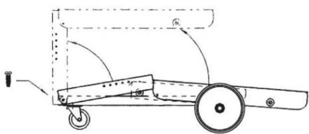
Step 2 (See Figure 8)
Carefully unfold the cart by raining the Front Upright to the vertical position. Insert one 10-24 x .375 screw through the lower front. The Front Upright will now stay in the vertical position.
FIGURE 8
natural_image
Technical line drawing of a mechanical cart with wheels and a handle, showing motion arrows (no text or symbols)Step 3 (See Figure 9)
Raise up the rear portion of the Top Shelf, and lift the Rear Upright. As the Rear Upright is raised, the Tank Support will become vertical. Insert the tabs in the bottom of the Tank Support into the corresponding slots in the Bottom Shelf. Lower the Top Shelf until it is supported by the rear upright.
FIGURE 9

natural_image
Technical line drawing of a mechanical cart with wheels and a handle, showing motion direction (no text or symbols)Step 4 (See Figure 10)
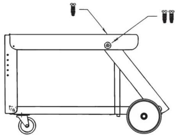
Screw the Top Shelf and the Rear Support together using 10-24 x .375 screws. For easiest assembly, use two screws to first secure the sides of the Top Shelf to the Rear Upright. Next, put one more screw through the top of the Top Shelf, into the Rear Support.
FIGURE 10
natural_image
Technical line drawing of a wheeled cart with wheels and a handle, showing no text or symbolsStep 5 (See Figure 11)
Secure the Rear Upright to the Bottom Shelf using one 10-24 x .375 screw. Place the remaining two screws through the sides of the Top Shelf into the Front Upright.
FIGURE 11

natural_image
Line drawing of a wheeled cart with wheels and two small components attached (no text or symbols)Step 6 (See Figure 12)
Insert Vertical Gussets into slots of bottom shelf and secure to both Top Shelf and Bottom shelf with two 10-24 x .375 screws each.
FIGURE 12

natural_image
Line drawing of a two-wheeled cart with wheels and a vertical guide bar (no text or symbols)Step 7 (See Figure 13)
Secure Rear Upright to the Bottom Shelf using one 10-24 x .375 screw.
FIGURE 13

natural_image
Line drawing of a two-wheeled cart or container with wheels and a handle, no text or symbols presentStep 8
Tighten all sixteen screws (12 inserted by the customer, 4 inserted at the factory) used to hold the Utility Cart together.
Step 9 (See Figure 14 - NOTE: Not necessary for Power MIG 215 MP)
Insert the Handle as shown. Slide it into the Front Upright, adjusting it to a comfortable position. Secure the handle using the two 1/4-20 x 1.50 screws by aligning the hole in the end of the handle with one set of holes in the Front Upright, and sliding the screws through the holes. Secure the screws with one lockwasher and one nut on each screw.
FIGURE 14

natural_image
Line drawing of a hand-drawn cart with wheels and a handle, no text or symbols presentThe Utility Cart is now fully assembled. Refer to the Welder Mounting Instructions for mounting your specific welder.
WELDER MOUNTING INSTRUCTIONS
Small SP welder and Weldpak to the Utility Cart
Parts Required:
| Part Number | Description | Required |
| S19528 | Mounting Clip | 3 |
| CF000014 | 1/4-20 x .75 screw | 3 |
| T9860-6 | Lock Washer | 3 |
| CF000017 | 1/4-20 Hex Nut | 3 |
Refer to Figure 8 while mounting your welder.
Step 1
Secure one Welder Clip in position with a bolt, lockwasher, and nut Note that the overhanging edge of the Welder Clip must face toward the door of the welder, so that the welder covers the bolt head when installed.
Step 2
Position your welder as shown. Open the welder door, and slide the welder over the bolt head, engaging the lower lip of the welder with the overhanging edge of the Welder Clip.
Step 3
On the opposite side of the welder, remove the front and rear self-tapping screws which secure the case side. Attach two Welder Clips to the case side, using the same holes and screws. The overhanging edge of the Welder Clip must face away from the welder.
Step 4
Adjust the welder position so that the holes in the Welder Clips line up with holes in the Utility Cart as shown. Secure the clips to the Cart with two bolts, two lockwashers, and two nuts.

CAUTION
THE HANDLE ON YOUR WELDER IS NOT TO BE USED FOR LIFTING WHEN THE WELDER IS ATTACHED TO THE UTILITY CART. THE HANDLE IS FOR LIFTING THE WELDER ONLY! DO NOT LIFT BY THE HANDLE WHEN THE CART IS ATTACHED!
See gas cylinder mounting instructions if a cylinder is to be used.
FIGURE 15

natural_image
Technical diagram of a mechanical assembly with cross-sectional views and component outlines (no text or labels)AC-225-C Welder to the Utility Cart
Parts Required:
Part Number Description Required
S8025-54 1/4-20 x 1.25 4
Screw
Refer to Figure 16 while mounting your AC-225-C welder.
Position the AC-225-C as shown. Attach the AC-225-C with four 1/4 x 1 1/4 in. Self-tapping screws from underneath using the holes provided in the base of the AC-225-C and the Utility Cart.
If desired, the chain and buckle/strap assemblies may be removed, since a gas bottle is not required when welding with an AC-225-C.

CAUTION
THE HANDLE ON YOUR AC-225-C IS NOT TO BE USED FOR LIFTING WHEN THE AC-225C IS ATTACHED TO THE UTILITY CART. THE HANDLE IS FOR LIFTING THE AC-225-C ONLY! DO NOT LIFT BY THE HANDLE WHEN THE CART IS ATTACHED.

FIGURE 16

natural_image
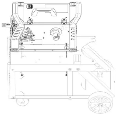
Line drawing of a manual cart with wheels and a side-mounted fan (no text or symbols)Power MIG 215 MPi Mounting (For K520-1 Only)
Parts Required:
| Part Number | Description | Required |
| CF000012 | 1/4-20 HHCS | 2 |
| S25676-4 | 1/4-20 Flange Nut | 2 |
Step 1
Remove Handle from K520-1 Utility Cart.
Step 2
Align the Power MIG 215MPi as shown in figure below and fasten with 14 -20 HHCS and 14 -20 Flange Nut. Door will need to be opened to access base embosses to mount to Top Shelf.
natural_image
Technical line drawing of a mechanical device with wheels and internal components (no text or symbols)GAS CYLINDER MOUNTING INSTRUCTIONS

WARNING
CYLINDER could explode if damaged.
- Keep cylinder upright and chained to a support.
- Keep cylinder away from areas where it could be damaged.
- Never lift welder with cylinder attached.
- Never allow the welding electrode to touch the cylinder.
- Keep cylinder away from welding and other live electrical circuits.
Gas Cylinders Less Than 15 inches (40cm) Tall
Set the cylinder upright on the rear of the Bottom Shelf. Secure in place with the Strap and Buckle Assembly. The cylinder must be held tightly against the Tank Support. The chain is not used.
Gas Cylinders Greater Than 15 inches (40cm) Tall
Set the cylinder upright on the rear of the Bottom Shelf. Secure in place by looping the Chain around the bottle, and passing the end of the chain through the keyhole slot in the Top Shelf. Lock the link that gives the tightest fit around the bottle in the narrow slot. Secure the lower portion of the bottle with the strap and Buckel Assembly. Both the Chain and the Strap Assembly must be used.
OPERATING INSTRUCTIONS
The Utility Cart is designed for hand moving only. Do not attempt to pull the cart with any mechanized vehicle.
Use the cart on a level surface only. Moving the cart over steep inclines could cause the cart to roll out of control, or tip over. Either situation could result in damage to the cart, welder, or injury to the operator.
The Utility Cart is designed to work only with the Lincoln products listed below. Use with other welders or equipment could cause overloading, or result in unstable operations.
Products Supported on K520 and K520-1:
AC225-C
INVERTEC V160-S, INVERTEC V160-T
INVERTEC V205T AC/DC
PRO-CUT 25
Pro-MIG 175, Pro-Core 100
Products Supported on K520-1 Only:
Power MIG 215MPi

GENERAL ASSEMBLY
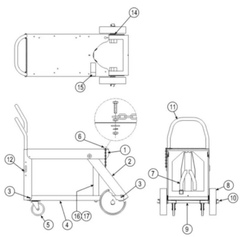
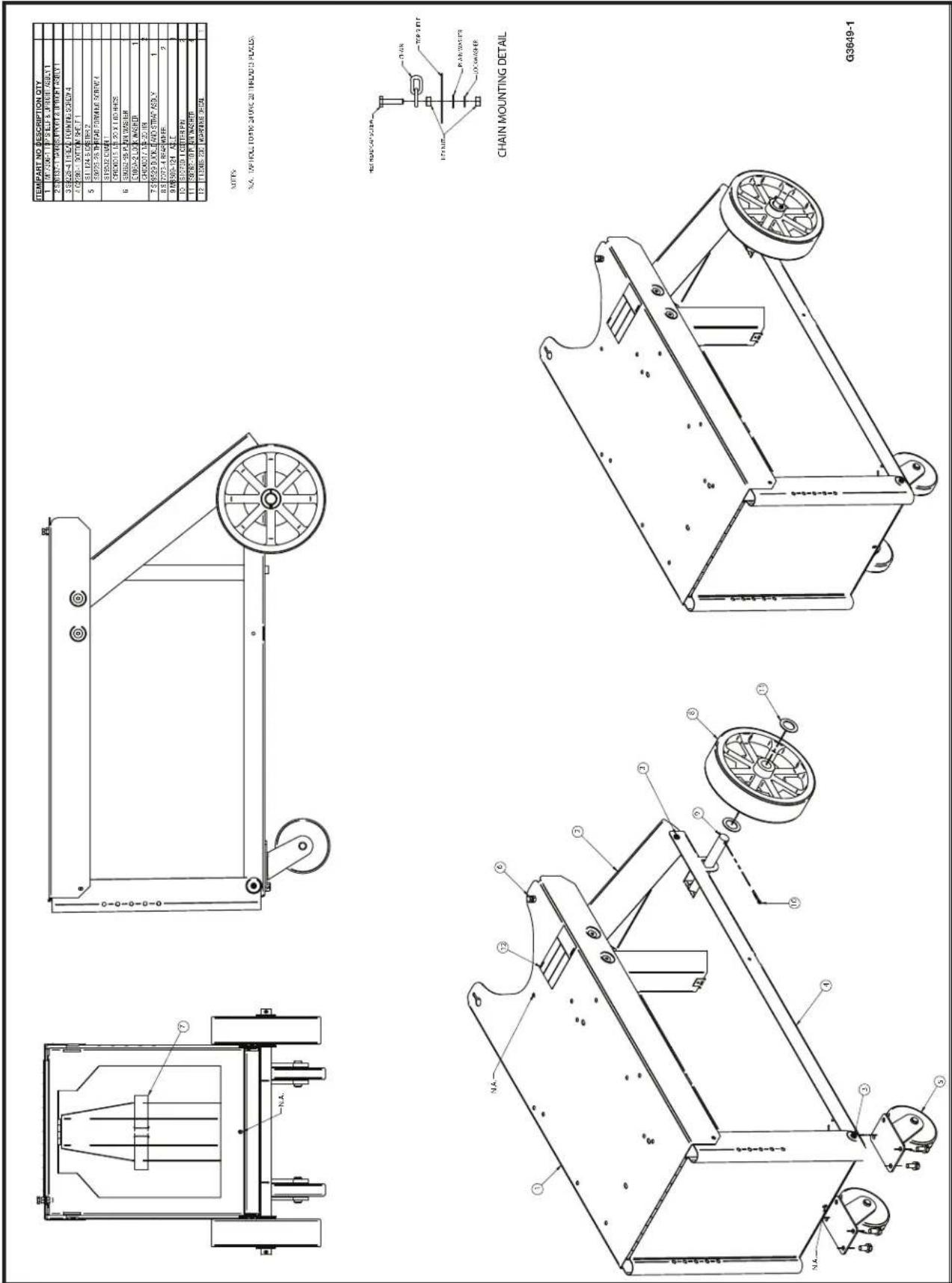
N.A. TAPHOLE TO 10C 24 (NC) 28 THFLND (3 FLICES).
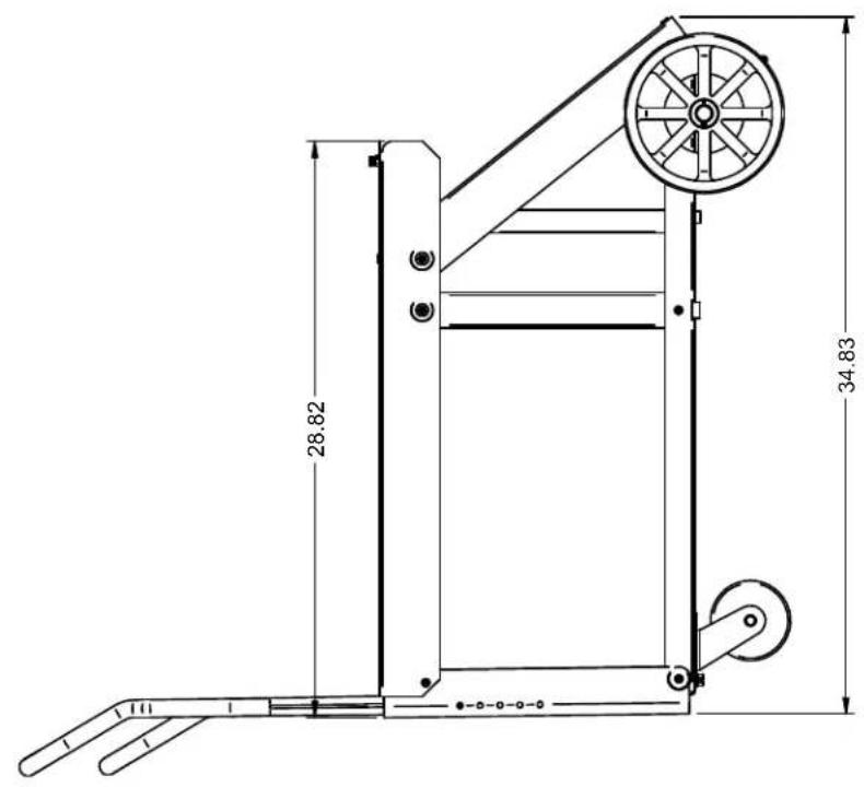
DIMENSION PRINT

This page intentionally left blank.
 |  |  |  |
| WARNING | Do not touch electrically live parts or electrode with skin or wet clothing.Insulate yourself from work and ground. | Keep flammable materials away. | Wear eye, ear and body protection. |
| SpanishAVISO DE PRECAuCION | No toque las partes o los electrodos bajo carga con la piel o ropa moja-da.Aislese del trabajo y de la tierra. | Mantenga el material combustible fuera del área de trabajo. | Protéjase los ojos, los oídos y el cuerpo. |
| FrenchATTENTION | Ne laissez ni la peau ni des vête-ments mouillés entrer en contact avec des pièces sous tension.Isolez-vous du travail et de la terre. | Gardez à l'écart de tout matériel inflammable. | Protégez vos yeux, vos oreilles et votre corps. |
| GermanWARNuNG | Berühren Sie keine stromführenden Teile oder Elektroden mit Ihrem Körper oder feuchter Kleidung!Isolieren Sie sich von den Elektroden und dem Erdboden! | Entfernen Sie brennbarres Material! | Tragen Sie Augen-, Ohren- und Kör-perschutz! |
| PortugueseATENÇÃO | Não toque partes elétricas e elec-trodos com a pele ou roupa molha-da.Isole-se da peça e terra. | Mantenha inflamáveis bem guarda-dos. | Use proteção para a vista, ouvido e corpo. |
| Japanese注意事項 | 通電中の電気部品、又は溶材にヒフやぬれた布で触れないこと。施工物やアースから身体が絶縁されている様にして下さい。 | 燃えやすいものの側での溶接作業は絶対にしてはなりません。 | 目、耳及び身体に保護具をして下さい。 |
| Chinese警告 | 皮肤或濕衣物切勿接觸帶電部件及鉀條。使你自己與地面和工件絶縁。 | 把一切易燃物品移離工作場所。 | 佩戴眼、耳及身體勞動保護用具。 |
| Korean위험 | 전도체나 용접봉을 잦은 청립 또는 피부로 절대 접촉치 마십시오.모재와 접지를 접촉치 마십시오. | 인화성 물질을 접근 시키지 마시요. | 눈, 귀와 몇에 보호장구들 착용하십시오. |
| Arabicتحذير | لا تلمس الاجزاء التي يسری فها التيار الكهربائي أو الالكترود بجلد الجسم أو بالعلابس المبللة بال permاء.UGH عازلا على جسمك خلال العمل. | UGH #: depicting copad القابلة للاشتمال في مكان بعید. | UGH أبوات وملابس واقية على عينيك وأدنيك.ujessk. |
READ AND UNDERSTAND THE MANUFACTURER'S INSTRUCTION FOR THIS EQUIPMENT AND THE CONSUMABLES TO BE USED AND FOLLOW YOUR EMPLOYER'S SAFETY PRACTICES.
CUSTOMER ASSISTANCE POLICY
The business of The Lincoln Electric Company is manufacturing and selling high quality welding equipment, consumables, and cutting equipment. Our challenge is to meet the needs of our customers and to exceed their expectations. On occasion, purchasers may ask Lincoln Electric for advice or information about their use of our products. We respond to our customers based on the best information in our possession at that time. Lincoln Electric is not in a position to warrant or guarantee such advice, and assumes no liability, with respect to such information or advice. We expressly disclaim any warranty of any kind, including any warranty of fitness for any customer's particular purpose, with respect to such information or advice. As a matter of practical consideration, we also cannot assume any responsibility for updating or correcting any such information or advice once it has been given, nor does the provision of information or advice create, expand or alter any warranty with respect to the sale of our products.
Lincoln Electric is a responsive manufacturer, but the selection and use of specific products sold by Lincoln Electric is solely within the control of, and remains the sole responsibility of the customer. Many variables beyond the control of Lincoln Electric affect the results obtained in applying these types of fabrication methods and service requirements.
Subject to Change – This information is accurate to the best of our knowledge at the time of printing. Please refer to www.lincolnelectric.com for any updated information.
WELD FUME CONTROL EQUIPMENT
The operation of welding fume control equipment is affected by various factors including proper use and positioning of the equipment, maintenance of the equipment and the specific welding procedure and application involved. Worker exposure level should be checked upon installation and periodically thereafter to be certain it is within applicable OSHA PEL and ACGIH TLV limits.

THE LINCOLN ELECTRIC COMPANY
22801 St. Clair Avenue • Cleveland, OH • 44117-1199 • U.S.A.
Phone: +1.216.481.8100 • www.lincolnelectric.com
- THANK YOU FOR SELECTING A QUALITY PRODUCT BY LINCOLNELECTRIC.
- PLEASE EXAMINE CARTON AND EQUIPMENT FOR DAMAGE IMMEDIATELY
- SAFETY DEPENDS ON YOU
- WARNING
- CAUTION
- KEEP YOUR HEAD OUT OF THE FUMES.
- WEAR CORRECT EYE, EAR & BODY PROTECTION
- SPECIAL SITUATIONS
- Additional precautionary measures
- SECTION A: WARNINGS
- CALIFORNIA PROPOSITION 65 WARNINGS
- FOR ENGINE POWERED EQUIPMENT.
- ELECTRIC AND MAGNETIC FIELDS MAY BE DANGEROUS
- ELECTRIC SHOCK CAN KILL.
- ARC RAYS CAN BURN.
- WELDING AND CUTTING SPARKS CAN CAUSE FIRE OR EXPLOSION.
- CYLINDER MAY EXPLODE IF DAMAGED.
- FOR ELECTRICALLY POWERED EQUIPMENT.
- PRODUCT DESCRIPTION
- SPECIFICATIONS
- Tools required for Utility Cart assembly:
- Step 1
- Step 2 (See Figure 1)
- Step 3 (See Figure 2)
- Step 4 (See Figure 3)
- Step 5 (See Figure 4)
- Step 6 (See Figure 5)
- Step 7 (See Figure 5)
- Step 8
- Step 9 (See Figure 7)
- K520-1 CART ASSEMBLY iNSTRUCTIONS
- Step 2 (See Figure 8)
- Step 3 (See Figure 9)
- Step 4 (See Figure 10)
- Step 5 (See Figure 11)
- Step 6 (See Figure 12)
- Step 7 (See Figure 13)
- Step 9 (See Figure 14 - NOTE: Not necessary for Power MIG 215 MP)
- WELDER MOUNTING INSTRUCTIONS
- Step 2
- Step 3
- Step 4
- AC-225-C Welder to the Utility Cart
- Power MIG 215 MPi Mounting (For K520-1 Only)
- GAS CYLINDER MOUNTING INSTRUCTIONS
- CYLINDER could explode if damaged.
- Gas Cylinders Less Than 15 inches (40cm) Tall
- Gas Cylinders Greater Than 15 inches (40cm) Tall
- OPERATING INSTRUCTIONS
- Products Supported on K520 and K520-1:
- Products Supported on K520-1 Only:
- GENERAL ASSEMBLY
- CUSTOMER ASSISTANCE POLICY
- WELD FUME CONTROL EQUIPMENT
Brand : LINCOLN ELECTRIC
Model : Utility Cart
Category : Utility cart