
PCS2534 - Flat Panel Mount Chief - Free user manual and instructions
Find the device manual for free PCS2534 Chief in PDF.


| Product Type | Flat Panel Mount |
| Brand | Chief |
| Model | PCS2534 |
| Mounting Pattern (VESA) | Compatible with VESA 200x200, 400x200, 400x400 mm |
| Maximum Screen Size | 32 to 84 inches |
| Weight Capacity | Up to 175 lbs (79 kg) |
| Tilt Adjustment | +5° to -15° |
| Swivel Adjustment | ±90° |
| Level Adjustment | ±3° |
| Mounting Type | Fixed mount with lateral shift |
| Material | Steel, aluminum |
| Color | Black |
| Included Hardware | Mounting brackets, bolts, spacers, level |
| Stud Spacing Required | 16-24 inches (406-610 mm) on center |
| Dimension (Mount) | 31.5 x 19.7 x 1.5 inches (800 x 500 x 38 mm) |
| Weight (Mount) | Approx. 22 lbs (10 kg) |
| Installation Type | Wall mount (wood stud or concrete) |
| Maintenance & Cleaning | Wipe with a dry or slightly damp cloth. Avoid solvent cleaners. |
| Safety Standards | UL listed, TUV tested |
| Spare Parts & Repairability | Contact Chief customer service for replacement parts; mount is not user serviceable. |
| Warranty | 10 years |
Frequently Asked Questions - PCS2534 Chief
User questions about PCS2534 Chief
0 question about this device. Answer the ones you know or ask your own.
Ask a new question about this device
Download the instructions for your Flat Panel Mount in PDF format for free! Find your manual PCS2534 - Chief and take your electronic device back in hand. On this page are published all the documents necessary for the use of your device. PCS2534 by Chief.
USER MANUAL PCS2534 Chief
INSTALLATION INSTRUCTIONS

natural_image
Technical line drawing of a mechanical bracket assembly (no text or symbols)Single Ceiling Mount
DISCLAIMER
Milestone AV Technologies, Inc., and its affiliated corporations and subsidiaries (collectively, "Milestone"), intend to make this manual accurate and complete. However, Milestone makes no claim that the information contained herein covers all details, conditions or variations, nor does it provide for every possible contingency in connection with the installation or use of this product. The information contained in this document is subject to change without notice or obligation of any kind. Milestone makes no representation of warranty, expressed or implied, regarding the information contained herein. Milestone assumes no responsibility for accuracy, completeness or sufficiency of the information contained in this document.

IMPORTANT WARNINGS AND TIONS!

WARNING: A WARNING alerts you to the possibility of serious injury or death if you do not follow the instructions.

CAUTION: A CAUTION alerts you to the possibility of damage or destruction of equipment if you do not follow the corresponding instructions

WARNING: Failure to read, thoroughly understand, and follow all instructions can result in serious personal injury, damage to equipment, or voiding of factory warranty! It is the installer's responsibility to make sure all components are properly assembled and installed using the instructions provided.

WARNING: Failure to provide adequate structural strength for this component can result in serious personal injury or damage to equipment! It is the installer's responsibility to make sure the structure to which this component is attached can support five times the combined weight of all equipment. Reinforce the structure as required before installing the component.

WARNING: Exceeding the weight capacity can result in serious personal injury or damage to equipment! It is the installer's responsibility to make sure the combined weight of all components located between the supporting structure and mount does not exceed 200 lbs (90.7 kg).
- The weight capacity of the mount may be LIMITED to the lowest capacity of any other component located between the mount and the supporting structure!
Chief® and ClickConnect™ are trademarks of Milestone AV Technologies, Inc. All rights reserved.
DIMENSIONS
![1-½NPT [31.75] 1.25 [104.03] 4.10](/content/2026/05/1087445/images/5699632920188a15dd717700b0c4a5aabcba160f8fce8fb0975a2c176c05e3dc.jpg)
NOTE: CUSTOM INTERFACE BRACKET NOT SHOWN. THE CUSTOM INTERFACE BRACKET NEEDED FOR DISPLAY WILL ADD BETWEEN 1/2"AND 2" IN DEPTH AND MAY AFFECT LOCATION OF DISPLAY ON MOUNT.
WEIGHT CAPACITY: 200 LBS HEIGHT ADJUSTMENT: 0° TILT/ROLL/YAW: +5°, -20°/ ± 2°/ +0° MEASUREMENTS IN: [MILLIMETERS] INCHES
![[16.66] .66 [19.69] 78 41.32 1.63 [396.88] 15.63 [41.32] 1.63 [297.90] 11.73 [413.30] 16.27](/content/2026/05/1087445/images/b02e530f1f935ba1cebe05e66c1d7f4f38f45b2c6111407abacc21e70c16ac36.jpg)
![[84.17] 3.31 [203.17] 8.00](/content/2026/05/1087445/images/8ddd337be8e9400fd70947b5918aad442196558cd633f59c328b8f2530b78db3.jpg)
LEGEND
 | Tighten Fastener |
| Apretar elemento de fijación | |
| Befestigungsteil festziehen | |
| Apertar fixador | |
| Serrare il fissaggio | |
| Bevestiging vastdraaien | |
| Serrez les fixations | |
 | Loosen Fastener |
| Aflojar elemento de fijación | |
| Befestigungsteil lösen | |
| Desapertar fixador | |
| Allentare il fissaggio | |
| Bevestiging losdraaien | |
| Desserrez les fixations | |
 | Phillips Screwdriver |
| Destornillador Phillips | |
| Kreuzschlitzschraubendreher | |
| Chave de fendas Phillips | |
| Cacciavite a stella | |
| Kruiskopschroevendraaier | |
| Tournevis à pointe cruciforme | |
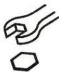 | Open-Ended Wrench |
| Llave de boca | |
| Gabelschlüssel | |
| Chave de bocas | |
| Chiave a punte aperte | |
| Steeksleutel | |
| Clé à fourche | |
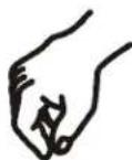 | By Hand |
| A mano | |
| Von Hand | |
| Com a mão | |
| A mano | |
| Met de hand | |
| À la main | |
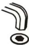 | Hex-Head Wrench |
| Llave de cabeza hexagonal | |
| Sechskantschlüssel | |
| Chave de cabeça sextavada | |
| Chiave esagonale | |
| Zeskantsleutel | |
| Clé à tête hexagonale |


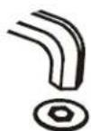
TOOLS REQUIRED FOR INSTALLATION
natural_image
Simple black-and-white diagram of a box with a scroll inside, showing an arrow indicating rotation or movement (no text or symbols)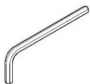
5/32" (Provided)
PARTS

natural_image
Simple black-and-white icon of an open box with a curved arrow indicating rotation or delivery (no text or symbols)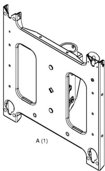
natural_image
Technical line drawing of a metal frame structure with mounting holes and mounting brackets (no text or symbols)
INSTALLATION

WARNING: FAILURE TO PROVIDE ADEQUATE STRUCTURAL STRENGTH FOR THIS COMPONENT CAN RESULT IN SERIOUS PERSONAL INJURY OR DAMAGE TO EQUIPMENT! It is the installer's responsibility to make sure the structure to which this component is attached can support five times the combined weight of all equipment. Reinforce the structure as required before installing the component.
Attaching Mount to NPT Pipe

CAUTION: Watch for pinch points. Do not place fingers between moveable parts.
- Thread the mount (A) onto the existing 1-1/2" NPT pipe until tight. (See Figure 1)
- Using the 5/32" hex head wrench (B) tighten the set screw to prevent movement of the mount. (See Figure 1)

Figure 1
Attaching Interface Bracket to Display
- Attach interface bracket to display following instructions included with interface bracket kit.
Attaching Displays to Mount
- While supporting both sides of display, align four mounting buttons on display or interface bracket with four mounting holes in mount. (See Figures 2, 3 and 4)

Figure 2

WARNING: DISPLAY MAY WEIGH IN EXCESS OF 40 LBS! Always use two people and proper lifting techniques when installing or positioning display on mount.
- Lower display into place listening for audible "click" to ensure recessed area of mounting buttons are properly seated in lower area of mounting holes and ClickConnect mechanism has engaged. (See Fig. 2, 3 and 4)

Figure 3

WARNING: IMPROPER INSTALLATION CAN LEAD TO DISPLAY FALLING CAUSING SERIOUS PERSONAL INJURY OR DAMAGE TO EQUIPMENT! Ensure mounting buttons are completely engaged in mounting holes.
NOTE: Holes are provided in the faceplate for use with a padlock or similar locking device, if desired. In addition, the pin and nut may be removed from the upper holes and moved to the lower holes for use as a more permanent locking device. (See Figure 4).

Figure 4
Removing Display
- Disconnect all power/audio/video cables.
- Remove bolt or padlock from faceplate (if used). (See Figure 5)
NOTE: The pin may have been used as a more permanent locking device. If so, remove nut and pin and move from the lower holes to the upper holes.
- Pull back on flag on upper mounting hole and press pin down into "Open" position. (See Figure 5)

WARNING: THE DISPLAY MAY WEIGH IN EXCESS OF 40 LBS EACH! Always use two people and proper lifting techniques when installing or positioning display.
- Carefully lift display from mount.
- Lift up on pin and place flag back against faceplate to return it to "Closed" position. (See Figure 5)

Figure 5
Adjusting Display

CAUTION: Watch for pinch points. Do not place fingers between moveable parts.
Adjusting Roll
- Using a 9/16" wrench, loosen the Nylock roll adjustment nut on back of mounting plate. (See Figure 6)
- Tilt the faceplate left or right as required.
- Tighten nut.
NOTE: Do NOT overtighten fasteners.
Adjusting Pitch
- Adjust display to the desired pitch.
- Using the 5/32" hex head wrench (B), tighten the pitch adjustment screw to hold mount in position. (See Figure 6)

Figure 6
PCS SERIES
Installation Instructions


Brand : Chief
Model : PCS2534
Category : Flat Panel Mount