
HFSTS - Flat Panel Mount Chief - Free user manual and instructions
Find the device manual for free HFSTS Chief in PDF.


| Product Type | Flat Panel Tilt Mount |
| Compatible Screen Sizes | 37" to 80" |
| Weight Capacity | 100 lbs (45.4 kg) |
| VESA Compatibility | 200x200 mm to 600x400 mm |
| Tilt Range | +9° to -2° |
| Material | Steel |
| Finish | Black Powder Coat |
| Mounting Options | Single or dual wood stud, concrete |
| Distance from Wall (Min/Max) | 1.8" / 16.0" (4.6 cm / 40.6 cm) |
| Installation Hardware Included | Yes |
| Certifications | UL Listed |
| Warranty | 5 Years |
| Dimensions (WxHxD) | 31.5" x 17.7" x 1.8" (80 x 45 x 4.6 cm) |
| Weight | 15 lbs (6.8 kg) |
| Clean and Maintenance | Wipe with a dry cloth; do not use solvents |
| Safety Warning | Do not exceed weight capacity; ensure proper wall anchoring |
| Spare Parts Availability | Contact Chief customer service for replacement hardware |
| Repairability | FAANG mount design allows easy replacement of parts |
| General Information | Designed for professional and residential use; VESA compliant |
Frequently Asked Questions - HFSTS Chief
User questions about HFSTS Chief
0 question about this device. Answer the ones you know or ask your own.
Ask a new question about this device
Download the instructions for your Flat Panel Mount in PDF format for free! Find your manual HFSTS - Chief and take your electronic device back in hand. On this page are published all the documents necessary for the use of your device. HFSTS by Chief.
USER MANUAL HFSTS Chief
INSTALLATION INSTRUCTIONS

natural_image
3D rendering of a vertical metal post with a flat support and mounting base (no text or symbols)Column-mounted Tablet Floor Stand
DISCLAIMER
Legrand | AV and its affiliated corporations and subsidiaries (collectively "Legrand | AV"), intend to make this manual accurate and complete. However, Legrand | AV makes no claim that the information contained herein covers all details, conditions or variations, nor does it provide for every possible contingency in connection with the installation or use of this product. The information contained in this document is subject to change without notice or obligation of any kind. Legrand | AV makes no representation of warranty, expressed or implied, regarding the information contained herein. Legrand | AV assumes no responsibility for accuracy, completeness or sufficiency of the information contained in this document.
Chief® is a registered trademark of Legrand AV Inc.
DEFINITIONS
MOUNTING SYSTEM: A MOUNTING SYSTEM is the primary Chief product to which an accessory and/or component is attached.
ACCESSORY: AN ACCESSORY is the secondary Chief product which is attached to a primary Chief product, and may have a component attached or setting on it.
COMPONENT: A COMPONENT is an audiovisual item designed to be attached or resting on an accessory or mounting system such as a video camera, CPU, screen, display, projector, etc.

WARNING: A WARNING alerts you to the possibility of serious injury or death if you do not follow the instructions.

CAUTION: A CAUTION alerts you to the possibility of damage or destruction of equipment if you do not follow the corresponding instructions.

IMPORTANT SAFETY INSTRUCTIONS

WARNING: Failure to read, thoroughly understand, and follow all instructions can result in serious personal injury, damage to equipment, or voiding of factory warranty! It is the installer's responsibility to make sure all mounting systems are properly assembled and installed using the instructions provided.

WARNING: Failure to provide adequate structural strength for this mounting system can result in serious personal injury or damage to equipment! It is the installer's responsibility to make sure the structure to which this mounting system is attached can support five times the combined weight of all equipment. Reinforce the structure as required before installing the mounting system.

WARNING: Exceeding the weight capacity can result in serious personal injury or damage to equipment! It is the installer's responsibility to make sure the combined weight of all components and accessories attached to mounting system does not exceed 10 lbs (4.5 kg) for the main interface or 18 lbs (8.1 kg) for the entire mount when used with both compatible accessories (not included). See Figure below for details.
NOTE: Both accessories shown may be used together.


WARNING: Use this mounting system only for its intended use as described in these instructions. Do not use attachments not recommended by the manufacturer.

WARNING: Never operate this mounting system if it is damaged. Return the mounting system to a service center for examination and repair.

WARNING: Do not use this mounting system outdoors.

WARNING: RISK OF INJURY TO PERSONS! Do not use this mounting system to support video equipment such as televisions or computer monitors.
--SAVE THESE INSTRUCTIONS--
DIMENSIONS
![R1.00 [25.4] Ø 1.30 [33.0] R.50 [12.7] 48.03 [1220.0] .25 [6.4] 4.00 [101.6] 15.00 [381.0] 15.00 [381.0] 13.00 [330.2] 13.00 [330.2] 61.7 [1566.0] 55.7 [1413.6] 2.83 [71.8] MOUNTED ELECTRONIC EQUIPMENT 36.00 [914.4] WIRE CHASE ACCESS HOLE DETAIL A SCALE 1:3 1.50 [38.1] .50 [12.7] DETAIL B SCALE 1:3](/content/2026/05/1087409/images/bdbbef67edb6017cfa79709c2fd836563e2558a864dfc8cd4871fcb8ff474161.jpg)
LEGEND
 | Tighten Fastener |  | Pencil Mark |
| Apretar elemento de fijación | Marcar con lápiz | ||
| Befestigungsteil festziehen | Stiftmarkierung | ||
| Apertar fixador | Marcar com lápis | ||
| Serrare il fissaggio | Segno a matita | ||
| Bevestiging vastdraaien | Potloodmerkteken | ||
| Serrez les fixations | Marquage au crayon | ||
 | Loosen Fastener |  | Drill Hole |
| Aflojar elemento de fijación | Perforar | ||
| Befestigungsteil lösen | Bohrloch | ||
| Desapertar fixador | Fazer furo | ||
| Allentare il fissaggio | Praticare un foro | ||
| Bevestiging losdraaien | Gat boren | ||
| Desserrez les fixations | Percez un trou | ||
 | Phillips Screwdriver |  | Adjust |
| Destornillador Phillips | Ajustar | ||
| Kreuzschlitzschraubendreher | Einstellen | ||
| Chave de fendas Phillips | Ajustar | ||
| Cacciavite a stella | Regolare | ||
| Kruiskopschroevendraaier | Afstellen | ||
| Tournevis à pointe cruciforme | Ajuster | ||
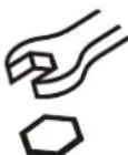 | Open-Ended Wrench |  | Remove |
| Llave de boca | Quitar | ||
| Gabelschlüssel | Entfernen | ||
| Chave de bocas | Remover | ||
| Chiave a punte aperte | Rimuovere | ||
| Steeksleutel | Verwijderen | ||
| Clé à fourche | Retirez | ||
 | By Hand |  | Optional |
| A mano | Opcional | ||
| Von Hand | Optional | ||
| Com a mão | Opcional | ||
| A mano | Opzionale | ||
| Met de hand | Optie | ||
| À la main | En option | ||
 | Hex-Head Wrench |  | Security Wrench |
| Llave de cabeza hexagonal | Llave de seguridad | ||
| Sechskantschlüssel | Sicherheitsschlüssel | ||
| Chave de cabeça sextavada | Chave de segurança | ||
| Chiave esagonale | Chiave di sicurezza | ||
| Zeskantsleutel | Veiligheidssleutel | ||
| Clé à tête hexagonale | Clé de sécurité |
TOOLS REQUIRED FOR INSTALLATION

PARTS

natural_image
Simple line drawing of a 3D rectangular block with a square top and a small circular hole at the top (no text or symbols on the object itself)
natural_image
Simple line drawing of a vertical column cover with no text or symbols![C (1) [Bolt plate] D (2) [Base plate]](/content/2026/05/1087409/images/3ab4632a5c3b7e607f86517c5607622db13252beef702c770f24f4b556722f6a.jpg)

Assembly And Installation
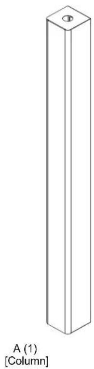
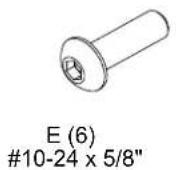
- Partially install six #10-24 x 5/8" button head cap screws (E) into column (A). (See Figure 1)
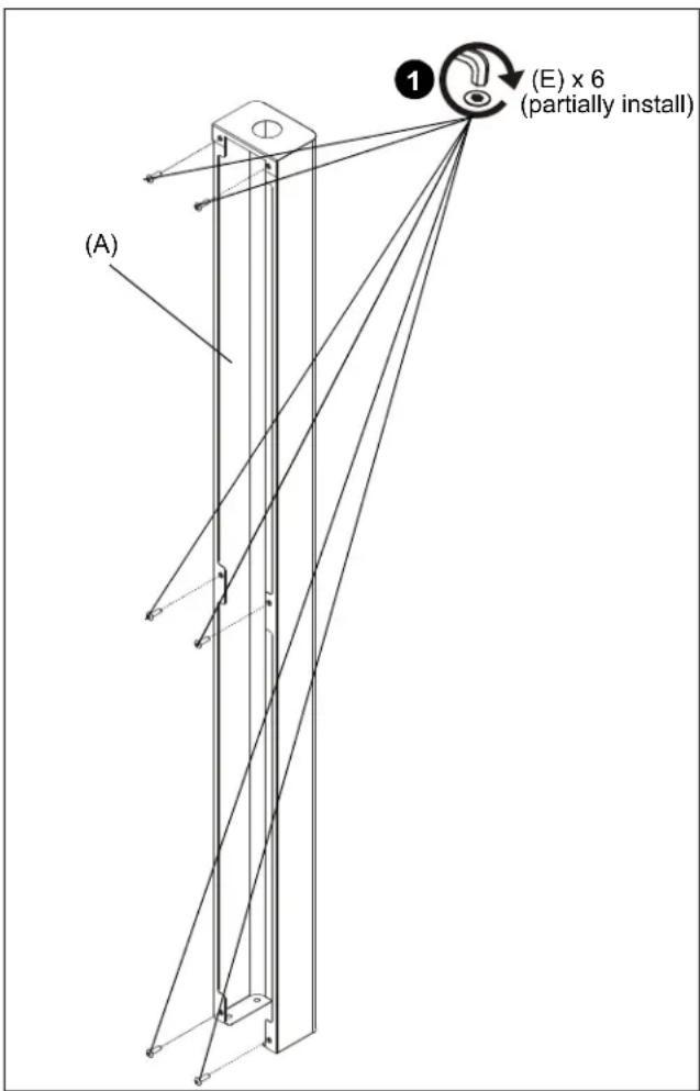
Figure 1
- Install bolt plate (C) inside column (A) channel. (See Figure 2)
- Use four #10-24 x 1/2" flat head cap screws (F) to secure two base plates (D) to column (A) and bolt plate (C). (See Figure 2)
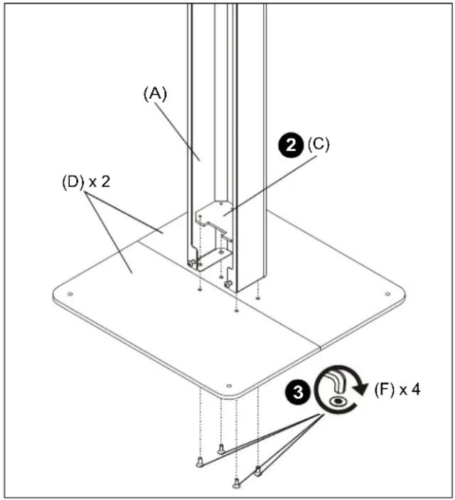
Figure 2

WARNING: Exceeding the weight capacity can result in serious personal injury or damage to equipment! It is the installer's responsibility to make sure the combined weight of all components and accessories attached to mounting system does not exceed 10 lbs (4.5 kg) for the main interface or 18 lbs (8.1 kg) for the entire mount when used with both compatible accessories (not included). See Figure on page 2 for details.
- Use column-mounted tablet nut (provided with column-mounted tablet) to install column-mounted tablet (not included) to column. (See Figure 3)

Figure 3
- Connect cord to bottom of column-mounted tablet. (See Figure 4)
- Install column cover (B) onto column (A) making sure keyholes are onto screws and cable is routed through the bottom gap on cover. (See Figure 4)
- Tighten all screws (F) to secure cover (B) to column (A). (See Figure 4)

Figure 4
Cable Management
- Loosen screws (E) holding cover (B) to column (A) and remove cover (B). (See Figure 5)
- Route component cable(s) using middle and lower openings on cover (B). (See Figure 5)
- Reinstall cover (B) and tighten screws (E) to secure cover (B) to column (A). (See Figure 5)

Figure 5
Bolt to Floor (Optional)
The HFSTS mount may be bolted to the floor for increased security or stability. Hardware is NOT provided for this installation.
IMPORTANT ! : Base plates (D) must be attached to column (A) and bolt plate (C) before being bolted to floor.
- Use base plates (D) as a template to mark holes on floor at desired mounting location.
- Drill holes at marked locations according to instructions of hardware being used for installation. (See Figure 6)
- Use hardware (not included) to secure base plates (D) to floor. (See Figure 6)

Figure 6

CHIEF®
A brand of legrand
8800-003237 Rev01
©2020 Legrand | AV
www.legrandav.com
09/2020
USA/International A 6436 City West Parkway, Eden Prairie, MN 55344
P 800.582.6480 / 952.225.6000
F 877.894.6918 / 952.894.6918
Europe A Franklinstraat 14, 6003 DK Weert, Netherlands
P +31 (0) 495 580 852
F +31 (0) 495 580 845
Asia Pacific A Office No. 918 on 9/F, Shatin Galleria
18-24 Shan Mei Street
Fotan, Shatin, Hong Kong
P 852 2145 4099
F 852 2145 4477


Brand : Chief
Model : HFSTS
Category : Flat Panel Mount