
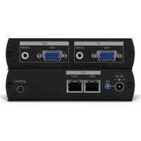
AT-UHD-CLSO-612ED - Video switch Atlona - Free user manual and instructions
Find the device manual for free AT-UHD-CLSO-612ED Atlona in PDF.


| Product Type | HDMI Matrix Switcher |
| Model | AT-UHD-CLSO-612ED |
| Brand | Atlona |
| Dimensions (W x D x H) | 17.3 x 7.2 x 1.7 in (440 x 183 x 43 mm) |
| Weight | 4.4 lbs (2 kg) |
| Power Supply | 100-240V AC, 50/60 Hz, internal |
| Video Standards | HDMI 2.0, HDCP 2.2 |
| Maximum Resolution | 4K@60Hz 4:4:4 |
| Input Ports | 6 x HDMI |
| Output Ports | 12 x HDMI |
| Control Interfaces | RS-232, IR, Ethernet, USB |
| Supported Audio | Dolby TrueHD, DTS-HD Master Audio, PCM |
| EDID Management | Internal EDID emulation and bypass |
| Power Consumption | 25W (typical) |
| Operating Temperature | 32°F to 104°F (0°C to 40°C) |
| Storage Temperature | -4°F to 140°F (-20°C to 60°C) |
| Humidity | 10% to 90% non-condensing |
| Cleaning Instructions | Wipe with a soft, dry cloth. Do not use liquid cleaners. |
| Safety Warnings | Do not expose to rain or moisture. Use only supplied power cord. |
| Spare Parts / Repairability | Contact Atlona support for replacement parts. No user-serviceable parts inside. |
| Certifications | FCC, CE, RoHS |
Frequently Asked Questions - AT-UHD-CLSO-612ED Atlona
User questions about AT-UHD-CLSO-612ED Atlona
0 question about this device. Answer the ones you know or ask your own.
Ask a new question about this device
Download the instructions for your Video switch in PDF format for free! Find your manual AT-UHD-CLSO-612ED - Atlona and take your electronic device back in hand. On this page are published all the documents necessary for the use of your device. AT-UHD-CLSO-612ED by Atlona.
USER MANUAL AT-UHD-CLSO-612ED Atlona
Atlona 6 Input Switcher and Scaler with HDBaseT and Mirrored HDMI Output
AT-UHD-CLSO-612ED
User Manual

Please check http://www.atlona. com/product/AT-UHD-CLSO-
612ED for the most recent
firmware update or manual.
Table of Contents
- Introduction ...... 3
- Package Contents 3
- Features
- Panel Descriptions
a. Front Panel 4
b. Rear Panel 4
- Wall/Rack Mounts 5
- Category Cable 5
- Analog Multi-Format Inputs 6
- Audio Connections 7
- Microphone 8
- On Screen Display 9-11
- TCP/IP and GUI 12-20
- IR
13.RS-232
a. Connection 24
b. Set Up 24
c. Commands
d. IP Commands 28
e. Baud Rate 28-29
f. Control Diagram 29
- Connection & Installation 30-31
- Control Drivers 31
- CLSO-612 Updating 31
- Specifications 32-33
- Safety 33
- Warranty 34-35
- Registration 35
Introduction
The Atlona AT-UHD-CLSO-612ED is an advanced six-input, multi-format switcher with 4K scaling, Ethernet-enabled HDBaseT™, and PoE capabilities. It simplifies classroom and small office system integration by providing two HDBaseT inputs, two HDMI inputs, two multi-function analog inputs, plus mirrored HDBaseT and HDMI outputs. Advanced Automatic System Control (AASC) features on the switcher provide automatic display control and automatic input selection. An internal Ethernet hub in on the switcher enables control signal pass-through and network distribution. The AT-UHD-CLSO-612ED contains a full RS-232 signal distribution system to route control signals to local sources and displays. Professional audio features such as a microphone input with 48-volt phantom power and ducking eliminates additional voice-lift audio needs. The switcher is configured and managed by Atlona Management System software to reduce installation time and enable remote support. The AT-UHD-CLSO-612ED addresses a wide array of AV switching and processing needs often encountered in classrooms, conference rooms, boardrooms, training rooms and other presentation settings.
Package Contents
• 1 x AT-UHD-CLSO-612ED
• 11 x Female captive screw connector
6 pin: audio, 5 pin: IR, 3 pin: RS-232, 3 pin: MIC/Line
- 1 x 48V/3.125A DC power supply adaptor
- 1 x Pair of dual purpose wall/rack mounts
• 1 x IR remote control
- 1 x User manual
Features
- Accepts HDMI and HDBaseT inputs from up to 328 feet away
- Multifunctional VGA ports for RGBHV, component, S-Video, and composite signals
- Microphone (dynamic, phantom, and line) input with ducking
- HDBaseT output mirrored to HDMI output
• Automatic display control
• Auto switching - automated switching to last connected source without using a control system
• Balanced audio inputs for embedding audio - Balanced (+4 dbu) analog audio output for de-embedding audio to amplifiers or audio systems
- Upscaling and downscaling to ensure compatibility with any display or source up to 4K resolution
• Control via RS-232, IR, TCP/IP, WebGUI, and multi-language On-Screen Display
• Master and sub volume control - Adjust treble and bass on audio output to ensure the best speaker performance
- PoE to HDBaseT inputs and outputs (no power required with compatible devices)
• HDCP Compliant with management for non-compliant HDCP sinks
• Supports 3D pass through
Consumer Electronics Control (CEC): Atlona has confirmed proper CEC functionality with several current models of Samsung, Panasonic, and Sony displays. However, it is not guaranteed that CEC will work with all displays. Many manufacturers do not support the CEC "off" command, and older displays use proprietary commands. Atlona only supports displays that use the CEC command structure defined in HDMI 1.2a. It is recommended that dealers request an evaluation product from Atlona, before designing a system using the CEC protocol. If this is not possible, then other control methods will need to be considered, in order to control displays using Atlona products.
Panel Description
Front Panel

flowchart
graph TD
    A["ATLONA"] --> B["POWER 12345800000"]
    B --> C["1234567"]
    B --> D[" function "]
    B --> E[" volume "]
    F["1234567"] --> G[" function "]
    G --> H[" function "]
    I["1234567"] --> J[" function "]
    J --> K[" function "]
    L["1234567"] --> M[" function "]
    M --> N[" function "]
    O["1234567"] --> P[" function "]
    P --> Q[" function "]
    R["1234567"] --> S[" function "]
    S --> T[" function "]
    U["1234567"] --> V[" function "]
    V --> W[" function "]
    X["1234567"] --> Y[" function "]
    Y --> Z[" function "]
    AA["1234567"] --> AB[" function "]
    AB --> AC[" function "]
    AD["1234567"] --> AE[" function "]
    AE --> AF[" function "]
    AG["1234567"] --> AH[" function "]
    AH --> AI[" function "]
    AJ["1234567"] --> AK[" function "]
    AK --> AL[" function "]
    AM["1234567"] --> AN[" function "]
    AN --> AO[" function "]
    AP["1234567"] --> AQ[" function "]
    AQ --> AR[" function "]
    AS["1234567"] --> AT[" function "]
    AT --> AU[" function "]
    AV["1234567"] --> AW[" function "]
    AW --> AX[" function "]
    AY["ATLONA"] --> AZ["VOLUME"]
- Power: Use to turn the unit on, place into standby, or turn the display on/off. LED will illuminate blue for on and red for standby
- Input: Switch between inputs - current input is blue
1 - HDMI input 1 - Used while updating MCU firmware
2 - HDMI input 2 - Used while updating OSD firmware
3 - HDBaseT input 1 - Used while updating DSP firmware
4 - HDBaseT input 2 - Used while updating FPGA firmware
5 - Multifunction analog input 1
6 - Multifunction analog input 2
- Menu: Access the OSD menu - also used as a back button within the OSD
- Enter: Select options within the OSD menu
- < and>: Changes values of the currently select option (e.g. contrast to 50)
- Mute: Silences all audio output from the CLSO-612ED and (when programmed - see page X) mutes the display
- Volume ^/v: Used to adjust volume (CLSO or Display) and navigate the OSD menu
Back Panel

flowchart
graph TD
    A["Port 9"] --> B["Port 2"]
    C["Port 10"] --> D["Port 3"]
    E["Port 11"] --> F["Port 4"]
    G["Port 12"] --> H["Port 5"]
    I["Port 9"] --> J["Port 6"]
    K["Port 9"] --> L["Port 8"]
    M["Port 13"] --> N["Port 5"]
    O["Port 15"] --> P["Port 6"]
    Q["Port 14"] --> R["Port 7"]
    S["Port 10"] --> T["Port 3"]
    U["Port 10"] --> V["Port 2"]
    W["Port 10"] --> X["Port 3"]
    Y["Port 10"] --> Z["Port 4"]
    AA["Port 10"] --> AB["Port 5"]
- HDMI 1 and 2: Connect HDMI sources here
-
HDBaseT 3 and 4 (blue): Connect HDBaseT transmitters here (e.g. AT-HDVS-200-TX, etc)
Note: Power source equipment (PSE) transmitters require external power (e.g. AT-UHD-EX-100CE-TX, etc) -
VGA 5 and 6: Connect analog video sources here
Note: Compatible with component, composite, and S-Video signals
-
HDMI Output: Connect to local display
-
HDBaseT (blue) Output: Connect to an HDBaseT PoE receivers (e.g. AT-UHD-EX-100CE-RX, etc) Note: Compatible PoE receivers do not need power
-
LAN (black) port: Connect network switch or router to this port for Ethernet, TCP/IP, or webGUI control
-
FW port: Firmware update port, connect a mini USB to USB A cable to a computer
Note: Firmware is downloadable through http://www.atlona.com/product/AT-UHD-CLSO-612ED/
-
DC 48V port: Connect included power supply here
-
RS-232 ports: Connect RS-232 devices to these ports for zone and display control
-
MIC/LINE IN: Connect a microphone to this port
-
MIC Switch: Match microphone input to type of microphone in use
-
Audio In: Audio input ports for analog inputs 5 and 6
-
Audio Out: Audio output to audio amplifiers (e.g. AT-PA100-G2) or audio systems
-
MASTER RS-232 port: Connect a PC or control system to this port in order to control the AT-UHD-CLSO-612ED
-
IR IN/OUT port: Connect an IR receiver/emitter to this port for display control
Note: To ensure compatibility, please be certain both transmitter and receiver have blue HDBaseT ports. Blue ports indicate PoE (48V) compliancy. The CLSO-612ED cannot power PoCC (black RJ45, 24V) receivers/transmitters.
Wall/Rack mounts
A pair of mounts are included for quick and easy installation to a rack or wall.
To install the CLSO-612ED in a rack, use the screws already in the case (A-pictured below)

To install the CLSO-612ED on a wall or under a desk/table, use the screws already in the case (B - pictured above)
Category Cable
For the category cables used in the installation of these products, please be sure to use a 568B termination as pictured below:

- White - Orange
- Orange
- White - Green
- Blue
- White - Blue
- Green
- White - Brown
- Brown
Use the table below to verify the best category cable for the installation.
| Performance Rating Type of LAN cable | |||
| Wiring Shielding CAT | T5e/6 CAT6a/7 | ||
| Solid | Shielded (STP/FTP) | *** **** | |
| Unshielded (UTP) ** N/A | |||
| Stranded - Patch cable(Not recommended) | Unshielded (UTP) * N/A | ||
| Shielded (STP/FTP) | * N/A | ||
| Termination Please use EIA/TIA-568-B termination | |||
Important! 4K (UHD) signals are sensitive to cable quality and installation technique. It is recommended to use CAT6a/7 solid core cables for best results.
Note: For cable distances see the specifications on page 20
Connector
Connector type and size is very important to ensure extenders work correctly. Please use the matching cable type with the correct RJ45 connector.
CAT5e cables should use only CAT5e RJ45 connectors
CAT6 cables should use only CAT6 connectors
CAT6a cables should use only CAT6a connectors
CAT7 cables should use only CAT7 connectors
Using the wrong size connectors may result in interference causing loss of signal.
Important! "EZ RJ45 connectors" are not recommended with HDBaseT extenders. Doing so may result in interference with audio and video transmission.
Analog Multi-Function Inputs
The CLSO-612ED multi-function analog inputs (Input 5 and 6) can be used with most analog video signal formats including VGA (with DDC), RGBHV (without DDC), component (YUV), S-Video, or composite video. Balanced analog audio can be input and embedded using the provided captive screw connectors.
Each format can be directly accessed from RS-232, IR, or IP control. Front panel buttons sequentially progress through each input format. The last format used is the first source selected when returning to these inputs. Unused formats can be removed from the sequence using the WebGUI, RS-232, or IP.
VGA (m) to BNC, VGA (m) to RCA, and S-Video to 2 BNC adaptors can be used to connect sources to these inputs.
VGA
Use a VGA to VGA cable to ensure that the Preferred Resolution DDC is communicated to your source.
RGBHV
Use a HD-15 (VGA) to 5 BNC breakout cable for this format. An existing RGBHV analog matrix switch can be connected here to maintain full function of the analog matrix.
Component
YUV (YPBPR) signal from DVD (or other sources) can be input to the CLSO-612ED using the green (Y), blue (PB), and red (PR) connections on a HD-15 (VGA) to 5 BNC breakout cable or with a common VGA (m)-Component (3 RCA m) adaptor.
S-Video
YC signal from a VCR or teleconference system can be input to the CLSO-612ED using the blue (Y), and green (C) connections on a HD-15 (VGA) to 5 BNC (m) breakout cable and a common S-Video (m) to 2 BNC (f) adaptor
Composite
NTSC, PAL, or Secam video signals can be input to the CLSO-612ED using the blue connection on a HD-15 (VGA) to 5 BNC (m) breakout cable.
A common application for this type of input would be to connect a RGBHV matrix switcher to the CLSO-612ED. Then each input to the matrix could be connected to a different format analog signal. A 3rd party control system could ensure the correct format is selected to match the input to the switcher.
Captive Screw
The captive screw connectors allow you to cut cables to a suitable length, reducing cable clutter while providing a more reliable connection.
Connecting
When connecting the cables to the female captive screw connector it is important that the wires be terminated correctly. The female captive screw connector has a contact plate at the top and must have the wires touching it for signal to pass. When wired correctly (see picture A) the signal will pass, incorrectly (see picture B) no signal will pass.

The captive screw connectors have a contact bar that is adjusted to compress the wire against the top contact plate. Use the screws at the top of the connector to compress the wire against the contact plate.

Turn the screws clockwise to raise the contact bar to the upper contact plate and hold the wires in place.


Power

Black: - White: +
The power cable (picture 1) will have exposed wires. Each wire is encased in a different colored cover.
Analog Audio
A captive screw analog audio connector is provided to ensure a more reliable and secure connection. The captive screw connector supports balanced and unbalanced audio output.
Balanced audio connections use two signal wires and a ground to minimize interference to an audio signal over longer cable runs. Unbalanced audio connections use two wires for connection with consumer audio components.
Audio can be routed to any input for use with DVI or other sources. View page 28 for commands.
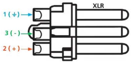

Note: Pin outs may vary, please refer to the audio device's manual to ensure a correct connection.
Important! When terminating cables, please ensure exposed adjacent wires do not touch. This may result in a short that can damage connected devices.
BALANCED UNBALANCED


Important! With unbalanced connections a jumper is needed between ground and negative to reduce noise
Microphone Connection
MIC (Dynamic MIC)
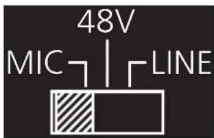
Connect dynamic or self-powered microphones in this mode.
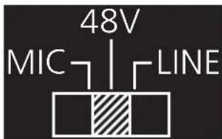
Use this setting for phantom powered microphones. Supplies 48 volts.
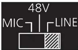
Connect wireless microphone receivers (or other sources) with line level outputs using this setting. Either balanced or unbalanced connections may be used.


Balanced Unbalanced
On Screen Display (OSD)
| Input Input 1 HDMI 1 | |||||
| Input 2 HDMI 2 | |||||
| Input 3 HDBaseT 1 | |||||
| Input 4 HDBaseT 2 | |||||
| Input 5 VGA 1 | |||||
| Component 1 | |||||
| Composite 1 | |||||
| S-Video 1 | |||||
| Input 6 VGA 2 | |||||
| Component 2 | |||||
| Composite 2 | |||||
| S-Video 2 | |||||
| Audio Volume Master -80 to +10db | |||||
| Sub HDMI 1 -80 to +10db | |||||
| HDMI 2 -80 to +10db | |||||
| HDBaseT 1 -80 to +10db | |||||
| HDBaseT 2 -80 to +10db | |||||
| Analog 1 -80 to +10db | |||||
| Analog 2 -80 to +10db | |||||
| Microphone -80 to +10db | |||||
| Line In -80 to 0db | |||||
| Bass -10 to 12 dB | |||||
| Treble -10 to 12 dB | |||||
| Video Contrast 0 to 100 | |||||
| Brightness | 0 to 100 | ||||
| Sharpness | 0 to 30 | ||||
| Color 0 to 100 | |||||
| Tint | 0 to 100 | ||||
| H Position | 0 to 40 | ||||
| Phase | 0 to 63 | ||||
| NR | BNR | Disabled | |||
| Low | |||||
| Medium | |||||
| High | |||||
| MNR | Disabled | ||||
| Low | |||||
| Medium | |||||
| High | |||||
| RNR | Disabled | ||||
| Low | |||||
| Medium | |||||
| High | |||||
| Scale | Full | ||||
| Overscan | |||||
| Underscan | |||||
| Letterbox | |||||
| Panscan | |||||
| Follow Input | |||||
| Setup Language English | |||||
| Spanish | |||||
| French | |||||
| German | |||||
| OSD Settings Transparency | |||||
| Position Horizontal | |||||
| Vertical | |||||
| Menu Timer 10 sec | |||||
| 30 sec | |||||
| 60 sec | |||||
| Logo On | |||||
| Off | |||||
| Info Banner On | |||||
| Off | |||||
| Output Format HD Pass Through | 480i@60 (NTSC)480p@60720p@601080i@601080p@60576i@50 (PAL)576p@50720p@501080i@501080p@501080p@24 | ||||
| Native | |||||
| UHD 3840x2160p@24 | 3840x2160p@253840x2160p@304096x2160p@244096x2160p@30 | ||||
| PC-1 640x480@60 | 640x480@72640x480@75800x600@60800x600@72800x600@751024x768@601024x768@721024x768@75 | ||||
| PC-2 1280x768@60 | 1280x800@601280x960@601280x1024@601360x768@601366x768@601400x1050@601440x900@601600x900@601600x1200@601920x1200@60 | ||||
| Network Network Status MAC | Address | xx-xx-xx-xx-xx-xxIP Addressxxx.xxx.x.xxxSubnetxxx.xxx.xxx.xGatewayxxx.xxx.x.x | |||
| DHCP ON | |||||
| OFF | |||||
Note: After selecting a new language, close the menu and reopen it for the change to take effect.
| Status System Info Software Revision | x.x.xx (e.g. 1.0.01) | |
| OSD Revision | x.x.x (e.g. 1.0.0) | |
| FPGA Revision | x.x.x (e.g. 1.0.0) | |
| On-Time (h-m) | x:xx (e.g. 1:15) | |
| Video Info Input | xxxx (e.g. HDMI 1) | |
| Signal Type | xxxx (e.g. HDMI) | |
| Video Format | xxxx (e.g. 1080i@60) | |
| Aspect | xxxx (e.g. 16x9) | |
| Color Space | xxxx (e.g. YUV) | |
| Color Depth | xxxx (e.g. 24) | |
| Audio Info Input | xxxx (e.g. HDMI 1) | |
| Audio Format | xxxx (e.g. PCM) | |
| Sampling Rate | xxxx (e.g. 48 KHz) | |
| Channels | xxxx (e.g. 2-Ch) |
TCP/IP
For convenience, the CLSO-612ED comes with DHCP on. This enables the switcher to be connected to a network without concern for overlapping IP addresses with other devices on the network. If your network does not support DHCP, this feature may be turned off and the IP address set using RS-232 commands or the WebGUI.
Note: If your system is controlled using IP, it is strongly recommended that you disable DHCP and select a unused IP address so that your system controller doesn't lose contact with the switcher.
TCP/IP WebGUI
Atlona has created an easy to use WebGUI for initial setup and later changes to the configuration of the CLSO-612ED.
To begin, connect the LAN port of the CLSO-612ED to your network. Type the IP address of the CLSO-612ED into the web browser of a PC connected to the same network (as seen below).
To find the switcher IP: Select "Network Status" within the OSD menu or use RS-232 command "IPCFG".

Important: If any stability issues are experienced, disable any anti-virus or firewall that may interfere with network communication to the switcher. Once set up is done and the switcher GUI is no longer being used, the firewall and anti-virus can be re-enabled.

AT-UHD-CLSO-612ED Login
Please input username and password.

A login screen will appear (this is the same log in for admin and general users). For the first log in (and future admin changes) the username is "root" and password is "Atlona".
Note: Only the admin password can be changed (see page 17). The username will always remain "root".

ATLONA
Connecting Technology
AT-UHD-CLSO-612ED

The home screen tab will display the general system information. If an HDMI or HDBaseT port is the current input, audio will display (see image above). If an analog port is selected then no audio information is displayed. (see below)

ATLONA
Connecting Technology
AT-UHD-CLSO-612ED
Home
Network Setup
Settings
Config
EDID
Audio
Control
HDVS
Update
System Info.
| Model: | AT-UHD-CLSO-612ED |
| Software Revision: | 1.0.01 |
| FPGA Revision: | 1.0.1 |
| OSD Revision: | 1.0.0 |
| On-Time(h-m): | 4:05 |
Video Info.
| Input: | VGA 1 |
| Signal Type: | -- |
| Video Format: | -- |
| Aspect: | -- |
| Color Space: | -- |
| Color Depth: | -- |

ATLONA
Connecting Technology
AT-UHD-CLSO-612ED Setup

The network set up page will allow the IP information to be changed. When a change is made the screen will grey and the ability to save or cancel will display at the bottom (see below).
Note: When DHCP is on, the IP address cannot be configured. Turn DHCP off to enable IP configuration.
Note: For a stable connection when using a control system, it is best to set up a static IP. When selecting an IP address, make certain no other devices on your network are using that IP address.
Note: Be sure to save all changes before moving to the next page.

Login Mode has been added to provide a secure telnet login. Once Login Mode has been turned on a username and password will be required on all IP connections to the switcher.
Note: Login mode should be in off position when the CLSO is used with control systems that do not support passwords. If your control system supports password protection, set the login mode to on.
The GUI always requires a password.
Note: The username and password used in IP Login Mode will be the same login information as the WebGUI.

ATLONA
Connecting Technology
AT-UHD-CLSO-612ED
Settings

The settings page is used to set front panel and video options. Select the source from the first menu. If VGA is selected, more video options will display. (see top of page 16)
System Settings
Power - Turn the switcher on and off
Panel Lock - Locks/unlocks the front panel buttons
Auto Switch - Turns auto switching between HDMI and HDBaseT inputs on/off
VGA auto switch - Turns VGA auto switching on/off
Note: VGA auto switching is only available on VGA and will not work with component, composite, and S-Video
*Component, composite, and S-Video poll settings will grey out when VGA auto switching is on*
Output Resolution
Switch between multiple video output resolutions:
Pass through - Input video will pass to the display without being scaled
Native - Upscales/downscales the output signal to match the HDBaseT display's preferred resolution
HD - Will upscale/downscale the output signal to match the selected HD resolution
PC - Will upscale/downscale the output signal to match the selected PC resolution
Note: When the output is set to UHD resolutions, UHD sources are passed through without scaling. Frame rates are not changed. (e.g. if 3840x2160@30Hz input is received, output will remain 30Hz even if output is set to 24Hz)
Video Settings
| Scale | Follow Input |
| BNR | Medium |
| MNR | Medium |
| RNR | Medium |
Poll Settings
| VGA 1Component 1Composite 1S-Video 1 | VGA 2Component 2Composite 2S-Video 2 |
OSD Display Setting
| OSD func. | ON |
| OSD info. | ON |
HDMI
HDBaseT
Video Settings

VGA/Component/Composite/S-Video
Factory Default
Video Settings
Set the output video settings:
Scale - Sets video output aspect ratio - Full, overscan, letter box, pan and scan, or follow input
Full - Sources always fill the screen, regardless of source aspect ratio
Overscan - Image is slightly zoomed in so that broadcast data at edges is masked
LetterBox - Used to create 16:9 aspect ratio on 4:3 aspect ratio TVs
Pan and Scan - Used to create 4:3 aspect ratio on 16:9 aspect ratio TVs
Follow Input - Aspect ratio on TV matches source aspect ratio
BNR - Block noise reduction - Disabled, low, medium, or high
MNR - Mosquito noise reduction - Disabled, low, medium, or high
RNR - Random noise reduction - Disabled, low, medium, or high
Contrast* - Sets output white levels - 0 up to 100
Brightness* - Sets output black levels - 0 up to 100
Sharpness* - Sets output sharpness - 0 up to 30
Color* - Sets output color saturation - 0 up to 100
Tint* - Sets output hues - 0 up to 100
H Position* - Sets the horizontal position of the output video
Phase* - Adjusts digital sample timing to minimize image noise
*Only available when inputs 5 and 6 (VGA 1 & VGA 2) are selected

Poll Settings
Turn analog input options on and off. If a selection is unchecked it will not display as an input option when switching to input 5 or 6.
e.g. In the above picture, only VGA and S-Video would show as a source option
Note: Component, composite, and S-Video poll settings will grey out when VGA auto switching is on

OSD Display Settings
OSD func - Turns the CLSO's display OSD menu on/off
OSD info - Turns the source information on the display on/off when switching
Factory Default
It will reset parameters.
Confirm Cancel
Factory Default
Select to reset CLSO back to factory settings.
Note: This will reset the switcher to factory default, including resolutions, audio settings, HDCP settings, etc.

ATLONA
Connecting Technology
AT-UHD-CLSO-612ED
Config

The config page will allow the admin password to be changed, users to be added, and the RS-232 ports to be configured (both CLSO-612ED system ports and the RS-232 I/O ports accessed through the analog RS-232 interfaces and HDBaseT connections.
Note: User information will display for the admin only.
Note: Only the admin password can be changed. The admin username will always remain "root". If the admin password is lost the system must be returned to factory settings and setup repeated.

ATLONA
Connecting Technology
AT-UHD-CLSO-612ED EDID
| Home | Network Setup | Settings | Config | EDID | Audio | Control | HDVS | Update |
| Prefer Timing(HDMI): | Default | |||||||
| Prefer Timing(VGA): | Default | |||||||
| Input1 HDCP: | Compliant | |||||||
| Input2 HDCP: | Compliant | |||||||
| Input3 HDCP: | Compliant | |||||||
| Input4 HDCP: | Compliant |
The EDID page enables the input preferred timing to be selected and HDCP compliance reporting to be set. This function is controllable through RS-232 as well.
Note: CLSO-612ED protects HDCP encoded content and will not pass HDCP content to a non-HDCP compliant device.
Note: Some devices flag all content as protected when connected to an HDCP compliant display. This prevents what should be non-protected content from reaching devices (i.e. teleconference system) through the CLSO-612ED.
Note: When HDCP reporting is non-compliant, only user created content is transmitted. Protected content from all sources (e.g. BluRay, AppleTV, etc) is blocked.

ATLONA
Connecting Technology
AT-UHD-CLSO-612ED Audio

Audio settings adjust output volume for all sources including the microphone.
Master - Affects all sources at the same time
Inputs - Used to balance levels from each source.
Note: For best results, gains should be balanced between master and source levels.
Ducking Settings
| Microphone | ON | |
| Attack Time | 400 ms | |
| Release Time | 1500 ms | |
| Trig Level | -35 dB | |
| Program Decrease | 30 dB | |
Microphone ducking uses the audio level from the microphone to decrease the program level so the speaker may be heard.
Note: Proper set up is critical for satisfactory operation. If program levels are too high they can trigger the ducking process.
Note: Setting the microphone volume too high may result in feedback.
It is recommended that a handheld or headset microphone be used with ducking to reduce feedback and maximize the difference between voice and program levels.
Best results are received with the following sequence:
- Set master volume to 0. (This is 10 db below maximum)
- Raise appropriate microphone (or line in) volume until just below feedback or adequate volume is reached (whichever setting is lower). - Master level and amplifier gains may be increased to get appropriate levels
Note: If feedback occurs and volume is not adequate, move the speakers and/or microphone to eliminate feedback.
-
Raise source "sub" volumes to appropriate levels without talking
-
Set attack time to minimize popping, but still fast enough that initial talking sounds are heard.
-
Set release time so that program levels do not increase between sentences.
Note: Shorten time so that the microphone doesn't interfere with the program.
- Set the trigger level so that words spoken at a normal level trigger the ducking process
Note: Set the trigger level too sensitive and the program will trigger the ducking. Set too low and the speaker will have to talk very loudly to trigger ducking. The further right the slider is, the more sensitive the setting.
- Set program decrease to ensure when ducking is triggered the program level is low enough the speaker can be heard.
Fine tuning these settings will help achieve the best results.

ATLONA.
Connecting Technology
AT-UHD-CLSO-612ED
Control



The Control Page includes settings which enable display controls by the switcher. It provides a way to program button functions, turn auto switching on/off, and determine the type of control commands (TCP/IP or RS-232) sent out.
Button Control Selection
Power - Set which device the power button controls
None: Power button will turn the UHD-CLSO-601 on and off
RS-232: Power button will send power on/off command over HDBaseT using RS-232 to compatible receivers and displays
IP: Power button will send power on/off command over Ethernet using either the LAN connection or the HDBaseT connection
CEC: Sends CEC command over HDBaseT to the HDMI output of the receiver Volume/Mute
Audio Out: Volume and mute buttons will control volume output of the switcher
RS-232: Volume/Mute buttons will send the commands over HDBaseT or RS-232 zone 7, using RS-232 to compatible receivers and displays
IP: Volume/Mute buttons will send the commands over Ethernet using either the LAN connection or the HDBaseT connection
Display Mode - Sets functionality of the power button
DispSW AVon: Display switches on/off, source audio/video signal always on
DispSW AVSW: Display switches on/off, source audio/video signal switches on/off
AV SW: Display is always on, source audio/video signal switches on/off
Always ON: No function
Note: Must be in DispSW AVon or DispSW AVSW for RS-232 display control to work
CEC Control
Power
On - Sends a command over HDBaseT to the HDMI output of the connected receiver to turn the connected display on
Off - Sends a command over HDBaseT to the HDMI output of the connected receiver to turn the connected display off
Note: CEC may not work with every display type. See notice at the bottom of page 3 for more information.
| System Settings | ||
| Display Auto Power On | Enabled | Disabled |
| Display Auto Power Off | Enabled | Disabled |
| Power Button Lock | Enabled | Disabled |
| Lamp Cool Down Timer (0~300) | 0 Sec | Save |
| Auto Power Off Timer (1~240) | 10 Sec | Save |
| Display Warm Up Timer (0~300) | 0 Sec | Save |
| Control Type | RS-232 | |
| Feedback Verify | ON | |
| Display Mode | DispSW AVon | |
System Settings
Display Auto Power On - When enabled, the unit will send a programmed command to the display to turn on after detecting an A/V signal
Display Auto Power Off - When enabled, the unit will send a command to the display to turn off after not detecting an A/V signal
Lamp Cool Down Timer (0-300) - Used with a projector whose lamp cannot be turned on for up to 5 minutes after being shut off. Match settings with lamp delay on projector
Auto Power Off Timer (1-240) - Sets the period of time between the loss of A/V signal and when the "Display Off" command is sent
Note: LED will blink red for the auto power off time period then go solid
Note: All functionality remains, only the HDBaseT output is turned off
Display Warm Up Timer (0-300) - Sets the period of time after the display is turned on, that the power button will be locked
Note: LED will blink green for the warm up timer period and then stay solid
Note: When timers are set to 0 seconds, they will disable the timers' functions
Control Type - Select whether the display on/off commands are sent using RS-232, TCP/IP, or CEC
Feedback Verify
On: If receiving no feedback, the product will send the command up to 4 times
Off: The command will only be sent once, whether feedback is received or not Display Mode -
DispSW AVon: Display switches on/off, source audio/video signal always on
DispSW AVSW: Display switches on/off, source audio/video signal switches on/off
AV SW: Display is always on, source audio/video signal switches on/off
Note: Must be in DispSW AVon or DispSW AVSW for RS-232 display control to work


TCP/IP Settings of Controlled Device
This option sets the IP for display control. The static IP set here should match the display's static IP. To set or view the display's IP address, check the display's user manual.
Note: The switcher and the display must be on the same network for these commands to work Note: Be sure the static IP address set for the display does not match any other device on the network
IP Mode Non-login: Does not require a username and password when using TCP/IP to control the display
Login: Requires a username and password to control the display through TCP/IP IP Address & Port - Set to match the display's static IP Username & Password - Required when in login mode Save - Saves the IP settings for accessing the controlled device
RS-232/IP Commands
ASCII/Hex - Set which type of commands are sent to the display On/Off/Volume+/Volume-/Mute - Enter the specific commands and feedback that will be sent/received when using any of the control options Note: Individual commands will be found in the display's manual End of line symbols - None, CR, LF, CR-LF, Space, STX, ETX, Null - Select the appropriate symbol from the drop down list. Carriage return, line feed, and carriage return with line feed are the most commonly used symbols. Note: Be sure to check the display's manual for the correct symbol
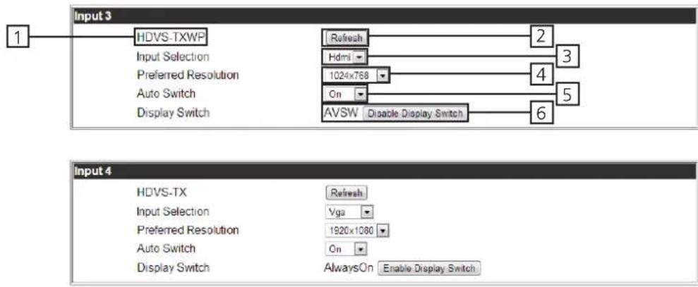
- Displays model number of connected HDVS transmitter
- Refresh button - Ensures the correct and current settings are displayed
- Input selection - Switch between the HDVS inputs
- Preferred resolution - Sets the HDVS VGA port preferred input resolution
- Auto switch - Turns auto switching on/off for the HDVS transmitter
- Display switch - Sets display switch function of the HDVS (default is disabled) Recommended set to disabled - product will be always on

ATLONA
Connecting Technology
AT-UHD-CLSO-612ED
Update
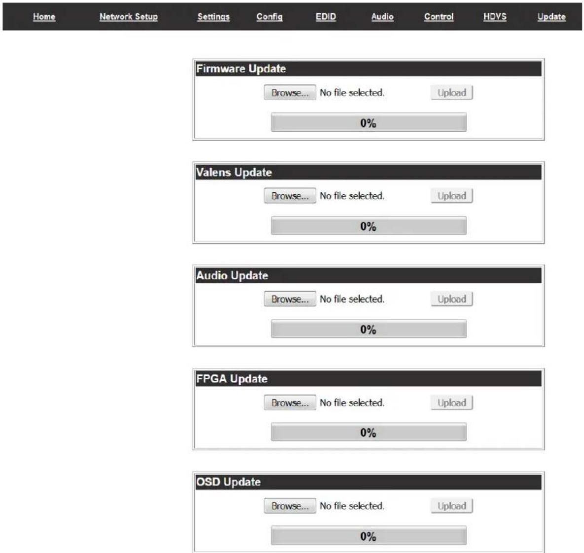
The firmware page provides an area to update the switcher, Valens (HDBaseT), audio, FPGA, and OSD firmwares.
- Select the browse button for the type of firmware to be updated
- Firmware Update - MCU/Main firmware
- Valens Update - Valens firmware
- Audio Update - DSP firmware
- FPGA Update - FPGA firmware
- OSD Update - OSD firmware
- Select the new firmware file that was downloaded either from atlona.com or box.com
- Press the update button
A progress bar will display as the update is completed. After the update is complete, if a restart is required, the webGUI will display a prompt. The firmware update is now complete and the switcher is ready to be used.
Note: Current firmware can be found at http://www.atlona.com/product/AT-UHD-CLSO-612ED/ under the firmware tab.
IR
System IR is typically used to connect to control system processors. The signal is routed through the System IR IN and repeated to out all the IR OUT ports, including the HDBaseT ports. This input may also be used to control the CLSO-612ED.
Note: HDBaseT ports must be connected to HDBaseT receivers and transmitters with IR capabilities.
(e.g. AT-HDTX-IR, AT-HDTX-WP, AT-HDWP-IR, AT-HDRX-IR, etc)

For your convenience the cables do not come pre-terminated. Each item, whether it's an IR receiver or IR emitter, will have wires exposed. Each wire is encased in a different colored cover. A female IR captive screw connector has been included (see picture 1).
IR pin outs have been included for the included IR emitter and IR receiver (see picture 2 & 3). The wires are colored for each pin (see picture 4 and 5).
Remote
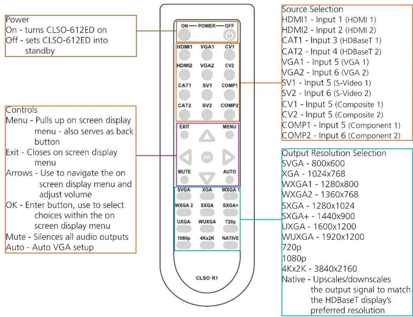
RS-232
Connection
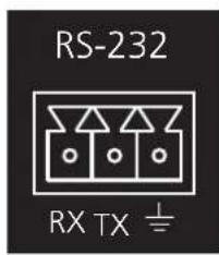
RS-232 pin out will be determined by the RS-232 cable and will connect as Rx (receiver), Tx (transmitter), and ± (ground). (See picture 1)

natural_image
Close-up of a green terminal block with three red, blue, and black wires attached (no text or symbols visible)Wire color will differ by cable manufacturer.
RS-232 is often connected through a 9-pin D to captive screw connector. The pins will have functions associated with them, some will be unassigned.
Note: Typical DB9 connectors use pin 2 for TX, pin 3 for RX, and pin 5 for ground. On some devices functions of pins 2 and 3 are reversed.

Set Up
To set up the RS-232 hyperterminal (if not using 3rd party software) use the following steps:
- Connect the CLSO-612ED to a PC using a 3 pin to USB cable
- Go to the Device manager folder (see picture A)
- Find the CLSO-612ED COM port and right click with a mouse and select properties (see picture B)
Note: If unsure which COM port is the CLSO-612ED, unplug the cable and plug it back in. It will disappear and reappear on the COM port list.
- Under the properties menu select the port settings tab and update the menu to the CLSO-612ED default settings of: Bits Per Second: 115200, Data Bits: 8, Parity: None, Stop Bits: 1 and Flow Control: None. (see picture C)
Set up is done and any hyperterminal program may be used to control the CLSO-612ED now.

Commands
The command codes are case sensitive, do not change capitalization, spacing, or lettering.
| Command Feedback | Description | |
| PWONPWON Power ON | ||
| PWOFFPWOFF Stand-by | ||
| PWSTA PWON/PWOFF Get system power status | ||
| RS232zone[X][Y] RS232zoneX[Y] RS232zoneX[Y], X: 1-8. Y is the command sent to the HDBT [Y] is the command string sent to the display device | ||
| RS232para[X][Y] RS232paraX[Y] RS232paraX[baudrate,databit,parity,stopbit] X is 1-8. [Y] is the parameter for RS232. | ||
| CSpara[Y] CSpara[Y] Set RS232 parameter [Y] is the parameter for RS-232. | ||
| VOL+ VOL(xx) Turns the volume up one level | ||
| VOL- | VOL(xx) Turns the volume down one level | |
| VOL(xx) | VOL(xx)e.g. VOL(10) | Turns volume to the specified level <xx: 10 ~ -80>Read the volume current level status => VOLe.g. Adjusts the master volume level to -23dB => VOL(-23) |
| MVOL+ | MVOL(xx) | Turns the MIC volume up one level |
| MVOL- | MVOL(xx) | Turns the MIC volume down one level |
| MVOL(xx) | MVOL(xx)ex. MVOL(30) | Turns MIC5V volume to the specified level <xx: 30 ~ -80>Read the MIC5V volume current level status => MVOL |
| MICx [Y] | MICx [Y]e.g. MICON 20 | Sets up MIC valuesx = on / off / sta / atime (attack time) / rtime (background release time) / sens (microphone sensitivity level) / reduce (background reduce level) [Y] = value (e.g. 20) |
| LVOL+ LVOL(xx) | Turns the Line volume up one level | |
| LVOL- | LVOL(xx) | Turns the Line volume down one level |
| LVOL(xx) | LVOL(xx)e.g. LVOL(0) | Turns Line volume to the specified level <xx: 0 ~ -80>Read the Line volume current level status => LVOL |
| SnVOL+ | SnVOL(xx) | Turns the Sub volume up one level <n: 1-6> (n = input number)e.g. Adjusts the HDBT2 volume to up => S4VOL+ |
| SnVOL- | SnVOL(xx) | Turns the Sub volume down one level <n: 1-6> (n = input number)e.g. Adjusts the VGA1 volume to down => S5VOL- |
| SnVOL(xx)e.g. S2VOL(-15) | SnVOL(xx)e.g. S2VOL(-15) | Turns Sub volume to the specified level <n: 1-6, xx: 0 ~ -80>(n = input number)Read the Sub volume current level status => SnVOLe.g. Adjusts the HDMI1 volume level to -10dB => S1VOL(-10) |
| VOLMute [Y] | VOLMute [Y] | VOLMute [on/off/sta]. Set volume to mute on. => VOLMute on |
| Menu[X] | Menu[X]e.g. MenuDown | Sets to control OSD interface, [X]: Sw/Up/Down/Left/Right/Info/SeIe.g. Select OSD option => MenuSel |
| Lock | Lock Locks the front panel | |
| Unlock | Unlock | Unlocks the front panel |
| Version [Y]e.g. Version osd | Version [Y]e.g. Version x.x.xx | Brings up the software versions: ex. Version mcufirmware [mcu]OSD menu [osd]DSP [dsp]FPGA [fpga] |
| Type | AT-UHD-CLSO-612 | Brings up the model information |
| Mreset | Mreset | Reset device to manufacture default |
| EQB+ EQB(xx) Turns EQ bass up one level | ||
| EQB- EQB(xx) Turns EQ bass down one level | ||
| EQB(xx) EQB(xx) Turns EQ bass to the specific level xx: (xx: -10 to 12) | ||
| EQT+ EQT(xx) Turns EQ treble up one level | ||
| EQT- EQT(xx) Turns EQ treble down one level | ||
| EQT(xx) EQT(xx) Turns EQ treble to the specific level xx: (xx: -10 to 12) | ||
| ManHPos+ ManHPos(xx) Sets horizontal position one pixel to the right | ||
| ManHPos- ManHPos(xx) Sets horizontal position one pixel to the left | ||
| ManHPos(xx) ManHPos(xx) Sets horizontal position to a specific setting (xx: 0-40) | ||
| ManPha+ ManPha(xx) Adjusts pixel phase up one level | ||
| ManPha- | ManPha(xx) Adjusts pixel phase down one level | |
| ManPha(xx) | ManPha(xx) Adjusts pixel phase to a set amount (xx: 0 to 63) | |
| VFmtRes [Y]e.g. VFmtRes 09 | VFmtRes XXe.g. VFmtRes 09 | Set output video format to any of the [Y] resolutions belowe.g. Set output video format to 1080p@60 => VFmtRes 06e.g. Read the list of video format => VFmtRes List |
[Y] resolution list -
| 00 | Pass-Through | 01 | 640x480p60 | 02 | 720x480i60 |
| 03 | 720x480p60 | 04 | 1280x720p60 | 05 | 1920x1080i60 |
| 06 | 1920x1080p60 | 07 | 720x576i50 | 08 | 720x576p50 |
| 09 | 1280x720p50, | 10 | 1920x1080i50 | 11 | 1920x1080p50 |
| 12 | 1920x1080p24 | 13 | 1920x1080p25 | 14 | 1920x1080p30 |
| 15 | 640x480p72 | 16 | 640x480p75 | 17 | 800x600p60 |
| 18 | 800x600p72 | 19 | 800x600p75 | 20 | 1024x768p60 |
| 21 | 1024x768p72 | 22 | 1024x768p75 | 23 | 1280x768p60 |
| 24 | 1280x800p60 | 25 | 1280x960p60 | 26 | 1280x1024p60 |
| 27 | 1360x768p60 | 28 | 1366x768p60 | 29 | 1440x900p60 |
| 30 | 1600x1200p60 | 31 | 1920x1200p60 | 32 | 2048x1080p24 |
| 33 | 2048x1080p50 | 34 | 2048x1080p60 | 35 | 2048x1152p60 |
| 36 | 3840x2160p24 | 37 | 3840x2160p25 | 38 | 3840x2160p30 |
| 39 | 4096x2160p24 | 40 | 4096x2160p30 | 41 | 1400x1050p60 |
| 42 | 1600x900p60 | 43 | 2560x1600p60 | 254 | Native |
| SetCmd X[Y]e.g. SetCmd on[PWR ON] | SetCmd X[Y]e.g. SetCmd on[PWR ON] | Sets the RS-232 or IP command for the selected button or function X= on, off, vol+, vol-, and mute Y= commande.g. Set the on command to send the command PWR ON |
| SetEnd X[Y]e.g. SetEnd off[CR-LF] | SetEnd X[Y]e.g. SetEnd off[CR-LF] | Sets the line termination for the chosen command X= on, off, vol+, vol-, mute, fbkon, fbkoff, fbkmute Y= None, CR, LF, CR-LF, Space, STX, ETX, and nulle.g. Set the command off to have a carriage return and line feed |
| SetFbVerify Xe.g. SetFbVerify on | SetFbVerify Xe.g. SetFbVerify on | Verifies the device is receiving commands X= on, off, stae.g. Sends command up to 4 times until feedback verifies command was received with feedback |
| TrigCEC Xe.g. TrigCEC on | TrigCEC Xe.g. TrigCEC on | Triggers the stored CEC command to turn the display on and off X= on, off |
| TrigRS Xe.g. TrigRS vol+ | TrigRS Xe.g. TrigRS vol+ | Triggers the RS-232 command from RS-232 or IP X= on, off, vol+, vol-, and mute |
| TrigIP Xe.g. TrigIP vol- | TrigIP Xe.g. TrigIP vol- | Triggers the IP command from RS-232 or IP X= on, off, vol+, vol-, and mute |
| CtlType Xe.g. CtIType rs-232 | CtlType Xe.g. CtIType rs-232 | Sets the control type X= ip, rs-232, cece.g. Set the control type to RS-232 |
| CliMode Xe.g. CliMode non-login | CliMode Xe.g. CliMode non-login | Sets the control device's IP mode X= sta, login, non-login e.g. Sets the IP mode to non-login |
| CliUser Xe.g. CliUser | CliUser Xe.g. CliUser admin | Sets the IP username for login X= username, (blank)e.g. Display the IP username by leaving x blank |
| CliPass Xe.g. CliPass AtlonA | CliPass Xe.g. CliPass AtlonA | Sets the IP password for login X= password, (blank)e.g. Set the IP password to AtlonA |
| CliIPAddr Xe.g. CliIPAddr sta | CliIPAddr Xe.g. CliIPAddr 192.168.0.23 | Sets the IP address of the controlled device X= ip, stae.g. Display the IP address of the controlled device |
| CliPort Xe.g. CliPort 24 | CliPort Xe.g. CliPort 24 | Sets the IP port of the controlled device X= port, stae.g. Set the IP port to 24 |
| AutoDispOff X AutoDispOff X | Enable or disable display auto off X= on, off, sta | |
| AutoDispOn X AutoDispOn X | Enable or disable display auto on X= on, off, sta | |
| APwrOffTime X APwrOffTime | X Sets how long after receiving no signal to trigger auto display off X= 1-240, sta | |
| ProjSWMode X | ProjSWMode X | Set delay time for the display on command to be sent X= 0-300, staNote: Match the timing to the projector's delay settings |
| ProjWarmUpT X ProjWarmUp | T X Set period of time after the display is turned on that the power command will not send X= 0-300, sta | |
| VolKeyOPT X VolKeyOPT X Set | Set the control type/device the volume button sends out X= 0-2 | |
| DispRS X DispRS X Sets the display command type to RS-232 X= on, off, sta | ||
| DispCEC X DispCEC X Sets the display command type to CEC X= on, off, sta | ||
| DispIP X DispIP X Sets the display command type to TCP/IP X= on, off, sta | ||
Each command is terminated with a carriage return.
Feedback is terminated with a carriage return and line feed.
Note: If the command fails or is incorrect the feedback should be "Command FAILED"
Volume Key
| 0 HDVS | 1 RS-232 | 2 IP | |
| Display Key | |||
| 0 HDVS | 1 RS-232 | 2 CEC | 3 IP |
| Command Feedback | Description | |
| Input [X] [Y] Input [X] | [Y]Input HDBT 2 | Input [interface]* [index]*. Select input source video.e.g. Select input to HDBT 2 video => Input HDBT 2 |
| HDCPSetX [Y]ex. HDCPSet2 off | HDCPSetX Yex. HDCPSet2 off | Sets HDCP mode of the HDMI ports X = 1/2/3/4 Y = on/off/sta |
| PrefTimg [X] PrefTimg | [X] Set preferred timing | to EDID. X is 1-10 & sta |
| VGAPrefT [X] VGAPrefT | [X] Set preferred VGA | timing to EDID. X is 1-8 & sta |
| BNR [Y] BNR [Y] BNR | [off/low/medium/high/sta].Configure video block noise reduction | |
| MNR [Y] MNR [Y] MNR | [off/low/medium/high/sta].Configure video mosquito noise reduction | |
| RNR [Y] RNR [Y] RNR | [off/low/medium/high/sta].Configure video random noise reduction | |
| PollAddInX [Y] PollAddInX | [Y] PollAddInX [VGA | /COMP/CV/SV]. Add source of analog polling. X = 1(VGA input 5) or 2 (VGA input 6). Ex: PollAddIn2 SV allows enablingof SV for VGA input 5. |
| PollDelInX [Y] PollDelIn | [Y] PollDelInX [VGA/CO | MP/CV/SV]. Delete source of analog polling. X =1 (VGA input 5) or 2 (VGA input 6). Ex: PollDelIn VGA,CV,COMP willdelete VGA & CV & COMP |
| OSD [Y] OSD [func/logo/info][on/off/sta] | ||
| Aspect [Y] Aspect [Y] Aspect [full/overscan/underscan/letterbox/panscan/follow/sta] | ||
| OutAMute [Y] | OutAMute [Y] OutAMute [on/off/sta]Sets output audio mute of HDMI and HDBT | |
| AUD In[X] Ai[Y] | AUD In[X] Ai[Y] | AUD In[X] Ai[Y] x: 1-6 Y: 5-6 or PReplaces the selected input's audio with the selected analog input (5or 6) or sets it to pass through (p) normallye.g. Replace input 2's audio with analog 6 - Aud In2 Ai6e.g. Pass through input 3's audio normally - Aud In3 AiP |
| AutoSW [Y] | AutoSW [Y] | AutoSW [on/off/sta/VGAon/VGAoff/VGAsta]Sets auto switch mode statusFactory Default: Sets auto switch to on with VGA auto switch to off |
| ASwPrePort [Y] | ASwPrePort [Y] | ASwPrePort [HDMI1/HDMI2/HDBT1/HDBT2/Previous]Sets default auto switch port or sets to previous input |
| ASwOutTime [Y] | ASwOutTime [Y] | ASwOutTime [sec] Sec: 1-600 (default is 1 second)Sets the delay time for how long the auto switching receives no signalfrom the input before switching portse.g. Sets the auto switching delay time to 1 minute with no signal beforechanging ports - ASwOutTime60 |
[Interface] index -
| HDMI 1 | HDMI 2 | HDBT 1 |
| HDBT 2 | COMP 1 | COMP 2 |
| CVBS 1 | CVBS 2 | SVIDEO 1 |
| SVIDEO 2 | VGA 1 | VGA 2 |
[X] preferred timing -
| 1 | 1280x800 | 2 | 1920x1080 | 3 | 1024x768 |
| 4 | 1280x720 | 5 | 1920x1200 | 6 | 1366x768 |
| 7 | 800x600 | 8 | 1600x900 | 9 | 2560x440 |
| 10 | 3840x2160 | sta | Read status |
VGA [X] preferred timing -
| 1 | 1280x800 | 2 | 1920x1080 | 3 | 1024x768 |
| 4 | 1280x720 | 5 | 1920x1200 | 6 | 1366x768 |
| 7 | 800x600 | 8 | 1600x900 | sta | Read status |
IP Commands
| Command Feedback | Description | |
| IPCFG IP Addr : x.x.x | xNetmask : x.x.x.xGateway : x.x.x.xIP Port : x | Displays IP address configure |
| IPQuit IPQuit Telnet Logout | ||
| IPAddUser [X] [Y] IPAddUser [X] [Y] IPAddUser [name] [password]. Add user of telnet.If only command write “IPAddUser”, it will display all user list.=> IPAddUser | ||
| IPDelUser [Y] IPDelUser [Y] IPDelUser [name]. Del user of telnet | ||
| IPDHCP [Y] IPDHCP [Y] IPDHCP [on/off/sta]. Set: DHCP mode status and auto reset telnet.e.g. Set DHCP mode is on => IPDHCP on | ||
| IPStatic [X] [Y] [Z] IPStatic [X] [Y] [Z] IPStatic [Ad dress] [Netmask] [Gateway]. Set static IP address andauto reset telnet.e.g. Set static IP address is 192.168.1.1 255.255.255.0 192.168.1.254=> IPStatic 192.168.1.1 255.255.255.0 192.168.1.254 | ||
| IPPort [Y] IPPort [Y] IPPort [port]. Set telnet port and auto reset telnete.g. Set telnet port 80 => IPPort 80 | ||
| IPLogin [Y] IPLogin [Y] IPLogin [on/off/sta]. Set telnet login status.e.g. Set telnet login is on => IPLogin on | ||
| Broadcast [Y] Broadcast [Y] Broadcast [on/off/sta]. Broadcast switch.e.g. Set broadcast mode is on => Broadcast on | ||
| IPTimeout [Y] | IPTimeout [Y] | IPTimeout [Sec]. Set telnet idle timeout time. Default is 2 minute.e.g. Set telnet idle timeout 10 minutes => IPTimeout 600 |
Each command must be terminated with a carriage return and line feed.
Feedback is terminated with a carriage return and line feed.
Note: If the command fails or is incorrect the feedback should be "Command FAILED"
Baud Rate
Zone RS-232 port configuration must match the connected device on all parameters including baud rate, data-length, parity, and stop-bit. These parameters can easily be set using the WebGUI or following commands through RS-232 or TCP/IP.
The baud rate for the switcher is for switcher control and the transmitter/receiver baud rate is for control of the RS-232 device in zone. All commands from your control processor are at the settings for the switcher. The switcher will modify the baud rate and other settings to these set parameters by zone.
Note: Baud rate options 2400, 4800, 9600, 19200, 38400, 57600, or 115200
Command for Switcher Parameters
CSpara[baudrate, data-length, parity, stop-bit] (data, parity, and stop bit for switcher must be 8,0,1)
For example if you wish to change the baud rate of the switcher to 38400 the command would look like this:
CSpara[38400,8,0,1]
Note: Default for the switcher is: Baud rate-115200bps, Data length-8bit, Parity-None, Stop Bit-1
RS-232 Command for the Output baud rate status
RS232para
The RS-232 status command will provide feedback for the current parameters for each transmitter/receiver. There are eight RS-232 zones:
RS-232 zone 1 and 2 are dedicated to the HDMI Inputs 1 and 2
RS-232 zone 3 and 4 are HDBaseT Inputs 3 and 4
RS-232 zone 5 and 6 are dedicated to RG15 inputs 5 and 6
RS-232 zone 7 is dedicated to HDMI Output
RS-232 zone 8 is HDBaseT Output
Example: (See example of feedback below)
RS232para
Current RS232 parameter:
- Zone 1 :BaudRate 2400bps, DataBits 0, Parity None, StopBits 1.
- Zone 2 :BaudRate 9600bps, DataBits 0, Parity ODD, StopBits 1.
- Zone 3 :BaudRate 9600bps, DataBits 0, Parity None, StopBits 1.
Note: Zone 3 is HDBaseT 1, zone 4 is HDBaseT 2, and zone 8 is HDBaseT output.
Note: Default for the transmitters/receivers is: Baud-9600bps, Data length-8bit, Parity-None, Stop Bit-1
Control Diagram

flowchart
graph TD
    A["ATLONA"] -->|ATLON1: Ethernet port| B["Laptop"]
    C["Control System Processor"] -->|HDBaseT: Ethernet port| D["ATLON1: Ethernet port"]
    E["Video"] --> F["ATLON1: Ethernet port"]
    G["HDBaseT"] --> H["ATLON1: Ethernet port"]
    I["Control"] --> J["ATLON1: Ethernet port"]
    K["ATLON1: Ethernet port"] --> L["ATLON1: Ethernet port"]
    M["ATLON1: Ethernet port"] --> N["ATLON1: Ethernet port"]
    O["ATLON1: Ethernet port"] --> P["ATLON1: Ethernet port"]
    Q["ATLON1: Ethernet port"] --> R["ATLON1: Ethernet port"]
    S["ATLON1: Ethernet port"] --> T["ATLON1: Ethernet port"]
    U["ATLON1: Ethernet port"] --> V["ATLON1: Ethernet port"]
    W["ATLON1: Ethernet port"] --> X["ATLON1: Ethernet port"]
Use RS-232 commands to select inputs on AT-HDVS-TX
Connection and Installation

flowchart
graph TD
    A["Apple TV"] -->|or| B["ATLONA"]
    A -->|or| C["Laptop"]
    B --> D["ATLONA TX"]
    B --> E["Laptop"]
    C --> F["ATLONA"]
    C --> G["Laptop"]
    D --> H["ATLONA RX"]
    D --> I["Laptop"]
    E --> J["ATLONA RX"]
    E --> K["Laptop"]
    F --> L["ATLONA RX"]
    F --> M["Laptop"]
    G --> N["ATLONA RX"]
    G --> O["Laptop"]
    H --> P["HDMI"]
    H --> Q["VGA"]
    H --> R["HDBaseT"]
    H --> S["Audio"]
    H --> T["MIC"]
    I --> U["HDBaseT"]
    I --> V["Audio"]
    I --> W["MIC"]

flowchart
graph TD
    A["ATLONA"] -->|or| B["HDWR"]
    A -->|or| C["ICloud R"]
    A -->|or| D["ICloud N"]
    A -->|or| E["ICloud U"]
    A -->|or| F["ICloud V"]
    A -->|or| G["ICloud W"]
    A -->|or| H["ICloud X"]
    A -->|or| I["ICloud Y"]
    A -->|or| J["ICloud Z"]
    A -->|or| K["ICloud AA"]
    A -->|or| L["ICloud AB"]
    A -->|or| M["ICloud AC"]
    A -->|or| N["ICloud AD"]
    A -->|or| O["ICloud AE"]
    A -->|or| P["ICloud AF"]
    A -->|or| Q["ICloud AG"]
    A -->|or| R["ICloud AH"]
    A -->|or| S["ICloud AI"]
    A -->|or| T["ICloud AJ"]
    A -->|or| U["ICloud AK"]
    A -->|or| V["ICloud AL"]
    A -->|or| W["ICloud AM"]
    A -->|or| X["ICloud AN"]
    A -->|or| Y["ICloud AO"]
    A -->|or| Z["ICloud AP"]
    A -->|or| AA["ICloud AQ"]
    A -->|or| AB["ICloud AR"]
    A -->|or| AC["ICloud AS"]
    A -->|or| AD["ICloud AT"]
    A -->|or| AE["ICloud AU"]
    A -->|or| AF["ICloud AV"]
    A -->|or| AG["ICloud AW"]
    A -->|or| AH["ICloud AX"]
    A -->|or| AI["ICloud AZ"]
    A -->|or| AJ["ICloud BA"]
    A -->|or| AK["ICloud BB"]
    A -->|or| AL["ICloud BC"]
    A -->|or| AM["ICloud AD"]
    A -->|or| AN["ICloud AE"]
    A -->|or| AO["ICloud AF"]
    A -->|or| AP["ICloud AG"]
    A -->|or| AQ["ICloud AH"]
    A -->|or| AR["ICloud AI"]
    A -->|or| AS["ICloud AJ"]
    A -->|or| AT["ICloud AK"]
    A -->|or| AU["ICloud AL"]
    A -->|or| AV["ICloud AM"]
    A -->|or| AW["ICloud AU"]
    A -->|or| AX["ICloud AV"]
    A -->|or| AZ["ICloud AL"]
    A -->|or| BA["ICloud AM"]
    A -->|or| BB["ICloud AT"]
    A -->|or| BC["ICloud AU"]
    A -->|or| BD["ICloud AV"]
    A -->|or| BE["ICloud AL"]
    A -->|or| BF["ICloud AK"]
    A -->|or| BG["ICloud AL"]
Control Drivers
Visit the Control Drivers tab at http://www.atlona.com/AT-UHD-CLSO-612ED.html to download the control drivers for the CLSO-612ED.
CLSO-612 Updating
Visit the Firmware Update tab at http://www.atlona.com/AT-UHD-CLSO-612ED.html to download the current updates for the CLSO-612ED.
Note: Atlona is constantly improving and updating features and stability. It is recommended that you check to make sure you are on the most current firmware before installation, especially when using a control system.
Specifications
Video Resolutions
| IN | 4096x2160@24/25/30, 3840x2160@24/25/30 (UHD), 2048x1080p,1080p@23.98/24/25/29.97/30/50/59.94/60Hz, 1080i@50/59.94/60Hz, 720p@50/59.94/6 | |||
| 576p, | 576i, | 480p, | 480i | |
| 2560x2048, 2560x1600, 2048x1536, 1920x1200, 1680x1050, 1600x1200, 1600x900,1440x900, 1400x1050, 1366x768, 1360x768, 1280x1024, 1280x800, 1280x768, 1152x768,1024x768, | 800x600, | 640x480 | ||
| OUT | 4096x2160@24/25/30, 3840x2160@24/25/30 (UHD), 2048x1080p,1080p@23.98/24/25/29.97/30/50/59.94/60Hz, 108Oi@50/59.94/60Hz, 720p@50/59.94/6 | |||
| 576p, | 576i, | 480p, | 480i | |
| 2560x2048, 2560x1600, 2048x1536, 1910x1200, 1680x1050, 1600x1200, 1600x900,1440x900, 1400x1050, 1366x768, 1360x768, 1280x1024, 1280x800. 1280x768, 1152x768,1024x768, | 800x600, | 640x480 | ||
Composite/S-Video NTSC, NTSC4, PAL, PAL-M, PAL-N, SECAM
Colorspace YUV, RGB
Chroma Subsampling 4:4:4, 4:2:2, 4:2:0 (UHD only)
Color depth 8-bit, 10-bit, 12-bit
Nominal Level Composite: (1 Vp-p), S-Video: Y(1Vp-p) - C(0.3 Vp-p)
Component: Y(1Vp-p) - Pb(0.7 Vp-p) - Pr(0.7 Vp-p), VGA: R(0.7 Vp-p) - G(0.7 Vp-p) - B(0.7 Vp-p)
Min/Max levels Analog: 0.0V to 1.0 Vp-p wit no offset at unity gain
Impedance 75 ohms
Horizontal Frequency 15kHz to 100kHz
Vertical Frequency 24Hz to 120Hz
Audio
Analog Output PCM 2Ch (de-embedded)
HDMI/HDBaseT Output PCM 2Ch, LPCM 5.1, LPCM 7.1, Dolby Digital, DTS 5.1, Dolby Digital Plus,
Dolby TrueHD, DTS-HD Master Audio, Dolby Atmos, DTS:X
Frequency Response 20Hz to 20KHz ±1db
THD + Noise <0.01%, 20Hz to 20kHz at nominal level
S/N ≤ -68dB @ 1kHz, fully loaded
Bass +15dB to -12dB @ 250Hz
Treble +15dB to -12dB @ 3kHz
Distance
CAT5e/6 @ 4K up to 70M up to 230 ft
CAT6a/7 @ 4K up to 100M up to 328 ft
CAT5e/6 @ 1080p up to 100M up to 328 ft
HDMI IN/OUT @ 4K up to 5M up to 15 ft
HDMI IN/OUT @ 1080p up to 10M up to 30 ft
Signal
Bandwidth 10.2 Gbps
CEC Compliant
| Operating | 0°C to 50°C | 32°F to 122°F | |||||
| Storage | -20°C | to | 60°C | -4°F | to | 140°F | |
| Humidity | 20 to 90% non-condensing | ||||||
Power
| Consumption | 43W | |
| Idle | Consumption | 4W |
| Supply | Input: AC100-240V ~ 50/60Hz | ||
| Output: | DC | 48V/3.125A | |
Dimension
| H x W x D | 44 x 438 x 254 (mm) | 1.73 x 17.24 x 10 (inch) |
| Rack | Unit | 1U |
Weight
| Device | 3.22 | kg | 7.10 | lbs |
Certification
| Unit | CE, | FCC |
Power Supply CE, FCC, Level VI, RoHS, cULus, RCM, CCC
Safety Information
Safeguards

To reduce the risk of electric shock, do not expose this product to rain or moisture

If the wall plug does not fit into your local power socket, hire an electrician to replace your obsolete socket.

Do not modify the wall plug. Doing so will void the warranty and safety features.
This equipment should be installed near the socket outlet and the device should be easily accessible in the case it requires disconnection.
Precautions
FCC regulations state that any unauthorized changes or modifications to this equipment, not expressly approved by the manufacturer, could void the user's authority to operate this equipment.
Operate this product using only the included external power supply. Use of other power supplies could impair performance, damage the product, or cause fires.
In the event of an electrostatic discharge this device may automatically turn off. If this occurs, unplug the device and plug it back in.
Protect and route power cords so they will not be stepped on or pinched by anything placed on or against them. Be especially careful of plug-ins or cord exit points from this product.
Avoid excessive humidity, sudden temperature changes or temperature extremes.
Keep this product away from wet locations such as bathtubs, sinks, laundries, wet basements, fish tanks, and swimming pools.
Use only accessories recommended by Atlona to avoid fire, shock, or other hazards.
Unplug the product before cleaning. Use a damp cloth for cleaning and not cleaning fluid or aerosols. Such products could enter the unit and cause damage, fire, or electric shock. Some substances may also mar the finish of the product.
Never open, remove unit panels, or make any adjustments not described in this manual. Attempting to do so could expose you to dangerous electrical shock or other hazards. It may also cause damage to your product. Opening the product will void the warranty.
Do not attempt to service the unit. Disconnect the product and contact your authorized Atlona reseller or contact Atlona directly.
Atlona, Inc. ("Atlona") Limited Product Warranty Policy
Coverage
Atlona warrants its products will substantially perform to their published specifications and will be free from defects in materials and workmanship under normal use, conditions and service.
Under its Limited Product Warranty, Atlona, at its sole discretion, will either:
A) repair or facilitate the repair of defective products within a reasonable period of time, restore products to their proper operating condition and return defective products free of any charge for necessary parts, labor and shipping OR
B) replace and return, free of charge, any defective products with direct replacement or with similar products deemed by Atlona to perform substantially the same function as the original products
OR
C) refund the pro-rated value based on the remaining term of the warranty period, not to exceed MSRP, in cases where products are beyond repair and/or no direct or substantially similar replacement products exist.
Repair, replacement or refund of Atlona's products is the purchaser's exclusive remedy and Atlona's liability does not extend to any other damages, incidental, consequential or otherwise.
This Limited Product Warranty extends to the original end-user purchaser of Atlona's products and is non-transferrable to any subsequent purchaser(s) or owner(s) of these products.
Coverage Periods
Atlona's Limited Product Warranty Period begins on the date of purchase by the end-purchaser. The date contained on the end-purchaser 's sales or delivery receipt is the proof purchase date.
Limited Product Warranty Terms – New Products
• 10 years from proof of purchase date for hardware/electronics products purchased on or after June 1, 2013
• 3 years from proof of purchase date for hardware/electronics products purchased before June 1, 2013
• Lifetime Limited Product Warranty for all cable products
Limited Product Warranty Terms – Refurbished (B-Stock) Products and Discontinued Products
- 3 years from proof of purchase date for all Refurbished (B-Stock) and Discontinued hardware and electronic products purchased on or after June 1, 2013.
Remedy
Atlona recommends that end-purchasers contact their authorized Atlona dealer or reseller from whom they purchased their products. Atlona can also be contacted directly. Visit www.atlona.com for Atlona's contact information and hours of operation. Atlona requires that a dated sales or delivery receipt from an authorized dealer, reseller or end-purchaser is provided before Atlona extends its warranty services. Additionally, a return merchandise authorization (RMA) and/or case number, is required to be obtained from Atlona in advance of returns.
Atlona requires that products returned are properly packed, preferably in the original carton, for shipping. Cartons not bearing a return authorization or case number will be refused. Atlona, at its sole discretion, reserves the right to reject any products received without advanced authorization. Authorizations can be requested by calling 1-877-536-3976 (US toll free) or 1-408-962-0515 (US/international) or via Atlona's website at www.atlona.com.
Exclusions
This Limited Product Warranty excludes:
- Damage, deterioration or malfunction caused by any alteration, modification, improper use, neglect, improper packing or shipping (such claims must be presented to the carrier), lightning, power surges, or other acts of nature.
- Damage, deterioration or malfunction resulting from the installation or removal of this product from any installation, any unauthorized tampering with this product, any repairs attempted by anyone unauthorized by Atlona to make such repairs, or any other cause which does not relate directly to a defect in materials and/or workmanship of this product.
- Equipment enclosures, cables, power supplies, batteries, LCD displays, and any accessories used in conjunction with the product(s).
- Products purchased from unauthorized distributors, dealers, resellers, auction websites and similar unauthorized channels of distribution.
Disclaimers
This Limited Product Warranty does not imply that the electronic components contained within Atlona's products will not become obsolete nor does it imply Atlona products or their electronic components will remain compatible with any other current product, technology or any future products or technologies in which Atlona's products may be used in conjunction with. Atlona, at its sole discretion, reserves the right not to extend its warranty offering in instances arising outside its normal course of business including, but not limited to, damage inflicted to its products from acts of god.
Limitation on Liability
The maximum liability of Atlona under this limited product warranty shall not exceed the original Atlona MSRP for its products. To the maximum extent permitted by law, Atlona is not responsible for the direct, special, incidental or consequential damages resulting from any breach of warranty or condition, or under any other legal theory. Some countries, districts or states do not allow the exclusion or limitation of relief, special, incidental, consequential or indirect damages, or the limitation of liability to specified amounts, so the above limitations or exclusions may not apply to you.
Exclusive Remedy
To the maximum extent permitted by law, this limited product warranty and the remedies set forth above are exclusive and in lieu of all other warranties, remedies and conditions, whether oral or written, express or implied. To the maximum extent permitted by law, Atlona specifically disclaims all implied warranties, including, without limitation, warranties of merchantability and fitness for a particular purpose. If Atlona cannot lawfully disclaim or exclude implied warranties under applicable law, then all implied warranties covering its products including warranties of merchantability and fitness for a particular purpose, shall provide to its products under applicable law. If any product to which this limited warranty applies is a "Consumer Product" under the Magnuson-Moss Warranty Act (15 U.S.C.A. §2301, ET SEQ.) or other applicable law, the foregoing disclaimer of implied warranties shall not apply, and all implied warranties on its products, including warranties of merchantability and fitness for the particular purpose, shall apply as provided under applicable law.
Other Conditions
Atlona's Limited Product Warranty offering gives legal rights, and other rights may apply and vary from country to country or state to state. This limited warranty is void if (i) the label bearing the serial number of products have been removed or defaced, (ii) products are not purchased from an authorized Atlona dealer or reseller. A comprehensive list of Atlona's authorized distributors, dealers and resellers can be found at www.atlona.com.
Atlona, Inc Product Registration
Thank you for purchasing this Atlona product. - We hope you enjoy it and will take an extra few moments to register your new purchase.
Registration creates an ownership record if your product is lost or stolen and helps ensure you'll receive notification of performance issues and firmware updates.
At Atlona we respect and protect your privacy, assuring you that your registration information is completely secure. Atlona product registration is completely voluntary and failure to register will not diminish your limited warranty rights.
To register go to: http://www.atlona.com/registration

- Atlona 6 Input Switcher and Scaler with HDBaseT and Mirrored HDMI Output
- Table of Contents
- Introduction
- Package Contents
- Features
- Panel Description
- Front Panel
- Back Panel
- Wall/Rack mounts
- Category Cable
- Connector
- Analog Multi-Function Inputs
- VGA
- RGBHV
- Component
- S-Video
- Composite
- Captive Screw
- Connecting
- Analog Audio
- Microphone Connection
- TCP/IP
- TCP/IP WebGUI
- AT-UHD-CLSO-612ED
- Config
- AT-UHD-CLSO-612ED EDID
- AT-UHD-CLSO-612ED Audio
- Control
- Button Control Selection
- CEC Control
- System Settings
- TCP/IP Settings of Controlled Device
- RS-232/IP Commands
- Update
- IR
- RS-232
- Connection
- Set Up
- Commands
- Baud Rate
- RS-232 Command for the Output baud rate status
- RS232para
- Control Diagram
- Control Drivers
- CLSO-612 Updating
- Specifications
- Audio
- Distance
- Signal
- Safety Information
- Safeguards
- Precautions
- Atlona, Inc. ("Atlona") Limited Product Warranty Policy
- Coverage
- OR
- Coverage Periods
- Limited Product Warranty Terms – New Products
- Limited Product Warranty Terms – Refurbished (B-Stock) Products and Discontinued Products
- Remedy
- Exclusions
- Disclaimers
- Limitation on Liability
- Exclusive Remedy
- Other Conditions
- Atlona, Inc Product Registration
Brand : Atlona
Model : AT-UHD-CLSO-612ED
Category : Video switch