
IRK1553D - Rack Mount Kit ONKYO - Free user manual and instructions
Find the device manual for free IRK1553D ONKYO in PDF.


| Product Type | Rack Mount Kit |
| Compatible Rack Standard | 19-inch EIA rack |
| Rack Unit Height | 1U (1.75 inches / 44.45 mm) |
| Material | Steel with black finish |
| Width | 19 inches (482.6 mm) |
| Depth | Approximately 12 inches (305 mm) |
| Weight | Approximately 2.5 lbs (1.13 kg) |
| Maximum Load Capacity | Up to 20 lbs (9 kg) |
| Mounting Hardware Included | Screws, washers, and cage nuts |
| Supported Devices | Onkyo receivers, amplifiers, and other components |
| Installation Type | Front or rear mounting |
| Ventilation | Open design for airflow |
| Color | Black |
| Warranty | 1 year limited warranty |
| Compliance | RoHS compliant |
Frequently Asked Questions - IRK1553D ONKYO
User questions about IRK1553D ONKYO
0 question about this device. Answer the ones you know or ask your own.
Ask a new question about this device
Download the instructions for your Rack Mount Kit in PDF format for free! Find your manual IRK1553D - ONKYO and take your electronic device back in hand. On this page are published all the documents necessary for the use of your device. IRK1553D by ONKYO.
USER MANUAL IRK1553D ONKYO
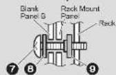
Mount the blank panel B.

More than one person is needed for this step.
Please ensure that tack screw and washers are assembled as shown below to avoid grounding through the rack mount and blank panel B.
STEP

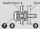
Mount the blank panel A.
Please mount
panel with
sticker on back side oriented
side, oriented as indicated on
sticker.

Please ensure that tack screw and washers are assembled as shown below to avoid grounding through the blank panel A.
CAUTIONS
* Not suitable For In-Wall Mounting.
* Do not ground through the rack mount.
* Do not mount the unit to the rack alone, need one more person to hold the unit.
Read "Important Safety Instruction" in the instruction manual and install the audio product with caution to avoid blocking its ventilation.
Improper installation may cause a fire or injury.
- Ensure that there is adequate ventilation above and below the unit
(according to the unit's instruction manual.) - For products that have vents on the side panels, please do not obstruct. In order to allow for ventilation.
- Do not cover the ventilation holes on the unit installed.
- For products that generate heat, such as an Amplifier or Receiver, please use a minimum of one "U" (1.75") blank panel (or space) above and below product for ventilation.
For best performance, it is recommended that DVD/CD players should be rack mounted below receivers to protect laser mechanisms. - If rack is installed in a warm or enclose environment, use a cooling fan for ventilation.
* Please use caution when rack mounting products. To balance the weight and to keep the center of gravity as low as possible (in order to keep from being too top heavy) mount heavier products towards the bottom of the rack.
Rack Mount Kit Instruction Manual
PARTS ENCLOSED
1

②

- Rack Mount Panels
• Actual panels may vary by model. - Blank panel A
- Blank panel B (For 120 mm (4.7") height model)
- Blank panel B (For 130 mm (5.1") height model)
- Spacer (For 130 mm (5.1") height model)
- Screws A
• For attaching the Rack Mount Panles to the
Unit (STEP 2) - Screws B
- Washers A
- Washers B
3

4

5

6


STEP

Remove screws from the right side of the cover.

Do not remove feet from the unit. Remove side screws only from cover as indicated.
STEP

If the height of the unit being mounted is 155 mm (6.1") (→P2)
If the height of the unit being mounted is 120 mm (4.7") or 130 mm (5.1") (→P3 - 4)
STEP STEP

For 155 mm (6.1") model For 120 mm (4.7") and 130
Align the rack mount to front panel of the unit.

Repeat the same procedure (step 1 - 2) for the left side.
Align the top corner of the rack mount panel to the top of the front panel first then align it vertically to the front panel.
After installing the rack mount panel on the right side, repeat the same procedure (step 1 - 2) for the left side.
Caution! When you install the rack mount panels, do not use any screws other than those included in the package.
Make sure to use correct screw type and the rack mount panel is positioned correctly.

natural_image
Four technical diagrams showing mechanical joint configurations with no text or symbolsSTEP

Mount the unit to the rack system.
Please see caution
section (→P4)
for ventilation
specifics.
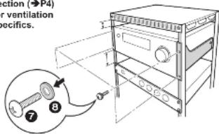
More than one person is needed for this step.
Please ensure that tack screw and washers are assembled as shown below to avoid grounding through the rack mount.

STEP

Mount the blank
panel A.
Please mount
panel with
sticker on
back side,
oriented as
indicated on
sticker.

Please ensure that tack screw and washers are assembled as shown below to avoid grounding through the blank panel A.

mm (5.1")
model

Align the rack mount to front panel of the unit.

Repeat the same procedure (step 1 - 2) for the left side.
Align the bottom corner of the rack mount panel to the bottom of the front panel first then align it vertically to the front panel.
After installing the rack mount panel on the right side, repeat the same procedure (step 1 - 2) for the left side.
Caution ! When you install the rack mount panels, do not use any screws other than those included in the package.
Make sure to use correct screw type and the rack mount panel is positioned correctly.

natural_image
Four-step diagram showing a mechanical component with circular features and prohibition signs (no text or symbols)STEP

Mount the unit to the rack system.
Please see caution
section (→P4)
for ventilation
specifics.

More than one person is needed for this step.
Please ensure that tack screw and washers are assembled as shown below to avoid grounding through the rack mount.

STEP 4 - 5

- CAUTIONS
- Rack Mount Kit Instruction Manual
- PARTS ENCLOSED
- STEP STEP
- For 155 mm (6.1") model For 120 mm (4.7") and 130
- Caution! When you install the rack mount panels, do not use any screws other than those included in the package.
- STEP
- mm (5.1")
- model
- Caution ! When you install the rack mount panels, do not use any screws other than those included in the package.
Brand : ONKYO
Model : IRK1553D
Category : Rack Mount Kit