
MXA-FMK-10 - Support de montage en rack AMX - Free user manual and instructions
Find the device manual for free MXA-FMK-10 AMX in PDF.


| Brand | AMX |
| Model | MXA-FMK-10 (also known as MSA-RMK-10, FG2265-14) |
| Product Type | Rack Mount Kit for Modero S Series Touch Panel |
| Compatible Device | MSD-1001 10.1" Modero S Series Wall Mount Touch Panel |
| Dimensions (HWD) | 6.97" x 19.00" x 2.15" (17.70 cm x 48.26 cm x 5.45 cm) |
| Weight | 2.60 lbs (1.47 kg) |
| Included Accessories | 4x #8-32 x 1.00 PPH screws, 4x #10-32 x 0.625 PH.TRUSS black screws, 4x #10 black nylon washers |
| Rack Standard | Standard 19-inch equipment rack |
| Installation Method | Rack mount using included screws and back box of touch panel |
| Max Screw Torque | 5 IN-LB (56 N-CM) for back box installation screws |
| Orientation | Install flanges facing away from front of rack |
| Material | Metal rack mount panel, plastic back box |
| Color | Black (typical) |
| Safety Warning | Do not exceed 5 IN-LB torque; excessive torque may strip holes or damage plastic back box |
| Ventilation Consideration | Ensure adequate air circulation to prevent overheating; rack doors may not close due to panel size |
| Additional Documentation | Refer to MSD/T-1001 Operation Reference Guide at www.amx.com |
Frequently Asked Questions - MXA-FMK-10 AMX
User questions about MXA-FMK-10 AMX
0 question about this device. Answer the ones you know or ask your own.
Ask a new question about this device
Download the instructions for your Support de montage en rack in PDF format for free! Find your manual MXA-FMK-10 - AMX and take your electronic device back in hand. On this page are published all the documents necessary for the use of your device. MXA-FMK-10 by AMX.
USER MANUAL MXA-FMK-10 AMX
The MSA-RMK-10 Modero S Series ® Rack Mount Kit (FG2265-14) is an optional accessory for the MSD-1001 10.1" Modero S Series Wall Mount Touch Panel (FIG. 1). The kit allows the touch panel to be mounted directly on an equipment rack, and includes a rack mount frame, screws and washers.

FIG. 1 MSA-RMK-10
Product Specifications
| MSA-RMK-10 (FG2265-14) SPECIFICATIONS | |
| Dimensions (HWD): 6.97" x 19.00" x 2.15" (17.70 cm x 48.26 cm x 5.45 cm) | |
| Weight: | 2.60 lbs (1.47 kg) |
| Included Accessories: | Screws (4), #8-32 X 1.00, PPH (80-0140)Screws (4), #10-32 X .625, PH.TRUSS, BLK (80-0186)Washers (4), #10, BLACK NYLON (80-0342) |
Installation of the MSA-RMK-10
The MSA-RMK-10 offers a stable installation mount for the MSD-1001 through the panel's Back Box.
NOTE: All doors, covers, and other obstacles preventing installation of the Rack Mount Kit should be removed before installation is attempted. Due to the size of the Modero S Series panel, it may not be possible to close racks that contain a rack door, once installation is complete.
To install the MSA-RMK-10:
- Secure the Rack Mount Panel to the rack with #10-32 screws. Make sure that the installation flanges face away from the front of the rack (FIG. 2).
- Insert the Back Box into the Rack Mount Panel, making sure that the Back Box is in the correct orientation. The stand-offs on the installation flanges will pass through the Back Box and help anchor it in place.
- Use the #8-32 screws to attach the Back Box to the stand-offs. Note that the Rack Mount Panel has four stand-offs.
WARNING: The maximum recommended torque to be used on the Back Box installation screws is 5 IN-LB [56 N-CM]. Applying excessive torque while tightening the screws, such as with powered screwdrivers, can strip out the screw holes or damage the plastic back box..
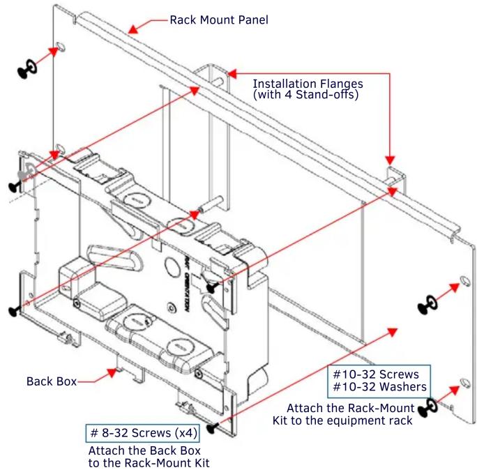
FIG. 2 INSTALLATION OF THE BACK BOX INTO THE MSA-RMK-10, FRONT VIEW
- With the Back Box anchored in the Rack Mount Panel (FIG. 3), you may now install the MSD-1001 into the Back Box.

FIG. 3 FINAL ASSEMBLY OF THE MSA-RMK-10 WITH BACK BOX
NOTE: For more information on installing the MSD-1001 into its back box, please refer to the MSD/T-1001 Operation Reference Guide, available from www.amx.com.
A Note About Wall and Rack Installation
Some products are installed in areas of differing temperature and cooling methodologies. These include products installed in walls, racks, cabinets, etc. The areas may have different temperatures and/or cooling approaches that must be taken into consideration to maintain the product within the specified operating temperature.
FIG. 4 shows an AMX device installed in a wall with a filled volume (such as with insulation or concrete), as well as with a closed volume (such as between studs in an otherwise finished wall). The diagram shows how heat generated by the device or other devices may have no way to escape, and may build up to levels that may affect device operation.
Installation Recommendations
During any installation, a lack of ventilation may produce conditions that may adversely affect the device's operation. In these circumstances, special care must be made to make sure that temperatures within enclosed areas do device's maximum rated temperature.
Additional Documentation
For additional mounting options, accessories, or touch panel information, refer to the documentation available at www.amx.com.

FIG. 4 HEAT CONVECTION IN FILLED OR CLOSED VOLUME, LIMITED OR NO CONVECTION
In FIG. 5, the diagram displays an AMX device in a typical rack mounting, with full air circulation around the front and back of the device. In this case, the main concern is with heat building up between components, possibly to levels that may affect device operation.
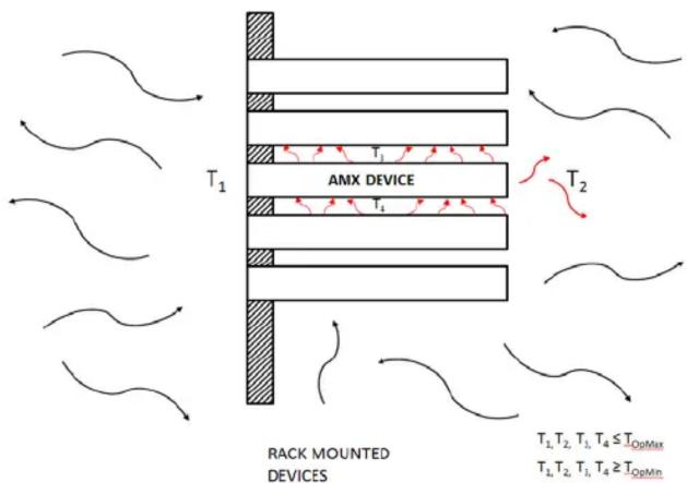
FIG. 5 HEAT CONVECTION IN RACK-MOUNTED DEVICES
Brand : AMX
Model : MXA-FMK-10
Category : Support de montage en rack