
EB6 - Range hood BEST - Free user manual and instructions
Find the device manual for free EB6 BEST in PDF.


| Product Type | Range Hood |
| Brand | Best |
| Model | EB6 |
| Width | 600 mm |
| Depth | 500 mm |
| Height | 150 mm |
| Weight | 10 kg |
| Power Supply | 220-240 V, 50 Hz |
| Extraction Rate | 650 m³/h |
| Noise Level | 65 dB(A) |
| Filter Type | Aluminum grease filter |
| Lighting | LED, 2 x 3 W |
| Controls | Push buttons |
| Functions | Extraction, recirculation, lighting |
| Cleaning & Maintenance | Clean filters monthly with warm soapy water |
| Safety Features | Overheat protection, automatic shut-off |
| Spare Parts | Filters and LED bulbs available |
| Repairability | Filters and bulbs user-replaceable |
Frequently Asked Questions - EB6 BEST
User questions about EB6 BEST
0 question about this device. Answer the ones you know or ask your own.
Ask a new question about this device
Download the instructions for your Range hood in PDF format for free! Find your manual EB6 - BEST and take your electronic device back in hand. On this page are published all the documents necessary for the use of your device. EB6 by BEST.
USER MANUAL EB6 BEST
natural_image
Line drawing of a closed book with visible spine and cover (no text or symbols)Model EB6
Model EB9
For use with compatible
Best by Broan range hoods.
See hood manual for suitability.
READ AND SAVE THESE INSTRUCTIONS
WARNING
TO REDUCE THE RISK OF FIRE, ELECTRIC SHOCK, OR INJURY TO PERSONS, OBSERVE THE FOLLOWING:
- Use this unit only in the manner intended by the manufacturer. If you have questions, contact the manufacturer at the address or telephone number listed in the warranty.
- Before servicing or cleaning unit, switch power off at service panel and lock the service disconnecting means to prevent power from being switched on accidentally. When the service disconnecting means cannot be locked, securely fasten a prominent warning device, such as a tag, to the service panel.
- Installation work and electrical wiring must be done by a qualified person(s) in accordance with all applicable codes and standards, including fire-rated construction codes and standards.
- Sufficient air is needed for proper combustion and exhausting of gases through the flue (chimney) of fuel burning equipment to prevent backdrafting. Follow the heating equipment manufacturer's guideline and safety standards such as those published by the National Fire Protection Association (NFPA), and the American Society for Heating, Refrigeration and Air Conditioning Engineers (ASHRAE),
WARNING
- When cutting or drilling into wall, or ceiling, do not damage electrical wiring or other hidden utilities.
- Ducted fans must always be vented to the outdoors.
- To reduce risk of fire, use only metal ductwork.
- This unit must be grounded.
CAUTION
- For general ventilating use only. Do not use to exhaust hazardous or explosive material and vapors.
- To avoid motor bearing damage and noisy and/or unbalanced impellers, keep drywall spray, construction dust, etc. off power unit.
- Please read specification label on product for further information and requirements.
- Electrical circuit, including speed control, (if used), must be rated 6 AMPS minimum for Model EB9 or 3 AMPS minimum for Model EB6.
INSTALLER: Leave This Manual With The Homeowner.
HOMEOWNER: Use And Care Information On Page 4.
SPECIFICATIONS
| MODEL VOLTS AMPS CFM DUCT SIZE | ||||
| EB6 120 | 2.4 600 10" | DIA. | ||
| EB9 120 | 5.7 900 10" | DIA. | ||
PLAN THE INSTALLATION
ALL INSTALLATIONS
- Locate the blower so the length of the duct run and number of elbows are kept to a minimum.
- Where possible, blower should be centered between wall studs or roof rafters.
PLAN THE INSTALLATION
- Avoid pipes, wires, or other ductwork that may be running through the wall.
- Attach mounting plate to top of hood.
- Install 10" dia. ductwork and 120 VAC house wiring between blower location and hood location.
PREPARE THE INSTALLATION LOCATION
ROOF INSTALLATIONS
- Locate the blower on the rear slope of the roof. Place it in a location to minimize duct run. The location should be free of obstacles (T.V. leads, electrical lines, etc.). Bear in mind, if the blower top is level with the roof peak, it will not be seen from the street. Keep this approximate location in mind as you work from within the attic.
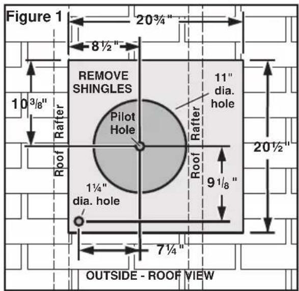
From inside the attic space:
- Drill a PILOT HOLE up through the roof, 8½" from the inside edge of a ROOF RAFTER.
From outside - on the roof:
-
Measure and mark the 20^3/4 " x 20^1/2 " rectangle. Cut and remove only the shingles inside this rectangle.
-
Measure and mark the 11" DIAMETER HOLE and the 1¼" DIAMETER HOLE. Cut these holes all the way through the roof.

- For flat roof installations, build a curb that will mount the blower at a minimum pitch of 2/12. See Figure 2. Discharge end of the blower should be pointed away from prevailing winds.
PREPARE THE INSTALLATION LOCATION
WALL INSTALLATIONS
- Choose a position on the outside wall. Make sure that no wall studs, pipes or wires run through the opening area.

From inside the wall:
- Drill a PILOT HOLE through the wall, 8 ^1/2 " from the inside edge of a WALL STUD.
From outside - on the wall:
-
Measure and mark the 24 ^3/4 " x 28 ^1/4 " rectangle. Cut and remove only the sid-ing inside this rectangle.
-
Measure and mark the 11" DIAMETER HOLE and the 1¼" DIAMETER HOLE. Cut these holes all the way through the wall.
PREPARE THE BLOWER
ALL INSTALLATIONS
- Unpack the blower assembly.
- Remove the cover and screws.
- Remove and discard cardboard from blower wheel.
- Remove the wiring box cover and screws.
- Attach an appropriate U.L. approved cable connector in the hole at the rear of the wiring box.
ROOF INSTALLATIONS
- Remove roofing nails from the upper 2/3 of the shingles around the cutout area and carefully lift the shingles to allow the back flashing sheet on the blower housing to fit under them.
- Center the blower ring in the 11" diameter hole, making sure that the 1-1/4" diameter electrical wiring hole aligns with the hole in the wiring box.
- Attach the blower to the roof with the six screws provided. All six holes in the back panel must be filled, or any moisture that may get inside the housing could leak into the house.
- Using a good grade of roofing cement, seal all of the shingles around the housing and flashing sheet as well as the mounting screw heads.
- Bring electrical wiring (from hood) through the hole in the wiring box and secure it according to local codes.

- Make the electrical connections with the proper connector for the type of wiring being used. Connect white to white, black to black, and the green or bare wire to green. See Figure 4, as well as the wiring label on the hood's mounting plate.
- Replace wiring box cover and screws. Do not pinch wiring under the cover.
- Check for free movement of the damper before installing housing cover and screws.
- Turn on power and check operation of the blower.
WALL INSTALLATIONS
- Place a large bead of caulk on the back side of the housing along the outer edge.
- Center the blower ring in the 11" diameter hole, making sure that the 1-1/4" diameter electrical wiring hole aligns with the hole in the wiring box.
- Attach blower to the wall with the six screws provided. All six holes in the back panel must be filled, or any moisture that may get inside the housing could leak into the house.
- Using a good grade of caulk, seal all around the mounting screw heads.
- Bring electrical wiring through the hole in the wiring box and secure it according to local codes.
- Make the electrical connections with the proper connector for the type of wire being used. Connect white to white, black to black, and green or bare wire to green. See Figure 4.
- Replace wiring box cover and screws. Do not pinch wiring under cover.
- Check for free movement of the damper before installing housing cover and screws.
- Turn on power and check operation of the blower.
- Top and side flanges of the back plate may be covered with trim strips. Do not block grille opening at bottom with trim. It will adversely affect performance of the blower.
USE AND CARE
Disconnect electrical power supply and lock-out service panel before cleaning or servicing this unit.
CLEANING
Remove cover and carefully vacuum blower and inside of housing. Be careful not to bend or otherwise damage blower wheel.
MOTOR LUBRICATION
The motor is permanently lubricated. Do not oil or disassemble motor.
BROAN ONE YEAR LIMITED WARRANTY
Broan warrants to the original consumer purchaser of its products that such products will be free from defects in materials or workmanship for a period of one year from the date of original purchase. THERE ARE NO OTHER WARRANTIES, EXPRESS OR IMPLIED, INCLUDING, BUT NOT LIMITED TO, IMPLIED WARRANTIES OF MERCHANTABILITY OR FITNESS FOR A PARTICULAR PURPOSE.
During this one-year period, Broan will, at its option, repair or replace, without charge, any product or part which is found to be defective under normal use and service.
THIS WARRANTY DOES NOT EXTEND TO FLUORESCENT LAMP STARTERS AND TUBES. This warranty does not cover (a) normal maintenance and service or (b) any products or parts which have been subject to misuse, negligence, accident, improper maintenance or repair (other than by Broan), faulty installation or installation contrary to recommended installation instructions.
The duration of any implied warranty is limited to the one-year period as specified for the express warranty. Some states do not allow limitation on how long an implied warranty lasts, so the above limitation may not apply to you.
BROAN'S OBLIGATION TO REPAIR OR REPLACE, AT BROAN'S OPTION, SHALL BE THE PURCHASER'S SOLE AND EXCLUSIVE REMEDY UNDER THIS WARRANTY. BROAN SHALL NOT BE LIABLE FOR INCIDENTAL, CONSEQUENTIAL OR SPECIAL DAMAGES ARISING OUT OF OR IN CONNECTION WITH PRODUCT USE OR PERFORMANCE. Some states do not allow the exclusion or limitation of incidental or consequential damages, so the above limitation or exclusion may not apply to you.
This warranty gives you specific legal rights, and you may also have other rights, which vary from state to state. This warranty supersedes all prior warranties.
To qualify for warranty service, you must (a) notify Broan at the address or telephone number below, (b) give the model number and part identification and (c) describe the nature of any defect in the product or part. At the time of requesting warranty service, you must present evidence of the original purchase date.
Best by Broan
P.O. Box 140
Hartford, WI 53027
SERVICE PARTS
MODELS EB6 & EB9
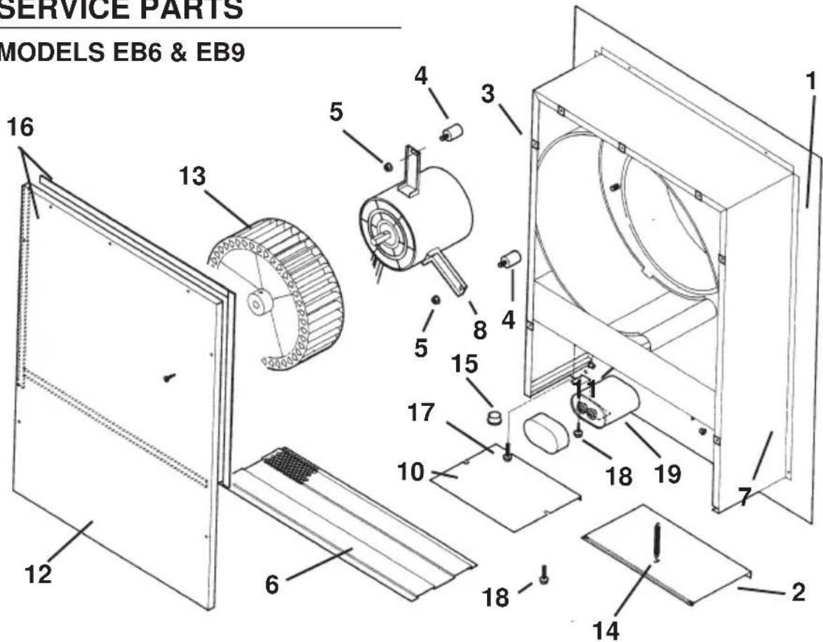
| KEYNO. | PART NO. DESCRIPTION |
| 1 97011795 Airbox Assembly2 98008507 Damper3 93260454 Sheet Metal Nut, #8-18 U-Type (7 req.)*4 99100484 Isolator (3 req.)5 99260477 Whiz Nut, 1/4" - 20 (3 req.)*6 98008511 Grille7 99100379 Heyco Damper (2 req.)8 99080396 Motor W/Capacitor (Model EB9)99080397 Motor W/Capacitor (Model EB6)10 98008509 Wiring Box Cover11 98008588 Capacitor Clamp12 98008510 Airbox Cover13 99020263 Blower Wheel (Model EB9)99020264 Blower Wheel (Model EB6)14 99140145 Damper Spring15 99400055 Heyco16 99100517 Foam Seal (4 req.)17 99150471 Hex Screw, #10 - 32 x 1/2"*18 99150535 Hex Screw, #8-16 x 3/8 (2 Req.)*19 99271110 Capacitor 15 MFD | |
* Standard Hardware - May be purchased locally. Always order replacement parts by Part No., not Key No.

- Model EB6
- Model EB9
- READ AND SAVE THESE INSTRUCTIONS
- WARNING
- TO REDUCE THE RISK OF FIRE, ELECTRIC SHOCK, OR INJURY TO PERSONS, OBSERVE THE FOLLOWING:
- CAUTION
- SPECIFICATIONS
- PLAN THE INSTALLATION
- ALL INSTALLATIONS
- PREPARE THE INSTALLATION LOCATION
- ROOF INSTALLATIONS
- WALL INSTALLATIONS
- PREPARE THE BLOWER
- USE AND CARE
- CLEANING
- MOTOR LUBRICATION
- BROAN ONE YEAR LIMITED WARRANTY
- Best by Broan
- SERVICE PARTS
- MODELS EB6 & EB9
Brand : BEST
Model : EB6
Category : Range hood