
Greenfire GFi750 - Frying Pan Regency - Free user manual and instructions
Find the device manual for free Greenfire GFi750 Regency in PDF.


| Type of Product | Pellet Stove |
| Brand | Regency |
| Model | Greenfire GFi750 |
| Category | Stove |
| Dimensions (H x W x D) | 24" x 22" x 21" |
| Weight | 250 lbs |
| Power Supply | 120V AC, 60Hz |
| Fuel Type | Wood Pellets |
| Hopper Capacity | 50 lbs |
| Heating Capacity | Up to 2,000 sq ft |
| Efficiency | 85% HHV |
| BTU Range | 12,000 - 45,000 BTU/hr |
| Venting Requirements | 3" or 4" Type L or PL vent |
| Ignition System | Automatic electric igniter |
| Controls | Digital thermostat with remote |
| Fan Type | Variable speed convection fan |
| Maintenance | Weekly ash removal, monthly burn pot cleaning |
| Safety Features | Overheat shutoff, cool-touch glass, tip-over switch |
| Warranty | Limited lifetime on firebox, 5 years on parts |
| Certification | EPA Phase II Certified, UL Listed |
Frequently Asked Questions - Greenfire GFi750 Regency
User questions about Greenfire GFi750 Regency
0 question about this device. Answer the ones you know or ask your own.
Ask a new question about this device
Download the instructions for your Frying Pan in PDF format for free! Find your manual Greenfire GFi750 - Regency and take your electronic device back in hand. On this page are published all the documents necessary for the use of your device. Greenfire GFi750 by Regency.
USER MANUAL Greenfire GFi750 Regency
Owners & Installation
Manual
LISTINGS AND CODE APPROVALS
These gas appliances have been tested in accordance with AS/NZS 5263.0 & AS/NZS 5263.1.3-2021 and have been certified by IAPMO for installation and operation as described in these Installation and Operating Instructions. Must be installed as per AS/NZS5601.
Your unit should be serviced annually by an authorised service person.

REGENCY®
FIREPLACE PRODUCTS
GFi750 GAS INBUILT

natural_image
Modern living room interior featuring a white brick fireplace, wooden furniture, and patterned rug (no visible text or symbols)Models: GFi750NG
GFi750LP
GFi750ULPG
PLEASE KEEP THESE INSTRUCTIONS FOR FUTURE REFERENCE
| WARNING:Improper installation, adjustment,alteration, service or maintenance cancause injury or property damage. Refer tothis manual. For assistance or additionalinformation consult an authorised installer,service agency or the gas supplier. | FOR YOUR SAFETYWhat to do if you smell gas:Do not try to light any applianceDo not touch any electrical switch: do not use any phone in your building.Immediately call your gas supplier from a neighbour's phone. Follow the gas supplier's instructions.If you cannot reach your gas supplier, call the fire department. |
| FOR YOUR SAFETYDo not store or use gasoline or otherflammable vapours and liquids in thevicinity of this or any other appliance. | |
| Installation and service must be performedby an authorised installer, service agencyor the gas supplier. |
TO THE NEW OWNER
Congratulations! You are the owner of a state-of-the-art Gas Inbuilt Fireplace by FPI. The Regency Gas Fireplace Series of appliances has been designed to provide you with all the warmth and charm of a fireplace, at the flick of a switch. The model GFi750 of this series has been approved by IAPMO for both safety and efficiency. As it also bears our own mark, it promises to provide you with economy, comfort and security for many trouble free years to follow. Please take a moment now to acquaint yourself with these instructions and the many features of your Regency Fireplace.

WARNING!

natural_image
Abstract illustration of two hands reaching toward a red circular shape with wavy lines (no text or symbols)HOT GLASS WILL CAUSE BURNS
DO NOT TOUCH GLASS UNTIL COOLED
Unit Dimensions - Flush Install (millimeters)
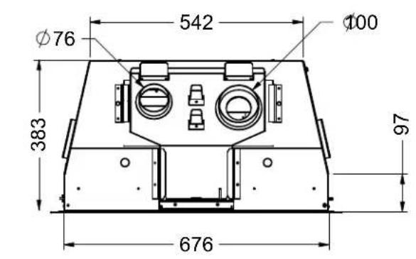


dimensions
Unit Dimensions - With Backing Plate (millimeters)
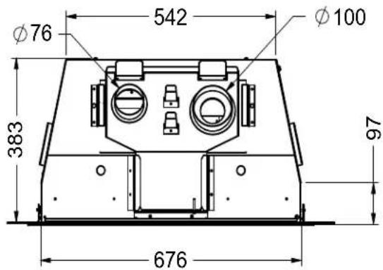

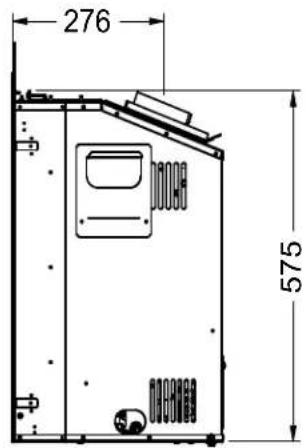
Table of Contents
Unit Dimensions - Flush Install (millimeters)....3
Unit Dimensions - With Backing Plate (millimeters) 4
Data Badge....6
Owner's Information
Important Message 7
For Your Safety 7
Materials Required....7
Before You Start....7
Installer's Information
Minimum Fireplace Opening 8
Installation Checklist....8
Installation
Clearances to Combustibles....9
Mantel Clearances 9
Gas Connection 9
Flueing 9
Flue Liner Installation 10
Gas Pipe Pressure Testing 10
885 S.I.T. Valve Description....10
Installation in Full Masonry Chimney....11
System Data - GFi750L 12
Aeration Settings....12
Conversion Kit #346-969 from NG to Propane/ULPG Model ...... 13
Glass Panel Installation (Part #346-906) 15
Log Set Installation 16
Primary Glass Guard Installation and Removal.... 19
Glass Door Installation and Removal 19
Faceplate Installation and Removal....20
Optional Zero Clearance Box Installation 21
Installation Instructions 23
3-Sided & 4-Sided Faceplate Installation 32
Backing Plate Installation 33
Final Check 34
Wiring 34
Standard Wiring 34
Operation
Lighting Procedure 35
Copy of Lighting Instruction Plate 36
Normal Operating Sounds Of Gas Appliances....37
Proflame II Remote Control Operating Instructions 38
Proflame II Battery Replacement & Battery Back Up 42
Maintenance
Maintenance Instructions....43
Log Replacement 43
Door Glass Replacement 43
Glass Gasket 43
Fan Removal and Installation Option 1 (Front)....44
Fan Removal and Installation Option 2 (Rear Fan Access)...... 45
Inner Panel Removal and Installation 46
IFC (Integrated Fireplace Control) Error Codes 47
Gas Appliance Maintenance....48
Parts
Main Assembly 49
Faceplate Assembly 50
Warranty 53
data badge
This is a copy of the label that accompanies each Regency GFi750 Gas Inbuilt fireplace. We have printed a copy of the contents here for your review.
Check the label on the unit and if there is a difference, the label on the unit is the correct one.
DATA BADGE NOTE: Regency units are constantly being improved.
Regency Gas Fireplace
Model


Gas Type
NG
PROPANE
ULPG
Model
GFi750NG
GFi750LP GFi750ULPG
| Gas Consumption High |
| Gas Consumption Low |
| Min. Supply Pressure |
| Manifold Pressure High |
| Manifold Pressure Low |
| Injector Size |
| 26 MJ/h |
| 16.9 MJ/h |
| 1.13 kPa |
| 0.87 kPa |
| 0.40 kPa |
| 1 x #42 |
| 2.37 mm |
| 26 MJ/h |
| 18.1 MJ/h |
| 2.75 kPa |
| 2.49 kPa |
| 1.59 kPa |
| 1.45 mm |
| 21.5 MJ/h |
| 17.7 MJ/h |
| 2.75 kPa |
| 2.49 kPa |
| 1.59 kPa |
| 1 x #55 |
| 1.32 mm |
AS/NZS 5263.0 & AS/NZS 5263.1.3
Approval No. GMK10782 SUITABLE ONLY FOR INDOOR INSTALLATION
Electrical: 240VAC 50Hz 1.0 amp

N2134
Western Australia:
Air Group Australia 131 Bannister Rd Canning Vale WA 6155
Eastern Australia:
Fireplace Products Australia Pty. Ltd. 99 Colemans Road Dandenong South Vic. Australia 3175
New Zealand:
Aber Holdings 17 Main Street Place Te Rapa, HA 3200
To be installed by an authorised person in accordance with installation instructions provided with the appliance.
Serial Number
571
920-473a

DO NOT OPERATE THIS APPLIANCE BEFORE READING THE INSTRUCTIONS BOOKLET.
DO NOT PLACE ARTICLES ON OR AGAINST THIS APPLIANCE
DO NOT STORE CHEMICALS OR FLAMMABLE MATERIALS NEAR THIS APPLIANCE.
DO NOT OPERATE WITH PANELS, COVERS OR GUARDS REMOVED FROM THIS APPLIANCE.
908-602c
THE GUARD IS FITTED TO THIS APPLIANCE TO REDUCE THE RISK OF FIRE OR INJURY FROM BURNS AND NO PART OF IT SHOULD BE PERMANENTLY REMOVED.
FOR PROTECTION OF YOUNG CHILDREN OR THE INFIRM, A SECONDARY GUARD IS REQUIRED.
Important Message
The Regency Gas Inbuilt must be installed in accordance with these instructions. Carefully read all the instructions in this manual first.
Note: Failure to follow these instructions could cause a malfunction of the heater which could result in death, serious bodily injury, and/or property damage. Failure to follow these instructions may also void your fire insurance and/or warranty.
For Your Safety
This appliance requires air for proper combustion. Always provide adequate combustion and ventilation air. Follow instructions and information in the current AS/NZS5601 or local codes. Consult the "authority having jurisdiction" to determine the need for a permit prior to starting the installation.
Materials Required
A 240 Volt AC power cord is hooked up to the unit. Plug 3 wire cord into a suitable receptacle. Do not cut the ground terminal off under any circumstances.
When connected with 240 volts, the appliance must be electrically grounded in accordance with local codes.
This unit is polarity sensitive and will not operate if polarity is incorrect.
WARNING: Suitable for installation into a masonry fireplace only.
Before You Start
Installation is to be carried out ONLY by an authorised person.
1) The appliance shall be installed in accordance with the manufacturer's installation instructions, local gas fitting regulations, municipal building codes, water supply regulations, electrical wiring regulations, with AS/NZS5601.
2) Installation and repair should be done ONLY by an authorised person.
3) The appliance should be inspected before use and at least annually by an authorised service person. More frequent cleaning may be required due to excessive lint from carpeting, bedding material, etc. It is imperative that control compartments, burners and circulating air passageways of the appliance be kept clean and free from excessive lint from carpeting.
4) See general construction and assembly instructions. This appliance may only be installed in a flued, non-combustible fireplace. The appliance and flue should be enclosed when installed or passing through a living area, where children may come in contact with it.
5) Always connect this space heater to a chimney and flue to the outside of the building envelope. Never flue to another room. Make sure that the flue is properly sized and is of adequate height to provide the proper draft.
6) Inspect the flueing system annually for blockage and any signs of deterioration.
7) Any safety glass removed for servicing must be replaced prior to operating the appliance.
8) To prevent injury, do not allow anyone who is unfamiliar with the operation to use the fireplace.
9) Only Regency flue kit part # 946-773 can be used. This flue kit contains all the components required to safely install this GFi750 gas inbuilt.
PACKAGING: The unit and its contents are packaged to prevent damage during transport. After unboxing, remove the cardboard spacers and plastic wrap and recycle or dispose of them properly. Carefully remove the logs from inside the box before commissioning it; unwrap each log and set aside. Refer to subsequent instructions on proper set up and safety check before commissioning the unit.
NOTE: TO BE INSTALLED ON A NON-COMBUSTIBLE FLOOR.
installer's information
Minimum Fireplace Opening
The minimum fireplace openings for the Regency GFi750 gas space heater are shown below:
| Lintel Depth (mm) | Height (mm) | Width Front (mm) | Depth (mm) | Width-Back (mm) |
| 200 590 685 | 400 565 |

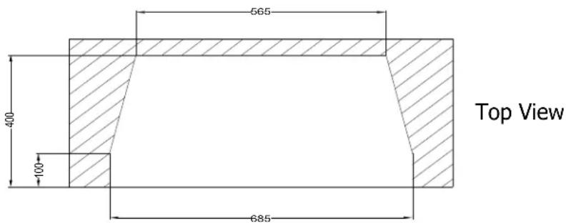
Installation Checklist
Before installing vent system ensure that the damper plate is open and secure to prevent the damper plate from falling down and crushing the liner.
The FPI Gas Inbuilt is installed as listed.
- Check all clearances to combustibles, (Refer to sections "Minimum Fireplace Opening and Clearances to Combustibles)
- Make the gas connection. (Refer to section "Gas Connection")
- Install the 76 mm and 102 mm flue liner to the sliding connector plate. (Refer to section "Flue Liner Installation.")
- Slide the unit half way into the fireplace.
- Pull the vent connector plate through the tapered brackets and fasten to the front plate. Refer to section "Flue Liner Installation.")
- Slide the unit fully into the fireplace.
- Test gas pressure (Refer to section "Gas Pipe Pressure Testing"). Check aeration system (Refer to section "Gas Insert Aeration System").
- Install standard and optional features. Refer to the following sections:
a. Log Set
b. Door, Primary Guard & Faceplate
c. Inner Glass Panels (optional)
- Final check: Before leaving this unit with the customer, the installer must ensure that the appliance is firing correctly. This includes:
a) Clocking the appliance to ensure the correct firing rate.
b) Adjusting the primary air and restrictor settings, if required, to ensure that the flame does not carbon.
Clearances to Combustibles
Minimum Clearances to Combustibles
From Unit
Sides A 180 mm
Ceiling B 1205 mm
Mantel C 330 mm
Max. Mantle Depth E 305 mm (see Dia. 2)
Min. Alcove Width F 1220 mm
Max. Alcove Depth G 915 mm
*No hearth required.

Mantel Clearances
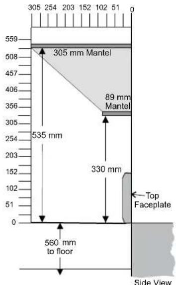
NOTES
- A non-combustible mantel may be installed at a lower height if the framing is made of metal studs covered with a non-combustible board.
- The non-combustible mantle when installed at a lower overall height may not be lower than 152 mm from the top of the fireplace opening.
Gas Connection
GAS CONNECTION WARNING: Only persons licensed to work with gas piping may make the necessary gas connections to this appliance.
1) If the appliance is to be installed into an existing chimney system, thoroughly clean the masonry fireplace.
2) The appliance is provided with an opening on the right hand side of the control compartment. The 9.5 mm flexible gas hose provided needs to be brought in from behind this opening. Ensure all gas connections are tight.
3) Locate the center point where the vent will pass through the chimney above the appliance. Move the appliance into the exact location where it is to be installed. Ensure that the Insert is level.

NOTE: Shut off valve must be installed in an accessible location.
Flueing
WARNING DO NOT USE AN UNLINED MASONRY CHIMNEY AS THE FLUE FOR THIS APPLIANCE. THE APPLIANCE MUST NOT CONNECT TO A CHIMNEY FLUE SERVING A SEPARATE SOLID FUEL BURNING APPLIANCE AND MUST BE TERMINATED TO THE OUTDOORS.
This appliance is designed to be attached to two co-linear aluminium flex pipes running the full length of the chimney. The flue length must be a minimum length of 2.44 m and a maximum of 10.7 m. See chart for minimum distances from roof. Periodically check that the vent is unrestricted.
Masonry chimneys may take various contours which the flexible liner will accommodate. However, keep the flexible liner as straight as possible, avoid unnecessary bending.
The Air Intake pipe must be attached to the inlet air collar of the adaptor.
946-773 Vertical Flue Kit
The flue kit contains the following:
Part #
948-305
948-336
46DVA-VCH
46DVA-34CLTA
Description
76mm Flex - 10.7m
102mm Flex - 10.7m
Termination Cap High Wind
Adaptor & Chimney Plate

Note: When installing the flueing, identify the flues. Mark one exhaust and one intake as indicated on the top of the unit.

natural_image
Diagram of a device with two circular annotations pointing to a central screen and two rectangular blocks below (no text or symbols present)Flue Restrictor Settings:
29 mm x 2 (Factory Set)
installation
Gas Pipe Pressure Testing
During pressure testing of the gas supply piping system at pressures equal to or less than 3.45 kPa, close the appliance's manual shut-off valve to isolated it from the gas supply. Disconnect the piping from the valve at pressures over 3.45 kPa.
The manifold pressure is controlled by a regulator built into the gas control and should be checked at the pressure test point.
- Make sure the unit is in the "OFF" position.
- Loosen the "IN" and/or "OUT" pressure tap(s), turning counterclockwise with a 3mm wide flat screwdriver.

- To properly check gas pressure, both inlet and manifold pressures should be checked using the valve pressure ports on the valve.
-
Attach manometer to "IN" and/or "OUT" pressure tap(s) using a 8mm ID hose.
-
Turn the unit on with the remote or wall switch.
-
The pressure check should be carried out with the unit burning and the setting within the limits specified on the safety label.
-
When finished reading the manometer, turn off the unit, disconnect the hose, and tighten the screw (clockwise) with a 3mm flat screwdriver.

Screw should be snug, but do not over tighten.
885 S.I.T. Valve Description
1) 6 Stage flame adjustment
2) Pilot adjustment
3) Outlet Pressure Tap
4) Inlet Pressure Tap
5) Pilot Outlet
6) Main Gas Outlet
7) Main Gas Inlet


Installation in Full Masonry Chimney
- Measure and record dimensions to determine total flex liner length requirements (see instructions below for details).
- Carefully feed the liner down the chimney and out through the damper. One person should feed the liner through the chimney, and another person should pull the liner from the bottom.
- After carefully feeding the Flex Liner down the chimney to the bottom, form and angle to line up the Flex Liner with the vent opening on the appliance.
Important: Do not let the flex liner sag below the level at which it will connect to the appliance or connector. This could allow hot gas to become trapped and potentially become a fire hazard. The Flex Liner path should always be sloped up toward the termination cap.
- Temporarily secure the flex liner at the top of the chimney. Be sure to leave 76 mm of flex above the existing chimney to allow for connection to the termination cap (chimney plate and termination cap).

- Repeat Steps 1-4 for second length of Flex Liner.
- At the top of the chimney, slide the chimney plate over the two ends of the Flex Liner and secure it to the surrounding masonry using masonry anchor bolts. Before installing the chimney plate, run a bead of non-hardening seal and between the chimney plate and the masonry to prevent moisture from entering the chimney.
Note: Verify that there is sufficient room to mount the chimney plate on to the masonry. You must have a level surface in order to install the chimney plate properly.
- Add a bead of Mill-pack sealant to each collar on the Co-Linear to Co-Axial adaptor. Attach the Flex Liner ends at the top of the chimney to the Co-Linear to Co-Axial adaptor. Use four sheet metal screws to connect each Flex Liner run to the Co-Linear to Co-Axial adaptor.
-
Install termination cap.
-
Add a bead of Mill-pack sealant to each collar at appliance end. Connect the Co-Linear Flex to the two outlets on the top of the appliance using four sheet metal screws each. See the appliance manufacturer's instructions for details. Make sure the Flex Liners do not sag behind the appliance. Finally, move the appliance into its appropriate place. Mount the Adaptor to the chimney plate using sheet metal screws.
Note: The unit needs to be installed on a flat solid continuous base. The base may be metal, concrete or masonry. Installing the unit on an unleveled base may cause vibration or excess fan noises.
| Roof Pitch Minimum Flue Height | |
| flat to 30.26° | 0.61 |
| over 30.26°to 33.69° | 0.61 |
| over 33.69°to 36.37° | 0.61 |
| over 36.37°to 39.81° | 0.76 |
| over 39.81°to 42.51° | 0.99 |
| over 42.51°to 45.00° | 1.22 |
| over 45.00°to 49.40° | 1.52 |
| over 49.40°to 53.13° | 1.83 |
| over 53.13°to 56.31° | 2.13 |
| over 56.31°to 59.04° | 2.29 |
| over 59.04°to 60.26° | 2.44 |
Install to AS5601 (Australia) / NZS 5262 (New Zealand)
NOTE Flue plate connector gasket must not be damaged or removed. Care must be take to ensure that this gasket remains intact to prevent flue leakage.
installation
| System Data - GFi750 | |||
| GFi750NG: For 0 to 610 meters altitudeGFi750LP: For 0 to 610 meters altitudeGFi750ULPG: For 0 to 610 meters altitude | |||
| Burner Inlet Orifice Sizes:NG Propane ULPGBurner #42 1.45mm #55 | |||
| Max. InputNG 26 MJ/hPropane 26 MJ/hULPG 21.5 MJ/h | |||
| Min. InputNG 16.9 MJ/hPropane 18.1 MJ/hULPG 17.7 MJ/h | |||
| Supply PressureNG 1.13 kPaPropane 2.75 kPaULPG 2.75 kPa | |||
| Manifold Pressure HIGH LOWNG 0.87 kPa 0.4 kPaPropane 2.49 kPa 1.6 kPaULPG 2.49 kPa 1.6 kPa | |||
| Electrical: 240 V. 50Hz.Circulation: Off/Low to High Fan SpeedLog Set: 13 per set | |||
| Aeration SettingNG 5 mm openPropane Fully openULPG Fully open |
Aeration Settings
The burner aeration is factory set but may need adjusting due to either the local gas supply, air supply or altitude. This adjustment is performed by the installer. (Close the aeration for a more yellow flame, or open it to make the flame bluer).
NG: 5mm open
Propane: Fully open
ULPG: Fully open

- Any damage due to carboning resulting from improperly setting the aeration and restrictor setting controls is NOT covered under warranty.
Conversion Kit #346-969 from NG to Propane/ULPG Model
THIS CONVERSION MUST BE DONE BY A QUALIFIED GAS FITTER IF IN DOUBT DO NOT DO THIS CONVERSION!
WARNING
This conversion kit shall be installed by a qualified service agency in accordance with the manufacturer's instructions and all applicable codes and requirements of the authority having jurisdiction. If these instructions is not followed exactly, a fire, explosion or production of carbon monoxide may result causing property damage, personal injury or loss of life. The qualified service agency is responsible for the proper installation of this kit. The installation is not proper and complete until the operation of the converted appliance is checked as specified in the manufacturer's instructions supplied with the kit.
Conversion Kit includes:
| 1 911-011 Stepper Motor LP for 885 SIT |
| 1 905-081 Propane Orifice 1.45 mm |
| 1 904-977 ULPG orifice |
| 1 910-037 Pilot Orifice #30 |
| 1 918-590 Decal - Conversion to LP |
| 1 919-728 Orange 'PROPANE" Label |
| 1 904-977 ULPG Orifice #55 |
| 1 918-272 Conversion to ULPG decal |
| 1 919-727 Red "UNIVERSAL LPG" Label |
| 1 904-529 4mm Allen Key |
| 1 920-534 Instruction Sheet |
CAUTION
The gas supply must be shut off prior to disconnecting the electrical power, before proceeding with the conversion.
Always let the appliance cool to room temperature before servicing.
- Remove faceplate, glass guard, door, logs and crushed glass media. (See instructions)
- Remove the burner by removing the 2 screws as shown below.
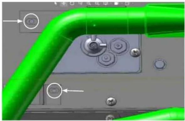
natural_image
Close-up of a green pipe fitting with two circular components and mounting holes (no text or symbols visible)- Remove 10 screws from the light housing and place it on the valve tray as shown below. Be careful not to tear the gasket located below the light housing.

natural_image
Close-up of a mechanical component with labeled 'TOP' and circular features, no readable text or symbols beyond the label
natural_image
Interior view of an industrial or mechanical assembly with metal components and wiring (no visible text or symbols)- Remove the screw from IFC mounting bracket and gently slide it out.

natural_image
Close-up of a wooden board with wires and components, no visible text or symbols- Disconnect the cable at IFC marked X5 coming from pressure regulator motor.
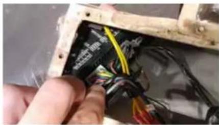
natural_image
Close-up of hands holding a damaged electronic component with visible wires and connectors (no text or symbols)CAUTION
Ensure that the wires do not touch underneath the firebox and light housing.
installation
-
Remove and discard 2 Pressure regulator screws (A) using a (T20 or slot screwdriver,) Pressure Regulator (B) and Spring and Diaphragm (C) (see below).
-
Ensure the rubber gasket, which is prefitted as part of the Assembly, is properly positioned. Install the new Pressure Regulator using the 2x M4 x .7 screws supplied. Tighten the screws to 25lb-in. In the event that the screw threads are cross threaded or stripped, replace the valve assembly.
Install the enclosed propane identification label to the valve body where it can be easily seen.

natural_image
Mechanical assembly diagram showing a motor and valve assembly with labeled components (A, B, C), no readable text or symbols present.- Re-attach the Pressure Regulator wire (disconnected in Step 5), and re-situate the IFC, secure the screw that fasten the IFC Mounting Bracket.
CAUTION Ensure that the wires do not touch underneath firebox and light housing.
- Remove burner orifice with a 9.5mm spanner. Use another spanner to hold on to the elbow behind the orifice. Discard orifice. Reinstall the new LP orifice stamped 1.45mm (or #55 ULPG) and tighten.

natural_image
Close-up of a mechanical component with a circular annotation highlighting a small feature, no visible text or symbols.Installer Notice: These instructions must be left with the appliance.
- Remove pilot retainer clip with pliers and pull off the pilot cap to expose the pilot orifice.

natural_image
Close-up of a mechanical assembly with no visible text or symbolsPilot retainer clip

natural_image
Close-up of a mechanical assembly with metal components and a clamped tool (no visible text or symbols)
natural_image
Close-up of a hand adjusting a mechanical component with a cylindrical component and two white components (no visible text or symbols)- Unscrew the pilot orifice with the allen key; then replace with the LPG pilot orifice #30 and re-tighten using the same allen key.

natural_image
Close-up of a hand holding a wrench and a small mechanical component, with no visible text or symbols.-
Reinstall pilot hood and pilot retainer clip removed in step 10.
-
Prior to installing burner - adjust aeration settings: Propane: Full Open ULPG: Full Open
Reinstall light housing and burner, see steps 3 and 2.
-
Ensure the pilot light is in the correct orientation to the Burner. Reconnect the gas and electrical supply to the appliance. Start the appliance. (see section on Lighting Instructions) Ensure that pilot and burner ignition is completed without delay. Check both your inlet and outlet pressures at full load. With a soapy solution, leak test the entire system. Verify both the correct flame and pilot appearance.
-
See Gas Pipe Pressure Testing section in the manual.
Note: Continuous Pilot (CPI Mode) is recommended for Propane/ULPG. (see page 28 of the manual or instructions included with the remote)
Optional Inner Glass Panel Installation (Part #346-906)
Note: Inner glass panel installation must be done prior to logs installation.
- Remove faceplate, glass guard, door, logs, crushed glass media, and burner (see instructions in this manual).
- Loosen the two screws securing the brackets that hold the side panels.
- Remove the two back brackets and set aside.

natural_image
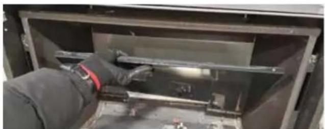
Interior view of a mechanical or electronic device with two circular annotations pointing to features (no visible text or symbols)- Remove the side panels by tilting the top in and lifting them out.

natural_image
Technical line drawing of a mechanical assembly with no visible text or symbols- Loosen the four screws and remove the mesh.
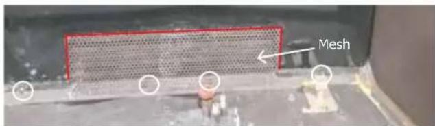
- Remove the back panel by tilting it forward, then lifting it up and out.
natural_image
Person in protective gear handling a metal panel inside a large industrial machine (no visible text or symbols)-
To install, do steps 5 to 1 in that order.
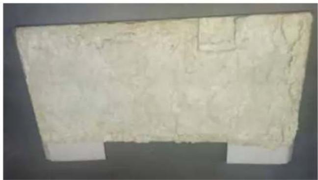
-
Remove the insulation from the rear inner metal panel and add it to rear inner glass panel. Recycle metal inner panel.
natural_image
White textured rectangular object with geometric patterns and a small dark base (no visible text or symbols)- To install, do steps 5 to 1 in that order.
Log Set Installation
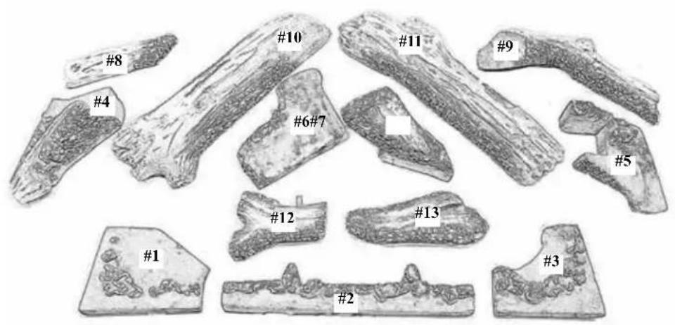
Read the instructions below carefully and refer to the diagrams. If logs are broken do not use the unit until they are replaced. Broken logs can interfere with the pilot operation. Carefully remove the logs from the box and unwrap them. The logs are fragile, handle with care - do not force into position.
Note: Install Optional Glass Inner Firebox Panels prior to installing logs.

1
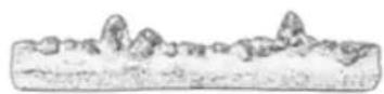
2
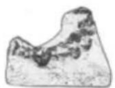
3

Panel #1 Panel #2 Panel #3
- Place the 3 base panels as shown above.
- Add 320 grams of 19 mm crushed glass on the light tray.

natural_image
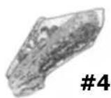
Simple line drawing of a window with a door and patterned surface (no text or symbols)- Place log #4 on the top left corner of firebox base.

5

natural_image
Simple line drawing of a bed with a tray and a hand holding an object (no text or symbols)- Place log #5 on the top right corner of firebox base.
6

natural_image
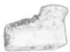
Simple line drawing of a person sitting at a desk with a ladder (no text or symbols)- Place log #6 as shown above. Maintain a gap between the log and the burner on the left side (see diagram 1).

7
natural_image
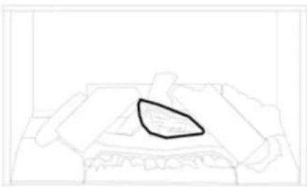
Simple line drawing of a desk with a laptop and a pen, no text or symbols present- Place log #7 as shown above. Maintain a gap between the log and the burner on the right side (see diagram 1).
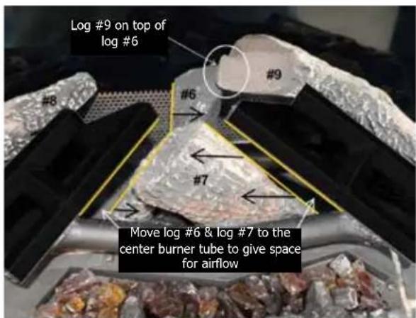
Diagram 1

natural_image
Simple line drawing of a rectangular object labeled #8 and a hand holding a knife, with no text or symbols present.- Place log #8 on log #4. Ensure log #8 is pushed against the rear panel.

natural_image
Two abstract line drawings: one resembling a bone-like structure labeled #9, the other showing a geometric shape (no text or symbols)- Place log #9 on log #5. Ensure log #9 is pushed against the rear panel and top of log #9 sits on top of log #6 (see diagram 1).
natural_image
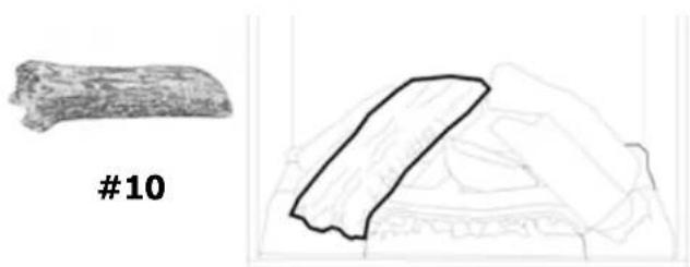
Two abstract line drawings: a textured, irregularly shaped object labeled #10 and a fragmented rectangular shape with curved lines (no text or symbols)- Place log #10 on left burner.
installation

natural_image
Two hand-drawn sketches: a textured rectangular object labeled #11 and a sketched abstract shape (no text or symbols)- Place log #11 on right burner.

natural_image
Two abstract line drawings: one resembling a tree or plant, the other showing a stylized bird silhouette (no text or symbols)- Place log #12 on the 2 notches located on base panel #2 (see diagram 2).

Diagram 2

natural_image
Two hand-drawn sketches: one resembling a bone fragment labeled #13, the other showing fragmented bone structures with a highlighted region (no text or symbols)- Place log #13 on the pin on log #12. Place the other end of log #13 on notch located on base panel #2 (see diagram 3).

Diagram 3

natural_image
Line drawing of a food item with sliced pieces on a plate (no text or symbols)- Spread the embers along the front panels and on crushed glass.
Primary Glass Guard Installation and Removal

natural_image
3D mechanical component with mounting holes and a directional arrow indicator (no text or symbols)
natural_image
Close-up of a metallic mechanical component with a labeled arrow pointing to a detail (no text or symbols present)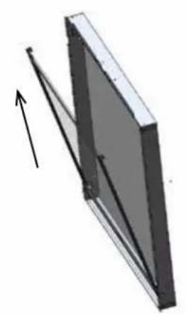
natural_image
3D diagram of a mechanical component with an upward arrow indicating direction (no text or symbols)Glass Door Installation and Removal
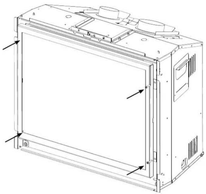
natural_image
Technical line drawing of a mechanical device casing with mounting brackets and internal components (no text or symbols)Optional Zero Clearance Box Installation
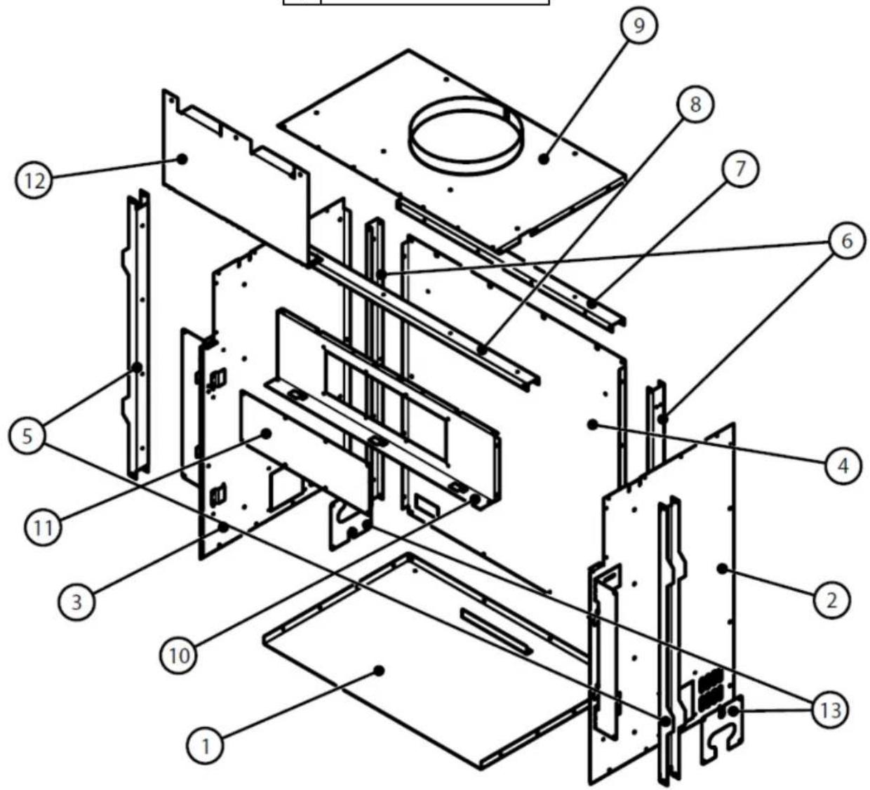
PART LIST
| # Description |
| 1 Base Panel Assembly |
| 2 Right Panel Assembly |
| 3 Left Panel Assembly |
| 4 Rear Panel Assembly |
| 5 Front Side Channel |
| 6 Rear Side Channel |
| 7 Rear Top Channel |
| 8 Front Top Channel |
| 9 Top Panel Assembly |
| # Description |
| 10 Front Panel Assembly |
| 11 Front Access Cover |
| 12 Top Header |
| 13 Side Access Cover |
| 14 Blunt Screw x 66 |
| 6 Pointed Screw x 10 |
| N/S Cowl |
| N/S Outer Flue |
| N/S Flex |
14

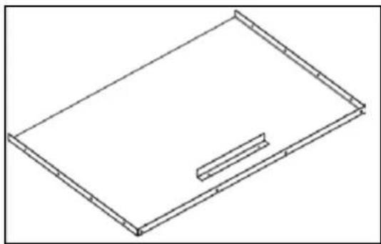
- Place Base Panel on the working surface.
natural_image
Isometric line drawing of a rectangular frame with a slot on top (no text or symbols)- Position Rear Panel and fasten with blunt screw.

natural_image
Isometric line drawing of a rectangular frame with corner markers and directional arrows (no text or symbols)- Install Right Panel with three screws from outside.

natural_image
Diagram of a 3D rectangular panel with internal components and directional arrows indicating movement (no text or symbols)- Fasten last screw from inside.

natural_image
Isometric line drawing of a 3D rectangular enclosure with internal partitions and a directional arrow (no text or symbols)- Repeat for the Left Panel.

natural_image
Isometric line drawing of a 3D rectangular frame with internal compartments and mounting holes (no text or symbols)- Install Rear Side Channel from outside, repeat on the other side.
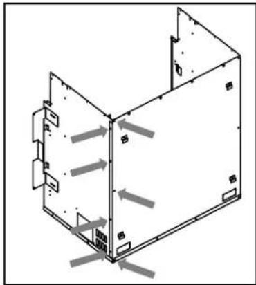
natural_image
Isometric technical diagram of a mechanical or electronic component with directional arrows indicating movement (no text or symbols present)- Install Front Side Channel from inside, repeat on the other side.
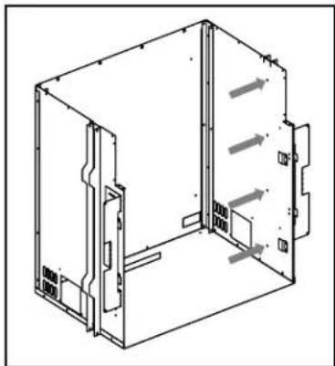
natural_image
Technical line drawing of a 3D rectangular enclosure with internal partitions and ventilation slots (no text or symbols)installation
- Install Front Top and Rear Top Channels, fasten both sides.

natural_image
Technical line drawing of a 3D mechanical enclosure or enclosure with internal components and mounting holes (no text or symbols)- Install Top Panel.

natural_image
Isometric technical drawing of a mechanical housing with directional arrows indicating flow or force (no text or symbols)- Install Front Panel. Use pointed screw x 2 on the lip. (View 13, 14)

natural_image
Technical line drawing of a mechanical housing or enclosure with mounting brackets and internal components (no text or symbols)- Install Top Nailing Strip.

natural_image
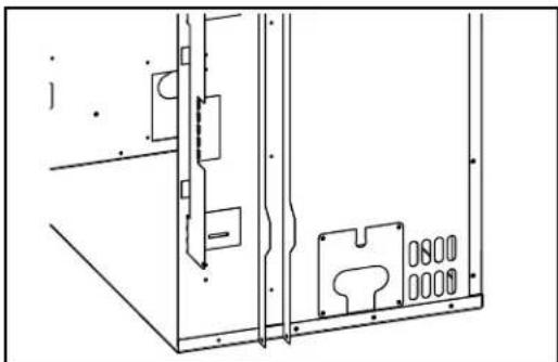
Technical line drawing of a mechanical housing or enclosure with mounting brackets and internal components (no text or symbols)- For Side Access, use wide opening for gas line.
natural_image
Technical line drawing of a mechanical assembly with mounting brackets and internal components (no text or symbols)- Use small opening for electrical cord with supplied grommet.

natural_image
Technical line drawing of a mechanical assembly with mounting brackets and internal components (no text or symbols)- Install Front Cover.

natural_image
Technical line drawing of a mechanical or electrical enclosure with internal components and directional arrows indicating flow or movement (no text or symbols)- Fold tab back on side nailing strip before frame installation.

natural_image
Technical line drawing of a server rack with a directional arrow indicating rotation (no text or symbols)CLEARANCES
The clearances listed below are minimum distances unless otherwise stated.
A major cause of chimney related fires is failure to maintain required clearances (air space) to combustible materials. It is of the greatest importance that this fireplace and flue system be installed only in accordance with these instructions.
| CAUTION | The top, back and sides of the fireplace are defined by standoffs. The metal ends of the standoff may NOT be recessed into combustible construction. |
| Clearance: Dimension Measured From: | ||
| A: Mantel Height (min.) | 406mm | Top of Fireplace Opening (Hot Air Outlet) |
| B: Sidewall (on one side) 178mm Side of Fireplace Opening | ||
| C: Ceiling (room and/or alcove) | 1067mm Top of Fireplace Opening | |
| D: Mantel Depth (max.) 305mm 420mm Above Fireplace Opening | ||
| E: Alcove Width 1524mm Sidewall to Sidewall (Minimum) | ||
| F: Alcove Depth 787mm Front to Back Wall (Maximum) | ||
| G: From Floor | 583mm | Top of Fireplace Opening (Hot Air Outlet) |
| Note: | 0 | No hearth required |
| WARNING | Fire hazard is an extreme risk. If these clearances (air space) to combustible materials are not adhered to. It is of greatest importance that this fireplace and flue system be installed only in accordance with these instructions. |
| Flue Clearances to Combustibles | |
| Around Flue | 51mm |
| NOTE | THE UNIT CAN BE INSTALLED ONTO A COMBUSTIBLE BASE. |


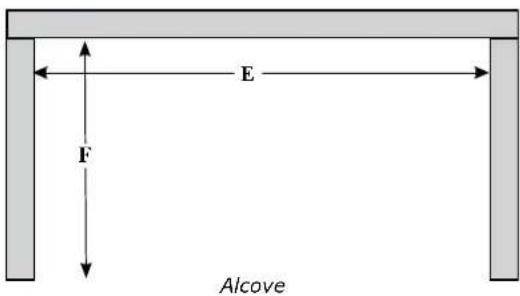
installation
UNIT DIMENSIONS


natural_image
Technical line drawing of a mechanical device with a central circular component and open panel (no text or symbols)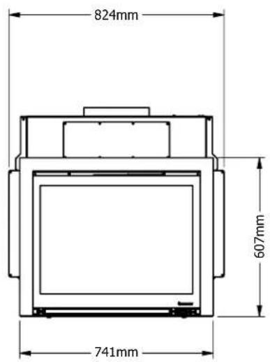
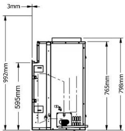
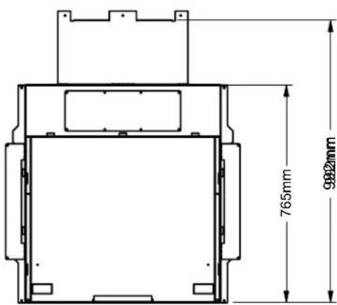
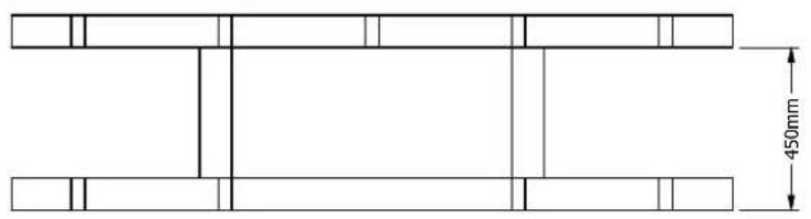
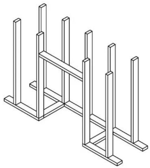
FRAMING DIMENSIONS
natural_image
Pure technical line drawing of a structural component with no text, numbers, or symbols
natural_image
Isometric line drawing of a structural frame with vertical supports (no text or symbols)installation
MANTEL DIMENSIONS

- Owners & Installation
- Manual
- REGENCY®
- FIREPLACE PRODUCTS
- GFi750 GAS INBUILT
- PLEASE KEEP THESE INSTRUCTIONS FOR FUTURE REFERENCE
- TO THE NEW OWNER
- WARNING!
- Unit Dimensions - Flush Install (millimeters)
- dimensions
- Unit Dimensions - With Backing Plate (millimeters)
- Table of Contents
- Owner's Information
- Installer's Information
- Installation
- Operation
- Maintenance
- Parts
- data badge
- Regency Gas Fireplace
- Important Message
- For Your Safety
- Materials Required
- Before You Start
- Minimum Fireplace Opening
- Installation Checklist
- Clearances to Combustibles
- From Unit
- NOTES
- Gas Connection
- GAS CONNECTION WARNING: Only persons licensed to work with gas piping may make the necessary gas connections to this appliance.
- Flueing
- 946-773 Vertical Flue Kit
- Part #
- Description
- Flue Restrictor Settings:
- Gas Pipe Pressure Testing
- S.I.T. Valve Description
- Installation in Full Masonry Chimney
- Aeration Settings
- Conversion Kit #346-969 from NG to Propane/ULPG Model
- THIS CONVERSION MUST BE DONE BY A QUALIFIED GAS FITTER IF IN DOUBT DO NOT DO THIS CONVERSION!
- WARNING
- CAUTION
- Always let the appliance cool to room temperature before servicing.
- Optional Inner Glass Panel Installation (Part #346-906)
- Note: Inner glass panel installation must be done prior to logs installation.
- Log Set Installation
- 1
- 2
- 3
- 5
- 6
- 7
- Primary Glass Guard Installation and Removal
- Glass Door Installation and Removal
- Optional Zero Clearance Box Installation
- PART LIST
- CLEARANCES
- UNIT DIMENSIONS
- FRAMING DIMENSIONS
- MANTEL DIMENSIONS
Brand : Regency
Model : Greenfire GFi750
Category : Frying Pan