
SP5NXCTUL - Loudspeaker Speco Technologies - Free user manual and instructions
Find the device manual for free SP5NXCTUL Speco Technologies in PDF.


| Product Type | Ceiling Speaker |
| Model | SP5NXCTUL |
| Brand | Speco Technologies |
| Driver Size | 5.25 inches |
| Impedance | 8 ohms (low impedance) / 70V/100V line transformer |
| Power Handling | 60W RMS (low impedance), 30W (70V/100V line) |
| Frequency Response | 70 Hz - 20 kHz |
| Sensitivity | 90 dB (1W/1m) |
| Dimensions (Cutout) | Diameter: 8.5 inches (216 mm) |
| Dimensions (Overall) | Depth: 3.5 inches (89 mm) |
| Weight | 1.5 kg (3.3 lbs) |
| Power Source | Passive (driven by amplifier) |
| Mounting | In-ceiling, with tile bridge or cutout |
| Grille | White, paintable, magnetic or twist-lock |
| Transformer Taps | 5W, 10W, 20W, 30W (for 70V/100V systems) |
| Dispersion | 120° conical |
| Material | Plastic baffle, metal grille |
| Safety | Do not expose to moisture or direct sunlight |
| Cleaning | Wipe with a dry, soft cloth |
| Installation | Professional installation recommended |
| Repairability | Replacement driver and transformer available |
| Wiring | Use 18-14 AWG speaker wire |
Frequently Asked Questions - SP5NXCTUL Speco Technologies
User questions about SP5NXCTUL Speco Technologies
0 question about this device. Answer the ones you know or ask your own.
Ask a new question about this device
Download the instructions for your Loudspeaker in PDF format for free! Find your manual SP5NXCTUL - Speco Technologies and take your electronic device back in hand. On this page are published all the documents necessary for the use of your device. SP5NXCTUL by Speco Technologies.
USER MANUAL SP5NXCTUL Speco Technologies
Frame Construction Ceiling Installation
1
Take the cutout template from the packaging box and punch out along the larger perforated circle. Place the cutout template against the bottom of the ceiling and trace the inside of it. Carefully cut out the ceiling material along the circle.

2
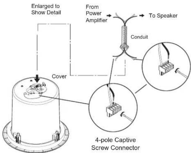
Remove the top cover to access the speaker connector. Attack the speaker wires to the 4-pole captive screw connector. Insert the 4-pole captive screw plug into the connector on back of the speaker. Install the conduit and secure the connections.
3
Replace the top cover and tighten the screws. Insert the speaker through the bottom of the hole in the ceiling.

flowchart
graph TD
    A["Power Amplifier"] --> B["Speaker 1"]
    A --> C["Speaker 2"]
    A --> D["Speaker 3"]
    B --> E["LED P"]
    B --> F["IN"]
    B --> G["R1 L00F"]
    C --> H["LED P"]
    C --> I["IN"]
    C --> J["R1 L00F"]
    D --> K["LED P"]
    D --> L["IN"]
    D --> M["R1 L00F"]
    E --> N["To Speakers"]
    F --> N
    G --> N
    H --> N
    I --> N
    J --> N
    K --> N
    L --> N
    M --> N
Parallel Hookup Wiring Diagram
4
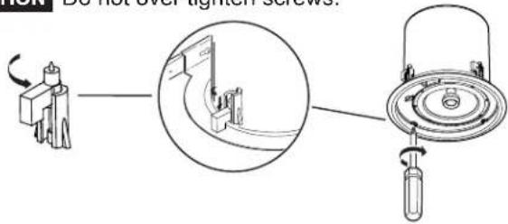
Loosen the four screws on the front baffle(counter clockwise) 1/2 turn. Then tighten the screws (clockwise) until the dog legs clamp the speaker to the ceiling.
CAUTION Do not over tighten screws.
5
Connect a secondary support line from the seismic tab to a secure support point. Set the rotary tap selector and install the speaker grille.

Specifications:
Acoustic & Electrical
Speaker type....
Frequency range......
Power handling....
Nominal sensitivity......
Nominal coverage angle......
Nominal impedance......
Transformer taps....
Woofer....
Tweeter....
Overload protection....
General
Temperature/humidity ......
10% to 90%, noncondensing
Operating: +32 to +122 °F (0 to +50 °C) /
10% to 90%, noncondensing
Listings UL1480
Compliances...... CE
Warranty ....Limited lifetime warranty*
NOTE: All nominal level are at ±10%.
NOTE: Specifications are subject to change without notice.
NOTE: Please see warranty card for full details.
2-way, ceiling speaker with metal back can
70 Hz to 20 kHz,
40 Watts RMS
80 Watts PEAK
88 dB, 1W@1m
110° conical coverage
8 ohms
70V: 10W, 5W, 2.5W, 1.3W, .63W, 8 ohms
100V: null, 10W, 5W, 2.5W, 1.3W, 8 ohms
5.25" (131 mm) polypropylene cone
with moisture resistant coating
3/4" (19 mm) silk dome
Full range power limiter with the 8 ohm direct
input only, protecting the tweeter, woofer, and
crossover.
Storage: -40 to +158 °F (-40 to +70 °C) /
10% to 90%, noncondensing
Operating: +32 to +122 °F (0 to +50 °C) /
10% to 90%, noncondensing
UL1480
CF
Limited lifetime warranty*
68-1065-01 Re v.B
06 06
Brand : Speco Technologies
Model : SP5NXCTUL
Category : Loudspeaker