
AS65C - Loudspeaker AudioSource - Free user manual and instructions
Find the device manual for free AS65C AudioSource in PDF.


| Product Type | In-Ceiling Speaker |
| Model | AS65C |
| Brand | AudioSource |
| Driver Configuration | 2-Way |
| Woofer Size | 6.5 inches (165 mm) |
| Tweeter Type | Dome Tweeter (Pivoting) |
| Impedance | 8 Ohms (typical) |
| Power Handling (RMS) | 5 - 125 Watts |
| Frequency Response | 50 Hz - 20 kHz (estimated) |
| Sensitivity | 89 dB (typical) |
| Overall Diameter | 8-7/16 inches (214 mm) |
| Cut-Out Diameter | 7-1/4 inches (184 mm) |
| Mounting Depth | 3-5/16 inches (84 mm) |
| Grille | Magnetic, Paintable |
| Terminal Type | Spring-Loaded Push Terminals |
| Mounting Clamps | Toggle Clamps (4) |
| Woofer Surround | Butyl Rubber |
| Warranty | Lifetime Limited |
| Recommended Wire Gauge | 16 AWG or larger for runs over 50 ft |
| Weight | Approx. 3 lbs (1.4 kg) |
Frequently Asked Questions - AS65C AudioSource
User questions about AS65C AudioSource
0 question about this device. Answer the ones you know or ask your own.
Ask a new question about this device
Download the instructions for your Loudspeaker in PDF format for free! Find your manual AS65C - AudioSource and take your electronic device back in hand. On this page are published all the documents necessary for the use of your device. AS65C by AudioSource.
USER MANUAL AS65C AudioSource
For: 6-1/2" In-Ceiling
Congratulations! You have purchased a high quality stereo loudspeaker. When matched to comparable electronic equipment, expect years of quality high fidelity sound. Our belief is that music matters and we are focused on delivering superlative music reproduction everywhere in your home.
The following manual is designed to give you, the installer or owner, basic information as to the speaker's installation and operation. It is beyond the scope of this manual to go into all the details that must be taken into consideration in a sophisticated high fidelity system. When installing the wiring and speakers it is important to adhere to all local codes and regulations. Consulting a professional can help to maximize your system's performance.
If you have any questions regarding this speaker which are not answered by this manual, contact your local dealer for assistance. For the most current information please visit AudioSource.net.
MINIMUM TOOLS REQUIRED
# 2 Phillips Head Screw Driver / Drill Driver Wire Cutter / Stripper
Other Possible Tools
Tape Measure, Pencil, Ladder, Drywall Saw, Stud-Finder, etc.
GENERAL DESCRIPTION
These two-way speakers have specially designed woofers with linear long throw butyl rubber surrounds for long life and superior damping. Dome tweeters are utilized for excellent high frequency dispersion throughout your entire listening environment.
SHIPPING DAMAGE
Each speaker is thoroughly tested before it leaves the factory. However, in shipment, accidents may occur. Please inspect your speakers carefully when you receive them to make sure there is no damage. If there is, please notify your dealer or supplier immediately for assistance. If you received your speakers by public transportation, report the damage immediately to the shipping company.
AMPLIFIER OPERATION
These speakers will perform well with amplifiers from 5 to 125 Watts RMS. However, damage to the speakers can be done by amplifiers of nearly any power rating if the amplifier is overdriven into clipping. "Amplifier clipping" is a phrase used to describe a condition when, because of the volume demand, an amplifier is being asked for more power than it can give. Clipping causes distortion of the audio signal. If you should hear an unusual amount of distortion at high listening levels then consider reducing the volume. DAMAGE DONE TO A SPEAKER BY CLIPPING IS NOT COVERED UNDER THE WARRANTY.
SPEAKER PLACEMENT
Placement of in-ceiling and in-wall speakers should be carefully considered. Please contact a professional for assistance if you are uncomfortable with the planning or installation process.
Ideally, the speakers should be located where they will provide the best possible sound and ease of installation. It is beyond the scope of this publication to discuss all of the various aspects of speaker placement, but here are some helpful suggestions.
For the front channels of a home theater we recommend that the speakers be placed between 18 and 36 inches (0.45m to 0.9m) from an adjacent wall/surface, as measured to the center of the hole. Avoid placing the speakers less than 12 inches (0.3m) from an adjacent wall. When placing speakers near a corner, avoid locating them an equal distance from the two adjacent surfaces.
If the drywall has not yet been installed, rough-in-kits are available to reserve the speaker location. The hole is then cut when the drywall is installed.
WIRING
To achieve maximum performance we recommend that the speaker cable be at least 16 gauge or larger for runs over 50 feet (15m) and that the cable be double insulated. A CL-2 or CL-3 rated cable may be required. Check local codes. "Zip cord," which is single insulated and is often made with clear insulation, should be avoided as it is not as durable. Allow about 2 12 feet (0.8m) of free cable at the speaker cut-out and sufficient length at the other end to reach the electronics. Having to add extra cable later can be tedious and time consuming.
Avoid bundling speaker cables parallel to electrical cables for extended lengths. Though the impedance is low and the likelihood of interference low, this may help reduce hum and RF interference. When securing the cable, use care not to staple or nail through the electrical conductors. Doing so could result in a short that might damage the electronics.
When connecting your speakers, make sure proper polarity (phasing) is maintained. Simply put, this means ensuring the same wire which is connected to the positive terminal of the amplifier has its other end connected to the positive terminal of the speaker. It is important to check this on all speakers. If the connections on one of the speakers are reversed, (out of phase) the sound quality will be impaired.
INSTALLATION
If the speaker locations have not yet been established then do so now. If possible, assess the area behind the ceiling for possible concealed obstructions such as wiring, heating ducts, cross-bracing etc. Absence of a crawl space will require greater study of observable clues and may also require the use of inspection holes and inspection tools (camera, mirror, flashlight, etc.). Use an “electronic stud finder” to locate the positions of the joists or studs. We recommend that the edge of the speaker
| Overall | Cut-Out (Round x Depth) | |
| AS65C | 8-7/16" round | 7-1/4" x 3-5/16" |
| AS61C | 8-7/16" round | 7-1/4" x 3-5/16" |
holes be at least 3/4" (19mm) away from joists or studs whenever possible to allow clearance for the toggle clamps.
Once the speaker locations are established use the cardboard template or the plastic compass provided with your speaker to draw the speaker cut-out. The hole diameters for the various speakers are marked on the compass. The cardboard templates may also be used as a visual aid for placement of the speakers. To do this, temporarily hold the templates in place with a push tack or tape.
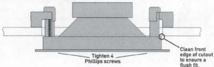
Using the proper tool cut the appropriate sized hole in the ceiling. On drywall, clean cuts can be made with a drywall saw. Make sure to clean the excess debris from the front face of the hole to ensure a flush fit.

If the cable has not yet been run, do so now that you have better access to the ceiling. Once the speaker cable has been run, pull the end of the cable out of the speaker cut-out, strip back a section of the jacket as needed, and then expose 12 " (13mm) of each conductor.
To aid in speaker performance, a fibrous material, such as fiberglass, may be placed behind the speaker. This may also help to reduce unwanted sound from being transmitted into adjoining rooms. If the ceiling space has blown or loose insulation, care must be taken to prevent the loose insulation from entering the back of the speaker. This can be accomplished by placing a batt of fiberglass insulation, fabric barrier, or bag over the back of the speaker. Placing a rigid enclosure behind the speakers can be done but the enclosure should be large enough not to degrade the performance of the speaker. Rigid enclosures of less than 0.75 cu ft (21 liters) should be stuffed with acoustic insulation such as fiberglass.
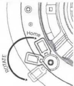
As the drawing shows, the speakers utilize Toggle Clamps which, after tightening, hold the speakers in place. Ensure that the toggle clamps are rotated into their "Home" position prior to installation.
Verify that the speaker fits properly into the cut-out and then remove the speaker from the hole.
Connect the wire conductors to the terminals on the back of the speaker by depressing each spring terminal, inserting the wire into the hole, and releasing the terminal. Use care to observe the proper polarity (+ & -). Speakers wired out of phase will exhibit an apparent loss of bass response.
Note: Dual-channel (Single-Point Stereo) speakers have both the left and right channel connections on the same speaker. Ensure that both channels are connected and in phase. An out of phase connection to a dual-channel speaker will be immediately obvious when signal is applied since there will be little if any bass output. If disconnecting one of the inputs increases the bass output then the inputs are out of phase.
Insert the speaker into the hole and tighten the four toggle screws. As you start to turn each screw the toggle clamps will rotate outward to engage the ceiling or wall material as shown. CAUTION: DO NOT OVER-TIGHTEN THE CLAMPS. Too much torque may damage the toggle, causing the speaker not to seat securely. A snug fit is all that is necessary to assure proper performance.
If your speaker includes a pivoting tweeter aiming it toward the listening area will raise the amplitude of the highest frequencies (>12kHz), adding brilliance. USE CARE TO AVOID DAMAGING THE DOME OF THE TWEETER WHEN AIMING!
The grilles can be painted using multiple light coats of spray paint. Custom color spray paints are available from specialty companies. Contact your dealer for more information. The grilles should be removed from the speaker and painted in a clean environment to prevent contamination. It is best to go around the grilles and apply the paint from multiple angles. DO NOT remove the scrim cloth from the backside of the grille. It is not replaceable.
Attach the grilles to the speakers and enjoy. Should you wish to remove the grilles from the speakers pull at the grilles' edge. Initially there will be significant resistance because the grilles are magnetically attached.
WARRANTY - LIFETIME LIMITED
AudioSource will repair or replace any product found to be faulty due to defects in material or workmanship, with new or rebuilt parts, free of charge in the USA, from the date of original purchase, for the life of the product. This is a no-hassle warranty with no mail-in warranty card needed. This warranty does not cover damages in shipment, failures caused by other products, or failures due to accident, misuse, abuse, acts of God, or alteration of the equipment. This warranty is extended only to the original purchaser, when purchased through an authorized reseller and a purchase receipt, invoice, or other proof of original purchase date is provided. This warranty gives you specific legal rights and you may have other rights (which vary by area). If a problem with this product develops during or after the warranty period, please contact AudioSource, your dealer, or any factory-authorized service center for service. Mail-in service can be obtained during the warranty period by visiting AudioSource.net. A Return Authorization (RA) number must be obtained in advance and a copy of the RA form should be included inside the shipping carton.


Brand : AudioSource
Model : AS65C
Category : Loudspeaker