
Punch Marine PM400X4 - Receiver Rockford Fosgate - Free user manual and instructions
Find the device manual for free Punch Marine PM400X4 Rockford Fosgate in PDF.


| Product Type | Marine 4-Channel Amplifier |
| Model | Punch Marine PM400X4 |
| Brand | Rockford Fosgate |
| Power Output (RMS) | 50W x 4 @ 4 ohms, 75W x 4 @ 2 ohms |
| Frequency Response | 20 Hz - 20 kHz |
| Input Sensitivity | 150 mV - 5 V |
| Amplifier Class | AB |
| Total Harmonic Distortion (THD) | < 0.05% |
| Signal-to-Noise Ratio | > 100 dB |
| Dimensions (W x H x D) | 10.5 x 2.1 x 7.5 inches |
| Weight | 5.1 lbs |
| Protection Circuitry | Thermal, Over-current, DC offset |
| Warranty | 2 Years |
| LED Indicators | Power, Input Clip, Output Clip |
| Speaker Impedance | 4 ohms (stereo), 2 ohms (stereo), 4 ohms (bridged) |
| Bridging Capability | Yes, 2 channels bridged |
| Filter Type | Low-pass, High-pass (variable) |
| Input Connections | RCA line-level inputs |
| Speaker Connections | Screw terminals |
| Power Supply Voltage | 10.5 - 16 V DC |
| Marine Rating | IPX6 (water resistant) |
| User Manual | Available in PDF from Rockford Fosgate |
Frequently Asked Questions - Punch Marine PM400X4 Rockford Fosgate
User questions about Punch Marine PM400X4 Rockford Fosgate
0 question about this device. Answer the ones you know or ask your own.
Ask a new question about this device
Download the instructions for your Receiver in PDF format for free! Find your manual Punch Marine PM400X4 - Rockford Fosgate and take your electronic device back in hand. On this page are published all the documents necessary for the use of your device. Punch Marine PM400X4 by Rockford Fosgate.
USER MANUAL Punch Marine PM400X4 Rockford Fosgate
Step 1 - Input
Input Clip Indicator Setup
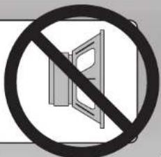
Be sure to disconnect all speakers from the amplifier

CAUTION
Failure to comply may cause damage to connected components and/or amplifier.

Step 2 - Input
Turn on the source unit with volume set to zero.


Step 3 - Input
Adjust the Bass & Treble levels on the source unit to flat.

Amplifier Clip Indicator Setup
Step 4 - Input
Insert test tone or music CD to play for setup.

Note: Use the 40Hz @ 0dB tone (Track 5) for mono amplifier applications or the 1kHz @ 0dB tone (Track 7) for multi-channel amplifier applications. Be sure your x-over is switched to the appropriate filter setting.
Step 5 - Input
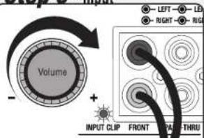
Increase the source unit volume until the Input Clip Indicator illuminates red.
Note: Input Clip can be viewed remotely with optional PLC2.
Step 6 - Input

Decrease the source unit volume slightly until the light turns completely off. This establishes your maximum source unit volume for adjusting the Output Clip Indicator.
Note: Some source units will not clip.
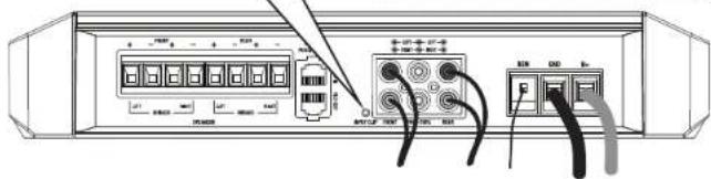
Step 7 - Output
Be sure to disconnect Punch Level Control - PLC (if equipped) from the amplifier.
Step 8 - Output
Output Clip Indicator Setup

Adjust the Input Level knob until the Output Clip Indicator illuminates to the appropriate color. Repeat for all channel levels of input.
Turn the source unit volume down.
Step 9 - Output


Step 10 - Output
Reconnect all speakers and Punch Level Control - PLC (if equipped) to the amplifier. Be sure to maintain proper speaker polarity.


Rockford Fosgate
Brand : Rockford Fosgate
Model : Punch Marine PM400X4
Category : Receiver