
ToolBox GTB-HD4K2K-441-BLK - Router Gefen - Free user manual and instructions
Find the device manual for free ToolBox GTB-HD4K2K-441-BLK Gefen in PDF.


| Product Type | 4x1 Switcher for HDMI 4K x 2K |
| Brand | Gefen |
| Model | ToolBox GTB-HD4K2K-441-BLK |
| Dimensions (W x H x D) | 6.9" x 5.8" x 1.0" (175mm x 147mm x 26mm) |
| Weight | 0.78 lbs (0.35 kg) |
| Power Input | 5V DC (locking power supply) |
| Power Consumption | 13W (max) |
| Video Inputs | 4 x HDMI Type A 19-pin female (locking) |
| Video Output | 1 x HDMI Type A 19-pin female (locking) |
| Max Resolution | Ultra HD 4K x 2K (3840x2160 @30Hz), 1080p Full HD |
| Audio Support | LPCM 7.1, Dolby TrueHD, DTS-HD Master Audio |
| Deep Color | 12-bit support (auto-disables if incompatible display detected) |
| 3DTV Pass-through | Yes |
| Lip Sync Pass-through | Yes |
| Control Methods | Front button, IR remote (channel selectable), RS-232, IP (Telnet, UDP, Web GUI) |
| RS-232 Settings | 19200 baud, 8 data bits, no parity, 1 stop bit, no flow control |
| Default IP Address | 192.168.1.72 |
| EDID Management | Built-in with advanced EDID management (lock, bank, custom modes) |
| Firmware Upgrade | Via Mini-USB or IP (web interface) |
| Safety Instructions | Read manual; keep dry; don't block vents; use dry cloth for cleaning; unplug during storms; service by qualified personnel |
| Warranty | 2 years against defects in material and workmanship (US customers) |
| Package Contents | Switcher unit, IR remote (with battery), 5V DC power supply, Quick-Start Guide |
Frequently Asked Questions - ToolBox GTB-HD4K2K-441-BLK Gefen
User questions about ToolBox GTB-HD4K2K-441-BLK Gefen
0 question about this device. Answer the ones you know or ask your own.
Ask a new question about this device
Download the instructions for your Router in PDF format for free! Find your manual ToolBox GTB-HD4K2K-441-BLK - Gefen and take your electronic device back in hand. On this page are published all the documents necessary for the use of your device. ToolBox GTB-HD4K2K-441-BLK by Gefen.
USER MANUAL ToolBox GTB-HD4K2K-441-BLK Gefen
Important Safety Instructions
GENERAL SAFETY INFORMATION
- Read these instructions.
- Keep these instructions.
- Heed all warnings.
- Follow all instructions.
- Do not use this product near water.
-
Clean only with a dry cloth.
-
Do not block any ventilation openings. Install in accordance with the manufacturer's instructions.
-
Do not install or place this product near any heat sources such as radiators, heat registers, stoves, or other apparatus (including amplifiers) that produce heat.
-
Do not defeat the safety purpose of the polarized or grounding-type plug. A polarized plug has two blades with one wider than the other. A grounding type plug has two blades and a third grounding prong. The wide blade or the third prong are provided for your safety. If the provided plug does not fit into your outlet, consult an electrician for replacement of the obsolete outlet.
-
Protect the power cord from being walked on or pinched particularly at plugs, convenience receptacles, and the point where they exit from the apparatus.
-
Only use attachments/accessories specified by the manufacturer.
-
To reduce the risk of electric shock and/or damage to this product, never handle or touch this unit or power cord if your hands are wet or damp. Do not expose this product to rain or moisture.
-
Unplug this apparatus during lightning storms or when unused for long periods of time.
-
Refer all servicing to qualified service personnel. Servicing is required when the apparatus has been damaged in any way, such as power-supply cord or plug is damaged, liquid has been spilled or objects have fallen into the apparatus, the apparatus has been exposed to rain or moisture, does not operate normally, or has been dropped.
-
Batteries that may be included with this product and/or accessories should never be exposed to open flame or excessive heat. Always dispose of used batteries according to the instructions.
Warranty Information
Gefen warrants the equipment it manufactures to be free from defects in material and workmanship.
If equipment fails because of such defects and Gefen is notified within two (2) years from the date of shipment, Gefen will, at its option, repair or replace the equipment, provided that the equipment has not been subjected to mechanical, electrical, or other abuse or modifications. Equipment that fails under conditions other than those covered will be repaired at the current price of parts and labor in effect at the time of repair. Such repairs are warranted for ninety (90) days from the day of reshipment to the Buyer.
This warranty is in lieu of all other warranties expressed or implied, including without limitation, any implied warranty or merchantability or fitness for any particular purpose, all of which are expressly disclaimed.
- Proof of sale may be required in order to claim warranty.
- Customers outside the US are responsible for shipping charges to and from Gefen.
- Copper cables are limited to a 30 day warranty and cables must be in their original condition.
The information in this manual has been carefully checked and is believed to be accurate. However, Gefen assumes no responsibility for any inaccuracies that may be contained in this manual. In no event will Gefen be liable for direct, indirect, special, incidental, or consequential damages resulting from any defect or omission in this manual, even if advised of the possibility of such damages. The technical information contained herein regarding the features and specifications is subject to change without notice.
For the latest warranty coverage information, refer to the Warranty and Return Policy under the Support section of the Gefen Web site at www.gefen.com.
PRODUCT REGISTRATION
Please register your product online by visiting the Register Product page under the Support section of the Gefen Web site.
Contacting Gefen Technical Support
Gefen, LLC
c/o Customer Service
20600 Nordhoff St.
Chatsworth, CA 91311
Telephone: (818) 772-9100
(800) 545-6900
Fax: (818) 772-9120
Email: support@gefentoolbox.com
Visit us on the Web: www.gefentoolbox.com
Technical Support Hours: 8:00 AM to 5:00 PM Monday - Friday, Pacific Time
4x1 Switcher for HDMI 4K x 2K is a trademark of Gefen, LLC.
Important Notice
Gefen, LLC reserves the right to make changes in the hardware, packaging, and any accompanying documentation without prior written notice.
HDMI, the HDMI logo, and High-Definition Multimedia Interface are trademarks or registered trademarks of HDMI Licensing in the United States and other countries.
Operating Notes
- EDID contains the A/V capabilities of a display device in regards to video resolutions and audio formats supported. This information is used by the source device to determine the format of the A/V signal on the outputs. The GefenToolBox 4x1 Switcher for HDMI 4K x 2K incorporates advanced EDID management to ensure compatibility with all sources and display devices.
- The GefenToolBox 4x1 Switcher for HDMI 4K x 2K can detect the presence of Deep Color (12-bit signal) automatically and will disable Deep Color EDID features across all other outputs if any connected device or display is not capable of processing Deep Color. This automatic behavior ensures compatibility among all output devices in a mixed-device environment. This feature cannot be disabled.
- When powering the GefenToolBox 4x1 Switcher for HDMI 4K x 2K or if the EDID mode is changed, the switcher will undergo a momentary initialization sequence. This is normal operation and may take a few seconds.
- The best way to operate and configure this unit is to use the built-in Web interface, which can be accessed by entering the IP address of the switcher into the address bar of any Web browser. See the section RS-232 and IP Configuration for more information about this feature.
Licensing
This product uses software that is subject to open source licenses, including one or more of the General Public License Version 2 and Version 2.1, Lesser General Public License Version 2.1 and Version 3, BSD, and BSD-style licenses. Distribution and use of this product is subject to the license terms and limitations of liability provided in those licenses. Specific license terms and Copyright Notifications are provided in the source code.
For three years from date of activation of this product, any party may request, and we will supply, for software covered by an applicable license (e.g. GPL or LGPL), a complete machine-readable copy of the corresponding open source code on a medium customarily used for software interchange. The following software and libraries are included with this product and subject to their respective open source licenses:
- |wIP
- jQuery
IwIP is licenced under the BSD licence:
Copyright (c) 2001-2004 Swedish Institute of Computer Science. All rights reserved.
Redistribution and use in source and binary forms, with or without modification, are permitted provided that the following conditions are met:
- Redistributions of source code must retain the above copyright notice, this list of conditions and the following disclaimer.
- Redistributions in binary form must reproduce the above copyright notice, this list of conditions and the following disclaimer in the documentation and/or other materials provided with the distribution.
- The name of the author may not be used to endorse or promote products derived from this software without specific prior written permission.
THIS SOFTWARE IS PROVIDED BY THE AUTHOR ``AS IS'' AND ANY EXPRESS OR IMPLIED WARRANTIES, INCLUDING, BUT NOT LIMITED TO, THE IMPLIED WARRANTIES OF MERCHANTABILITY AND FITNESS FOR A PARTICULAR PURPOSE ARE DISCLAIMED. IN NO EVENT SHALL THE AUTHOR BE LIABLE FOR ANY DIRECT, INDIRECT, INCIDENTAL, SPECIAL, EXEMPLARY, OR CONSEQUENTIAL DAMAGES (INCLUDING, BUT NOT LIMITED TO, PROCUREMENT OF SUBSTITUTE GOODS OR SERVICES; LOSS OF USE, DATA, OR PROFITS; OR BUSINESS INTERRUPTION) HOWEVER CAUSED AND ON ANY THEORY OF LIABILITY, WHETHER IN CONTRACT, STRICT LIABILITY, OR TORT (INCLUDING NEGLIGENCE OR OTHERWISE) ARISING IN ANY WAY OUT OF THE USE OF THIS SOFTWARE, EVEN IF ADVISED OF THE POSSIBILITY OF SUCH DAMAGE.
Features and Packing List
Features
- Switches between four Ultra Hi-Def sources to one Ultra HD display
• Supports resolutions up to Ultra HD 4K x 2K (3840 x 2160 @ 30Hz) and 1080p Full HD
• Supports 12-bit Deep Color - 3DTV pass-through
- Lip Sync pass-through
- Push button control for routing sources to display
- Supports LPCM 7.1, Dolby® TrueHD, and DTS-HD Master Audio™
- Supports the use of DVI sources and DVI displays with HDMI-to-DVI adapters (not included)
- RS-232 Serial interface for remote control using a computer or automation control system
- IP control via Telnet, UDP, and the built-in web server interface
- IR remote control
- IR Extender port allows the unit to be mounted in a hidden location
• Field-upgradeable firmware via Mini-USB and IP ports - Locking Power Supply
- Surface-mountable



HIGH-DEFINITION MULTIMEDIA INTERFACE


Packing List
The 4x1 Switcher for HDMI 4K x 2K ships with the items listed below. If any of these items are not present in your box when you first open it, immediately contact your dealer or Gefen.
• 1 x 4:1 Switcher for HDMI 4K x 2K
- 1 x IR Remote Control
• 1 x 5V DC Power Supply
- 1 x Quick-Start Guide
Table of Contents
01 Getting Started
Panel Layout 2
IR Remote Control Unit 4
Front....4
Back 5
Installing the Battery....6
Setting the IR Channel 6
Installation....7
Connecting the 4x1 Switcher for HDMI 4K x 2K 7
Sample Wiring Diagram 7
02 Operating the
4x1 Switcher for HDMI 4K x 2K
Switching Inputs 10
Using the Front Panel Buttons 10
Using the IR Remote Control 11
03 Advanced Operation
RS-232 and IP Configuration 14
RS-232 Interface 14
RS-232 Settings 14
IP / UDP Configuration.... 15
Commands....16
Configuration.... 16
IP / Telnet Configuration 35
Masking 47
Routing / Naming / +5V / Presets....49
Status 54
Web Interface 58
Using the built-in Web Server 58
Main ▶ Routing ....59
Main ▶ I/O Status....62
Main ▶ Display Info 64
I/O Setup ▶ I/O Names 65
I/O Setup ▶ HPD Control 66
I/O Setup ▶ HDCP 67
Manage EDID ▶ Assign 68
Manage EDID ▶ Bank Names .... 71
Manage EDID ▶ Upload/Download....72
Configuration ▶ Change IP Settings 74
Configuration ▶ Telnet Login Settings .... 75
Configuration ▶ UDP Connection Settings 76
Table of Contents
Configuration ▶ Web Login Settings....77
Configuration ▶ System Configuration....78
04 Appendix
Wall Mounting Instructions 84
Firmware Upgrade Procedure 85
Specifications 86
4K ULTRA HD
4x1
SOURCESDISPLAY
Switcher for HDMI
with Ultra HD
4K x 2K support
01 Getting Started
Panel Layout 2
IR Remote Control Unit 4
Front....4
Back 5
Installing the Battery....6
Setting the IR Channel 6
Installation 7
Connecting the 4x1 Switcher for HDMI 4K x 2K 7
Sample Wiring Diagram 7
Panel Layout

| ID Name Description | ||
| 1 Input Press | this button to switch between each of the four inputs on the switcher. | |
| 2 Input Indicators | Displays the currently selected input. | |
| 3 | In (1 - 4) | Connect an HDMI cable from an Ultra Hi-Def source to any of these HDMI ports. |
| 4 Out Connect | an Ultra HD display to this port using an HDMI cable. | |
| 5 Power This | LED indicator will glow bright blue when the included 5V DC power supply is connected between the switcher and an available electrical outlet. | |
| 6 RS-232 Connect | an RS-232 cable from this port to an RS-232 device. See RS-232 and IP Configuration for more information. | |
| 7 IR Ext Connect | an IR Extender (Gefen part no. EXT-RMT-IREXTN) to this port. | |
| 8 | USB | Used for upgrading the firmware. See Firmware Upgrade Procedure for more information. |
| 9 IR This IR sensor receives signals from the included IR remote control unit. | ||
| 10 IP Control | Connect an Ethernet cable between this jack and a LAN to use IP control. See RS-232 and IP Configuration for more information. | |
| 11 | 5V DC | Connect the included 5V DC power supply to this locking power receptacle. |
IR Remote Control Unit
Front
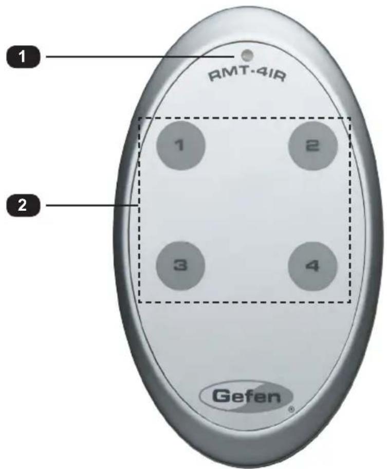
ID Name Description
1 Activity indicator This LED glows bright orange when a key is pressed on the remote.
2 1, 2, 3, 4 Press these button to switch to the desired input (source).

NOTE: An Activity indicator that flashes quickly while holding down any one of the buttons indicates a low battery. Replace the battery as soon as possible. See Installing the Battery.
Back
(shown with cover removed)

ID Name Description
| 1 DIP switch bank Use these DIP switches to set the IR channel of the remote. See Setting the IR Channel for more information. | ||
| 2 Primary battery slot (shown without battery) | Holds the battery for operating the remote. Use only 3V CR2032-type batteries. Make sure that the positive (+) side of the battery is facing up. | |
| 3 Alternate battery slot Allows for the installation of secondary (backup) battery. | ||
Installing the Battery
The IR remote control unit ships with two batteries. Only one battery is required for operation. The second battery is a spare.

WARNING: Use only 3V CR2032-type batteries. Risk of explosion if battery is replaced by an incorrect type. Dispose of used batteries according to the instructions.
- Remove the back cover the IR Remote Control unit.
- Insert the included battery into the primary battery slot. The positive (+) side of the battery should be facing up.
- Replace the back cover.
Setting the IR Channel
In order for the included IR remote control to communicate with the 4x1 Switcher for HDMI 4K x 2K, the IR remote control must be set to the same channel as the switcher. Use the #set_ir command to set the IR channel of the switcher.

| IR Channel DIP settings | |
| 0 (default) | 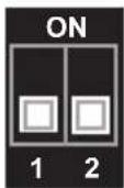 |
| 1 | 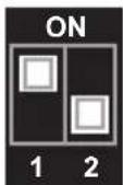 |
| 2 |  |
| 3 | 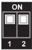 |
Connecting the 4x1 Switcher for HDMI 4K x 2K
- Connect up to four Ultra Hi-Def sources to the In (1 - 4) ports on the switcher.
- Connect an Ultra Hi-Def display to the Out port on the switcher.
- OPTIONAL: Connect an RS-232 cable from the RS-232 port on the switcher to the RS-232 connector on the serial controller (e.g. Gefen PACS, etc).
- OPTIONAL: Connect an Ethernet cable from the IP Control port on the switcher to a Local Area Network (LAN).
- OPTIONAL: Connect an IR extender to the IR Ext port on the switcher.
- Connect the included 5V DC locking power supply to the 5V DC power receptacle on the switcher. Do not overtighten the locking power connector.
- Connect the power supply to an available electrical outlet.
Sample Wiring Diagram
![graph TD A["GEFEN TOOLBOX"] --> B["Ultra HD Source"] A --> C["Ultra HD Source"] A --> D["Ultra HD Source"] A --> E["Ultra HD Source"] B --> F["TRI-16A"] C --> F D --> F E --> F F --> G["IR Extender"] G --> H["Network"] G --> I["IP Control"] G --> J["EXT-PACS"] F --> K["Ultra HD Splitter for HDMI"] K…](/content/2026/05/1084069/images/1fde8b5bc25bebcb1c3b322466b4c8d0914293ab36979d19abe80b746f1dab31.jpg)
4K ULTRA HD
4x1
SOURCESDISPLAY
Switcher for HDMI
with Ultra HD
4K x 2K support
02 Operating the
4x1 Switcher for HDMI 4K x 2K
Switching Inputs 10
Using the Front Panel Buttons 10
Using the IR Remote Control 11
Switching Inputs
Using the Front Panel Buttons
The front panel of the 4x1 Switcher for HDMI 4K x 2K has a set of four (4) LED indicators which are associated with each input on the switcher. Each input can be routed to the output. Press the Input button to cycle through each of the inputs.
- When the switcher is powered-on for the first time, Input 1 (In 1) will automatically be selected.
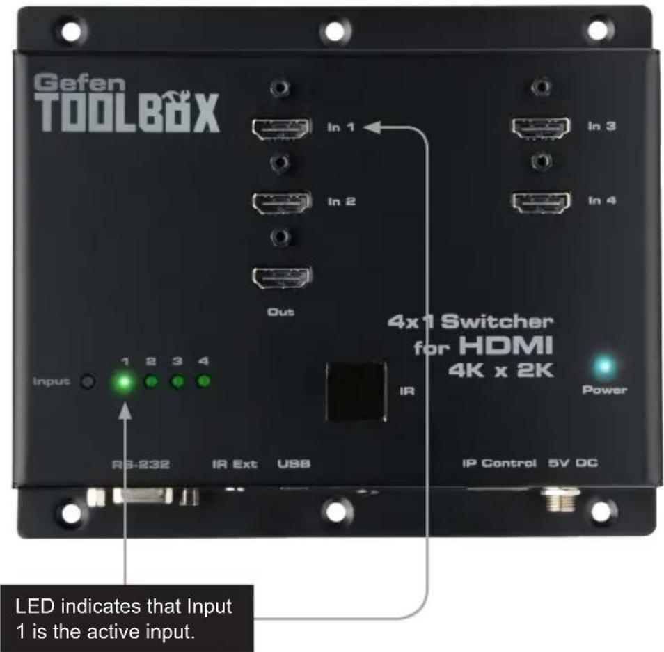
- Press the Input button to select Input 2 (In 2). Consecutively press the Input button until the desired input is selected. Once Input 4 (In 4) is selected, press the Input again to return to Input 1 (In 1).

Using the IR Remote Control
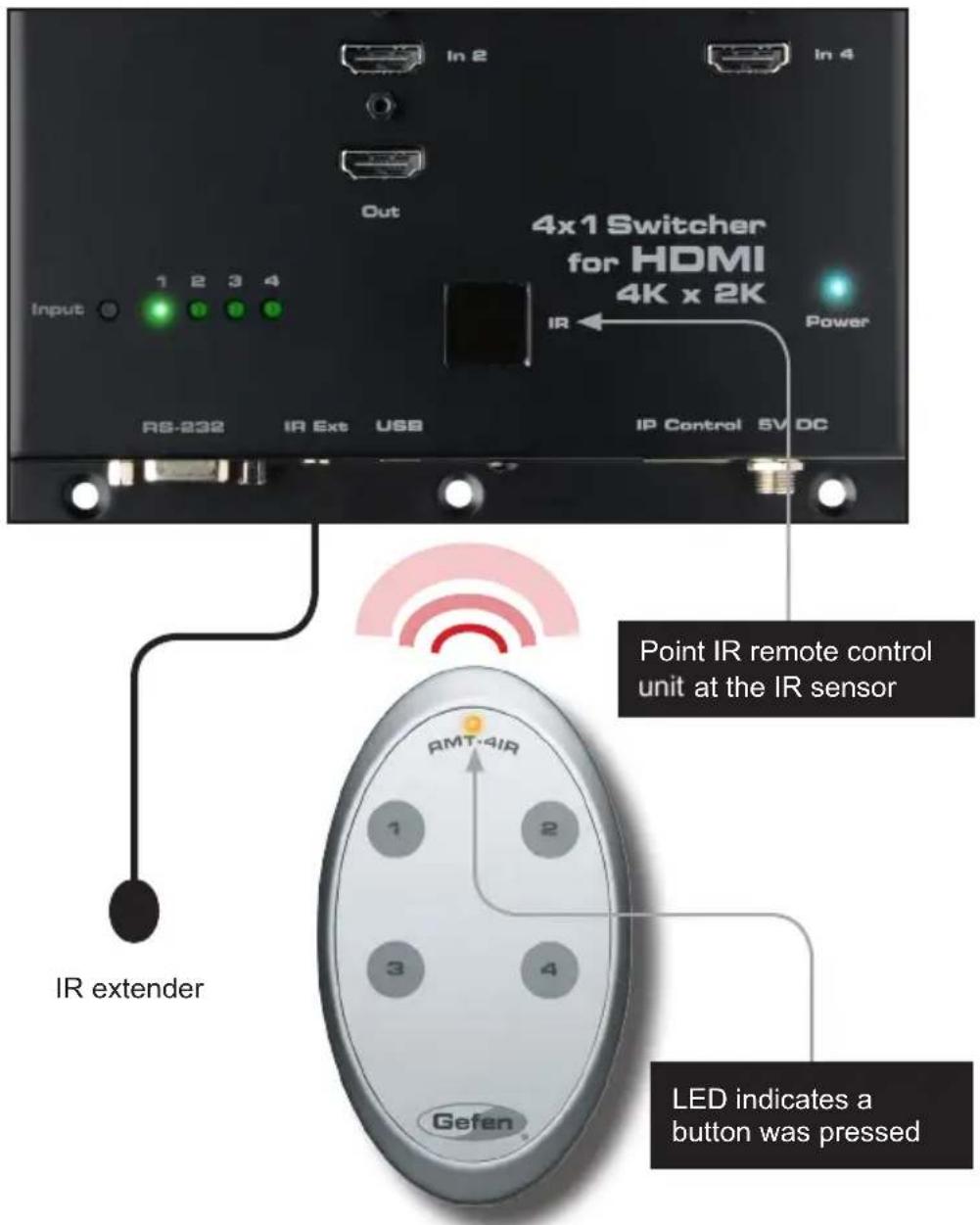
The included IR remote control unit can also be used to switch between each input. The front panel of the 4x1 Switcher for HDMI 4K x 2K has a set of four (4) LED indicators which are associated with each input on the switcher.
- When the switcher is powered-on for the first time, Input 1 (In 1) will automatically be selected.
- Point the included IR remote control unit at the IR sensor on the top panel. If an IR extender is being used, then both IR sensors will be used to receive IR signals.
- Each button on the IR remote control unit represents an input. Press the desired button on the IR remote control to switch to that input.
4K ULTRA HD
4x1
SOURCESDISPLAY
Switcher for HDMI
with Ultra HD
4K x 2K support
03 Advanced Operation
RS-232 and IP Configuration 14
RS-232 Interface 14
RS-232 Settings 14
IP / UDP Configuration....15
Commands....16
Configuration....16
IP / Telnet Configuration 35
Masking 47
Routing / Naming / +5V / Presets....49
Status....54
Web Interface 58
Using the built-in Web Server 58
Main ▶ Routing ....59
Main ▶ I/O Status....62
Main ▶ Display Info 64
I/O Setup ▶ I/O Names 65
I/O Setup ▶ HPD Control 66
I/O Setup ▶ HDCP 67
Manage EDID ▶ Assign 68
Manage EDID ▶ Bank Names .... 71
Manage EDID ▶ Upload/Download....72
Configuration ▶ Change IP Settings 74
Configuration ▶ Telnet Login Settings .... 75
Configuration ▶ UDP Connection Settings 76
Configuration ▶ Web Login Settings....77
Configuration ▶ System Configuration....78
RS-232 and IP Configuration
RS-232 Interface

RS-232 Controller Switcher
![graph LR A["DCD"] -->|1| B["1"] C["RXD"] -->|2| D["2"] E["TXD"] -->|3| F["3"] G["DTR"] -->|4| H["4"] I["GND"] -->|5| J["5"] K["DSR"] -->|6| L["6"] M["RTS"] -->|7| N["7"] O["CTS"] -->|8| P["8"] Q["R1"] -->|9| R["9"] B --> S["DCD"] D --> T["RXD"] F --> U["TXD"] J --> V["DTR"] L --> W["DSR"] N --> X["R…](/content/2026/05/1084069/images/a07f8762d2a639a800784ca40b42f44e519046c3f130ee49efb4e367c328183a.jpg)
Only TXD, RXD, and GND pins are used.
RS-232 Settings
| Description Setting | |
| Baud rate | 19200 |
| Data bits | 8 |
| Parity | None |
| Stop bits | 1 |
| Hardware flow control | None |

IMPORTANT: When sending RS-232 commands, a carriage return must be included at the end of the command. A space must be included between the command and the parameter.
IP / UDP Configuration
The 4x1 Switcher for HDMI 4K x 2K supports IP-based control using Telnet, UDP, or the built-in Web-based GUI. To set up IP control, the network settings for the 4x1 Switcher for HDMI 4K x 2K must be configured via RS-232. The default network settings for the switcher are as follows:
Description IP Address / Port Description IP Address / Port
| IP Address | 192.168.1.72 | UDP Port | 23 |
| Subnet | 255.255.255.0 | Local UDP Port | 50007 |
| Gateway | 192.168.1.254 | Remote UDP IP | 192.168.1.255 |
| HTTP Port | 80 | Remote UDP Port | 50008 |
- Connect an RS-232 cable from the PC to the 4x1 Switcher for HDMI 4K x 2K. Also make sure that an Ethernet cable is connected between the switcher and the network.
- Launch a terminal emulation program (e.g. HyperTerminal) and use the RS-232 settings listed on the previous page.

NOTE: Depending upon the network, all related IP, Telnet, and UDP settings will need to be assigned. Consult your network administrator to obtain the proper settings.
- Set the IP address for the switcher using the #sipadd command.
- Set the subnet mask using the #snetmask command.
- Set the gateway (router) IP address using the #sgateway command.
- Set the Telnet listening port using the #set_telnet_port command.
- Set the HTTP listening port using the #set_http_port command.
- Set the UDP remote IP address for the switcher using the #set_udp_remote_ip command.
- Set the UDP listening port for the switcher using the #set_udp_port command.
- Set the UDP remote port for the switcher using the #set_udp_remote_port command.
- Reboot the switcher to apply all changes, then type the IP address that was specified in step 3, in a Web browser to access the Web GUI. Use the same IP address to Telnet to the switcher.
Commands
Configuration
| Command Description | |
| #echo | Enables / disables RS-232 feedback |
| #fadefault | Resets the routing and masking to factory-default settings |
| #hdcp | Enables / disables HDCP detection |
| #hdp_pulse | Cycles with HPD line on the specified output |
| #lock_edid | Locks the local EDID when the switcher is power-cycled |
| #power | Toggles the power on the switcher |
| #reboot | Reboots the switcher |
| #set_edid | Sets the specified EDID to an input or bank |
| #set_ir | Sets the IR channel for the switcher |
| #set_udp_port | Sets the local UDP listening port |
| #set_udp_remote_ip | Sets the remote UDP IP address |
| #set_udp_remote_port | Sets the remote UDP listening port |
| #show_hdcp | Displays the HDCP status of the specified input |
| #show_ir | Displays the current IR channel of the switcher |
| #show_out_colordpt | Displays the maximum color depth supported by the display (sink) device based on the EDID |
| #show_out_res | Displays the maximum video resolution supported by the display (sink) device, based on the EDID |
| #show_udp_port | Displays the current local UDP listening port |
| #show_udp_remote_ip | Displays the current remote UDP IP address |
| #show_udp_remote_port | Displays the current remote UDP listening port |
| #use_udp_enable | Enables / disables UDP access |
| n | Displays the routing status of the output |
| s | Routes the specified input to the output |
#echo
The #echo command enables / disables (toggles) the RS-232 feedback.
Syntax:
echo param1
Parameters:
param1
Value
[0 ... 1]
| Value Description | |
| 0 | Disable feedback |
| 1 | Enable feedback |
Example:
echo 1
LOCAL ECHO IS ON
#fadefault
The #fadefault command resets the switcher to factory-default settings. Outputs are unmasked and all IP and UDP settings are reset to default settings.
Syntax:
fadefault
Parameters:
None
Example:
fadefault
SWITCHER WAS RESET TO FACTORY DEFAULTS.
RESET SWITCHER ROUTING
OUTPUT IS UNMASKED
RESET USER DEFINE NAME
RESET IP CONFIGURATIONS
RESET WEBGUI CONFIGURATIONS
SWITCHER WILL REBOOT SHORTLY *REBOOT UNIT IN 3 SECONDS
GTB-HD4K2K-441 v0.7U
#hdcp
The #hdcp command enables / disables HDCP detection on the selected input.

NOTE: Some computers will enable HDCP if an HDCP-compliant display is detected. Set param2 = 1 to force the computer to ignore detection of an HDCP-compliant display. Setting param2 = 0 does not decrypt HDCP content.
Syntax:
hdcp param1 param2
Parameters:
param1
Input
[1
param2
Value
[0
...
Value Description
| 0 | Disable |
| 1 | Enable |
Example:
hdcp 2 0
INPUT 2 HDCP IS DISABLED
hdcp 2 1
INPUT 2 HDCP IS ENABLED
#hdp_pulse
The #hpd_pulse command cycles the HPD line on the specified input. Issuing this command is identical to physically disconnecting and reconnecting the cable between the source and the switcher. If param1 = 0, then all inputs will receive the HPD pulse.
Syntax:
hpd_pulse param1
Parameters:
param1 Input [1 ... 4]
Examples:
hpd_pulse 1
HPD PULSE HAS BEEN SENT TO INPUT 1
hpd_pulse 0
HPD PULSE HAS BEEN SENT TO ALL INPUTS
#lock_edid
The #lock_edid command secures the Local EDID by disabling the automatic loading of the downstream EDID when the switcher is powered.
Syntax:
lock_edid param1
Parameters:
param1
Value
[0
...
| Value Description | |
| 0 | Disable |
| 1 | Enable |
Examples:
lock_edid 0
SWITCHER EDID IS UNLOCKED
lock_edid 1
SWITCHER EDID IS LOCKED
#power
The #power command toggles power on the switcher.
Syntax:
power param1
Parameters:
param1
Value
[0 ...
| Value Description | |
| 0 | Off |
| 1 | On |
Examples:
power 0
(switcher will power-off)
power 1
(switcher will power-on)
#reboot
The #reboot command reboots the switcher. Executing this command is the equivalent of disconnecting and reconnecting the AC power cord, on the back of the switcher.
The switcher must be rebooted after changing any of the IP settings.
Syntax:
reboot
Parameters:
None
Example:
reboot
SWITCHER WILL REBOOT SHORTLY *REBOOT UNIT IN 3 SECONDS
GTB-HD4K2K-441 v0.7U
#set_edid
The #set_edid command sets the specified EDID type to an input or bank.
Syntax:
set_edid param1 param2 param3 param4
Parameters:
param1 Source [STRING]
| Source Description | |
| default | Uses default (Internal) EDID |
| dynamic | Uses dynamic EDID |
| bank | Uses EDID bank |
| output | Uses EDID on Output (sink) |
param2 Source [0 ... 8]
| Source Description | |
| 0 | Default EDID |
| 1 ... 8 | EDID bank |
| 1 | Output |
param3 Target [STRING]
| Target Description | |
| input | Specifies an input |
| bank | Specifies an EDID bank |
param4 Target
[1] ...
| Value Description | |
| 1 ... 4 | Input |
| 1 ... 8 | EDID bank |
(continued on next page)
Notes:
If param1 = default or param1 = dynamic, then set param2 = 0.
Examples:
#set_edid default 0 input 4
COPY DEFAULT EDID TO INPUT 4
#set_edid output 1 input 3
COPY OUTPUT1 EDID TO INPUT3
#set_edid dynamic 0 input 2
COPY DYNAMIC EDID TO INPUT 2
#set_edid bank 3 input 4
COPY BANK 3 EDID TO INPUT 4
#set_ir
The #set_ir command sets the IR channel for the switcher. The default IR channel setting is 0. The IR channel for the switch can also be set under the Configuration tab within the Web interface. See Configuration ▶ System Configuration for more information.
Syntax:
set_ir param1
Parameters:
param1
Channel
[0 ...
| Channel Description | |
| 0 | Set IR channel 0 |
| 1 | Set IR channel 1 |
| 2 | Set IR channel 2 |
| 3 | Set IR channel 3 |
Example:
set_ir 1
IR CHANNEL IS SET TO CHANNEL 1
#set_udp_port
The #set_udp_port command sets the local UDP server listening port. The default port setting is 21. The switcher must be rebooted after executing this command. Use the #show_udp_port command to display the current local UDP listening port.
Syntax:
set_udp_port param1
Parameters:
param1
Port
[0
...
65535]
Example:
set_udp_port 56
UDP COMMUNICATION PORT 56 IS SET. PLEASE REBOOT THE UNIT.
#set_udp_remote_ip
The #set_udp_remote_ip command sets the remote UDP IP address. The IP address must be specified using dot-decimal notation. The default UDP remote IP address is 192.168.1.255. The switcher must be rebooted after executing this command.
Syntax:
set_udp_remote_ip param1
Parameters:
param1 UDP address
Example:
set_udp_remote_ip 192.168.1.227
REMOTE UDP IP ADDRESS 192.168.1.227 IS SET.
#set_udp_remote_port
The #set_udp_remote_port command sets the remote UDP listening port. The default remote UDP listening port is 50008. The switcher must be rebooted after executing this command.
Syntax:
set_udp_remote_port param1
Parameters:
param1 Port
[0 ... 65535]
Example:
set_udp_remote_port 50008
REMOTE UDP COMMUNICATION PORT 50008 IS SET.
#show_hdcp
The #show_hdcp command displays the HDCP status on the specified input.
Syntax:
show_hdcp param1
Parameters:
param1
Input
[1] ...
Example:
show_hdcp 1
INPUT 1 HDCP IS ENABLED
#show_ir
The #show_ir command displays the IR channel of the switcher.
Syntax:
show_ir
Parameters:
None
Example:
show_ir
CURRENT IR CHANNEL IS: 0
#show_out_colordpt
The #show_out_colordpt command displays the highest color depth supported by the specified display based on the EDID. If no display is attached to the specified output, then the command will return NO SIGNAL.
Syntax:
#show_out_colordpt
Parameters:
None
Example:
#show_out_colordpt
OUTPUT HIGHEST COLOR DEPTH IS 8 BITS
#show_out_res
The #show_out_res command displays the highest resolution supported by the specified display based on the EDID. If no display is attached to the specified output, then the command will return NO SIGNAL.
Syntax:
#show_out_res
Parameters:
None
Example:
#show out res
OUTPUT HIGHEST RESOLUTION IS 1600x900
#show_udp_port
The #show_udp_port command displays the current local UDP listening port. Use the #set_udp_port command to set the local UDP listening port.
Syntax:
#show_udp_port
Parameters:
None
Example:
#show_udp_port
UDP COMMUNICATION PORT IS 56
#show_udp_remote_ip
The #show_udp_remote_ip command displays the remote UDP IP address. Use the #set_udp_remote_ip command to set the remote UDP IP address.
Syntax:
set_udp_remote_ip param1
Parameters:
None
Example:
#set_udp_remote_ip 192.168.1.227
REMOTE UDP IP ADDRESS IS : 192.168.1.227
#show_udp_remote_port
The #show_udp_remote_port command displays the remote UDP listening port. Use the #set_udp_remote_port to set the remote UDP listening port.
Syntax:
set_udp_rport param1
Parameters:
None
Example:
show_udp_remote_port
REMOTE UDP COMMUNICATION PORT IS 50008
#use_udp_enable
The #use_udp_enable command enables or disables UDP access mode.
Syntax:
use_udp_enable param1
Parameters:
param1 Value
[0 ... 1]
| Value Description | |
| 0 | Disable UDP |
| 1 | Enable UDP |
Example:
use_udp_enable 1
UDP ACCESS IS ENABLED
n
The n command displays the routing status of the output. Do not precede the n command with the “#” symbol. param1 must be set to 1.
Syntax:
n param1
Parameters:
param1
Constant
1
Examples:
To see how this command works, we have already selected Input 3 on the switcher. Now, we'll use the n command to query the output:
n 1
A3
The feedback is abbreviated as: "A3". This indicates that Input 3 is the active input.
s
The s command routes the specified input to the output. Do not precede this command with the “#” symbol.
Syntax:
s param1
Parameters:
param1
Input
[1
...
Example:
s 2
INPUT 2 IS ROUTED TO OUTPUT
IP / Telnet Configuration
| Command Description | |
| #display_telnet_welcome | Enable / disable the Telnet welcome message |
| #ipconfig | Displays the current IP configuration |
| #resetip | Resets the IP configuration to factory-default settings |
| #set_http_port | Sets the Web server listening port |
| #set_telnet_pass | Sets the Telnet password |
| #set_telnet_pass | Sets the Telnet listening port for the switcher |
| #set_webui_ad_pass | Sets the Administrator password for the Web GUI |
| #set_webui_op_pass | Sets the Operator password for the Web GUI |
| #sgateway | Sets the IP address of the (router) gateway |
| #show_gateway | Displays the current gateway address of the switcher |
| #show_http_port | Displays the current HTTP listening port of the switcher |
| #show_ip | Displays the current IP address of the switcher |
| #show_mac_addr | Displays the MAC address of the switcher |
| #show_netmask | Displays the current net mask of the switcher |
| #show_telnet_port | Displays the Telnet listening port |
| #sipadd | Sets the IP address of the switcher |
| #snetmask | Sets the Net mask of the switcher |
| #use_telnet_pass | Force password during Telnet sessions |
#display_telnet_welcome
The #display_telnet_welcome command enables / disables the Telnet welcome message during a Telnet session.
Syntax:
display_telnet_welcome
Parameters:
param1
Value
[0 ... 1]
| Value Description | |
| 0 | Disable welcome message |
| 1 | Enable welcome message |
Example:
display_telnet_welcome 1
TELNET WELCOME SCREEN IS ENABLED
When enabled and a Telnet session has been started, the following will appear:
Welcome to GTB-HD4K2K-441 TELNET
telnet->
#ipconfig
The #ipconfig command displays the current TCP settings.
Syntax:
ipconfig
Parameters:
None
Example:
ipconfig
IP Configuration is :
IP: 192.168.2.190
NETMASK: 255.255.255.0
GATEWAY: 192.168.1.254
#resetip
The #resetip command resets the IP configuration to factory-default settings. The switcher must be rebooted after executing this command.
Syntax:
resetip
Parameters:
None
Syntax:
resetip
IP CONFIGURATION WAS RESET TO FACTORY DEFAULTS
IP: 192.168.1.72
Netmask: 255.255.255.0
Gateway: 192.168.1.1
#set_http_port
The #set_http_port command specifies the Web server listening port. The switcher must be rebooted after executing this command. The default port setting is 80. Use the #show_http_port command to display the current HTTP listening port.
Syntax:
set_http_port param1
Parameters:
param1
Port
[1
...
1024]
Example:
set_http_port 82
HTTP COMMUNICATION PORT 82 IS SET. PLEASE REBOOT THE UNIT.
#set_telnet_pass
The #set_telnet_pass command sets the Telnet password. The password is case-sensitive and cannot exceed 8 characters in length. The default password is Admin.
Syntax:
set_telnet_pass param1
Parameters:
param1
Password
Example:
set_telnet_pass 3ver3st
TELNET INTERFACE PASSWORD IS SET
#set_telnet_port
The #set_telnet_port command sets the Telnet listening port. The switcher must be rebooted after executing this command. The default port setting is 23. Use the #show_telnet_port command to display the current Telnet listening port.
Syntax:
#set_telnet_port param1
Parameters:
param1
Port
[1
...
1024]
Example:
#set_telnet_port 24
TELNET COMMUNICATION PORT 24 IS SET. PLEASE REBOOT THE UNIT.
#set_webui_ad_pass
The #set_webui_ad_pass command sets the Administrator password for the Web GUI. The password is case-sensitive and cannot exceed 7 characters in length. The default password is Admin.
Syntax:
#set_webui_ad_pass param1
Parameters:
param1
Password
Example:
#set_webui_ad_pass bossman
WEB UI ADMINISTRATOR PASSWORD IS SET
#set_webui_op_pass
The #set_webui_ad_pass command sets the Operator password for the Web GUI. The default password is Admin.
Syntax:
set_webui_op_pass param1
Parameters:
param1
Password
Example:
set_webui_op_pass minion
The #sgateway command sets the gateway address. The gateway must be typed using dot-decimal notation. The switcher must be rebooted after executing this command. The default gateway is 192.168.1.1.
Syntax:
sgateway param1
Parameters:
param1
Gateway
Example:
sgateway 192.168.1.5
GATEWAY ADDRESS 192.168.1.5 IS SET. PLEASE REBOOT THE UNIT.
#show_gateway
The #show_gateway command displays the current gateway address of the switcher. Use the #sgateway command to set the gateway address.
Syntax:
#show_gateway
Parameters:
None
Example:
#show_gateway
GATEWAY ADDRESS IS: 192.168.1.5
#show_http_port
The #show_http_port command displays the current HTTP listening port of the switcher. Use the #set_http_port command to set the HTTP listening port.
Syntax:
#show_http_port
Parameters:
None
Example:
#show_http_port
HTTP COMMUNICATION PORT IS: 82
#show_ip
The #show_ip command displays the current IP address of the switcher. Use the #sipadd command to set the IP address.
Syntax:
#show_ip
Parameters:
None
Example:
#show_ip
IP ADDRESS IS: 192.168.1.239
#show_mac_addr
The #show_mac_addr command displays the MAC address of the switcher.
Syntax:
#show_mac_addr
Parameters:
None
Example:
#show_mac_addr
MAC ADDRESS IS: 00-1c-91-03-00-02
#show_netmask
The #show_netmask command displays the current net mask of the switcher. Use the #snetmask command to set the net mask.
Syntax:
#show_netmask
Parameters:
None
Example:
#show_netmask
NETMASK ADDRESS IS: 255.255.255.0
#show_telnet_port
The #show_telnet_port command displays the current Telnet port of the switcher. Use the #set_telnet_port command to set the Telnet listening port.
Syntax:
#set_telnet_port param1
Parameters:
param1
Port
[1
...
65535]
Example:
#set_telnet_port 24
TELNET COMMUNICATION PORT 24 IS SET. PLEASE REBOOT THE UNIT.
#show_telnet_username
The #show_telnet_username command displays the user name of the current Telnet session.
Syntax:
#show_telnet_username
Parameters:
None
Example:
#show_telnet_username
USER NAME FOR TELNET IS : Admin
#show_ver_data
The #show_ver_data command displays the current software and hardware version.
Syntax:
#show_ver_data
Parameters:
None
Example:
#show_ver_data
SOFTWARE AND HARDWARE VERSION : v0.7U PCB-1979*B
#sipadd
The #sipadd command sets the IP address of the switcher. The IP address must be entered using dot-decimal notation. The switcher must be rebooted after executing this command. The default IP address is 192.168.1.72. Use the #show_ip or #ipconfig command to display the current IP address of the switcher.
Syntax:
sipadd param1
Parameters:
param1 IP address
Example:
sipadd 192.168.2.190
IP ADDRESS 192.168.2.190 IS SET.
#snetmask
The #snetmask command sets the subnet mask. The net mask must be entered using dot-decimal notation. The switcher must be rebooted after executing this command. The default net mask is 255.255.255.0. Use the #show_netmask or #ipconfig command to display the current net mask of the switcher.
Syntax:
snetmask param1
Parameters:
param1 Net mask
Example:
snetmask 255.255.0.0
NETMASK ADDRESS 255.255.0.0 IS SET. PLEASE REBOOT THE UNIT.
#use_telnet_pass
The #use_telnet_pass command forces the password credentials for each Telnet session. The default setting is 0 (disabled). Use the #set_telnet_pass command to set the Telnet password.
Syntax:
use_telnet_pass param1
Parameters:
param1
Value
[0 ... 1]
| Value Description | |
| 0 | Disable password |
| 1 | Enable password |
Example:
use_telnet_pass 1
TELNET INTERFACE PASSWORD IS ENABLED
Masking
| Command Description | |
| #mask | Masks the video on the specified output(s) |
| #show_mask | Displays the current masking status of each output |
| #unmask | Unmasks the specified outputs |
#mask
The #mask command masks the video on the output. Use the #unmask command to disable output masking.
Syntax:
mask
Parameters:
None
Example:
mask
OUTPUT IS MASKED
#unmask
The #unmask command unmasks the output. Use the #mask command to mask the output.
Syntax:
unmask
Parameters:
None
Example:
unmask
OUTPUT IS UNMASKED
#show_mask
The #show_mask command displays the mask status of the output.
Syntax:
show_mask
Parameters:
None
Example:
show_mask
OUTPUT(OUTPUT1) IS UNMASKED
Routing / Naming / +5V / Presets
Command Description
| #lock_switcher | Locks / unlocks the switcher |
| #set_bank_name | Assigns an EDID bank with the specified name |
| #set_input_name | Assigns an input with the specified name |
| #set_output_name | Assigns the output with the specified name |
| #show_bank_name | Displays the name for the specified EDID bank |
| #show_input_name | Displays the name of the specified input |
| #show_output_name | Displays the name of the output |
| #show_r | Displays the routing status of the output |
| r | Routes the specified input to the output |
#lock_switcher
The #lock_switcher command locks / unlocks the switcher. When the switcher is locked, all functions are disabled including the front panel, RS-232, and Telnet.
Syntax:
lock_switcher param1
Parameters:
param1
Value
[0 ...
| Value Description | |
| 0 | Unlock |
| 1 | Lock |
Example:
lock_switcher 1
SWITCHER IS UNLOCKED
#set_bank_name
The #set_bank_name command names the specified bank.
Syntax:
set_bank_name param1 param2
Parameters:
| param1 | Bank | [1 | ... | 8] |
| param2 | Name |
Example:
set_bank_name 5 Dell_24
Dell_24 NAME IS ASSIGNED TO BANK 5
#set_input_name
The #set_input_name command assigns a name to the specified input on the switcher.
Syntax:
set_input_name param1 param2
Parameters:
| param1 | Input | [1 | ... | 4] |
| param2 | Name |
Example:
set_input_name 3 Blu-ray
Blu-ray NAME IS ASSIGNED TO INPUT 3
#set_output_name
The #set_output_name command assigns a name to the output on the switcher. The name of the output cannot exceed 15 characters in length. Names longer than 15 characters will be truncated. To name an output, use the #set_output_name command.
Syntax:
set_output_name param1
Parameters:
param1 Name [STRING]
Example:
set_output_name 3 Sony_XBR
Sony_XBR NAME IS ASSIGNED TO OUTPUT
#show_bank_name
The #show_bank_name command displays the name for the specified EDID bank. To name an EDID bank, use the #set_bank_name command.
Syntax:
show_bank_name param1
Parameters:
param1 Bank [1 ... 8]
Example:
show_bank_name 5
THE NAME FOR BANK 5 IS : Dell_24
#show_input_name
The #show_input_name command displays the name of the specified input. To name an input, use the #set_input_name command.
Syntax:
show_input_name param1
Parameters:
param1 Input [1 ... 4]
Example:
show_input_name 3
THE NAME FOR INPUT 3 IS : Blu-ray
#show_output_name
The #show_output_name command displays the name of the output. To name an output, use the #set_output_name command.
Syntax:
show_output_name
Parameters:
None
Example:
show_output_name
THE NAME FOR OUTPUT IS : Sony_XBR
#show_r
The #show_r command displays the current routing status of the output. The name of the output and input are displayed.
Syntax:
#show_r
Parameters:
None
Example:
#show_r
OUTPUT(Sony_XBR) IS ROUTED TO INPUT 1(INPUT1)
r
The r command routes the specified input to the output. Do not precede this command with the “#” symbol. Also see the s command.
Syntax:
r param1
Parameters:
param1
Input
[1 ...
Example:
r 3
INPUT 3 IS ROUTED TO OUTPUT
Status
Command Description
| #help | Displays a list of available RS-232 / Telnet commands |
| #show_fw | Displays the current version of firmware |
| #show_hpd | Displays the HPD status of the specified input |
| #show_rsense | Displays the RSENSE status of the output |
| m | Displays the current routing status of the switcher |
#help
The #help command displays the list of available RS-232 / Telnet commands. Help on a specific command can be displayed when using param1.
Syntax:
help param1
Parameters:
param1 Command name (optional)
Example:
help #sipadd
SIPADD PARAM 1
SET THE IP ADDRESS
PARAM 1 = XXX.XXX.XXX.XXX
WHERE XXX: 0 - 255
#show_fw
The #show_fw command displays the current version of switcher firmware.
Syntax:
#show_fw
Parameters:
None
Example:
#show_fw
FIRMWARE VERSION = GTB-HD4K2K-441 v0.7U
#show_hpd
The #show_hpd command displays the HPD status of the specified output. The name of the output is included.
Syntax:
#show_hpd
Parameters:
None
Example:
#show_hpd
HPD OF OUTPUT (Sony_XBR) IS HIGH
#show_rsense
The #show_rsense command displays the RSENSE status of the output. The name of the output is included.
Syntax:
#show_rsense
Parameters:
None
Example:
#show_rsense
RSENSE OF OUTPUT 6 (Output6) IS HIGH
m
The m command displays the current routing status of the switcher. Do not precede the m command with the “#” symbol.
Syntax:
m
Parameters:
None
Example:
m
Out : 1
In : 2
OUTPUT 1 IS UNMASKED
SWITCHER IS UNLOCKED
Web Interface
Using the built-in Web Server
Access the built-in Web interface by entering the IP address of the switcher that was specified in step 3 under IP / UDP Configuration. Once connected to the switcher, the login screen will be displayed.
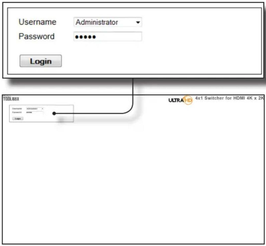
Username
Select the username from the drop-down list.
Options:
Operator, Administrator
Administrator login provides unrestricted access to all features and settings.
Operator login limits access to switcher routing, display information, and routing preset features.
Password
Enter the password for the associated username. The password can also be set using RS-232 or Telnet. See the #set_webui_op_pass and the #set_webui_ad_pass commands. The password is masked when it is entered.
The Web GUI is divided into four main pages: Main, I/O Setup, Manage EDID, and Configuration. Each main page is represented by a tab at the top-most portion of the screen. The Main, I/O Setup, and Manage EDID pages have their own set of sub-tabs. Click on the desired tab / sub-tab to open the desired page.

NOTE: In order to view all four tabs at the top of the screen, the user must be logged in as "Administrator". If logged-in as "Operator", only the Main tab will be visible.
Main □ Routing
Log Out
Click Log Out to terminate the current Web session are return to the login page.
Log Out
![graph TD A["Status"] --> B["Output"] A --> C["Input #"] B --> D["1"] C --> E["1"] style A fill:#f9f,stroke:#333 style B fill:#ccf,stroke:#333 style C fill:#cfc,stroke:#333](/content/2026/05/1084069/images/4532c362a0a318013888e1d9a2e885a1e70f58c55508b25d115296fc0cd05632.jpg)
Output
The number of outputs that are available for routing. Since this is a 4x1 switcher, only one output is available.
Input #
The input that is currently routed to the output.
![graph TD A["Inputs"] --> B["Outputs"] B --> C["Name"] B --> D["OUTPUT"] B --> E["OUTPUT1"] B --> F["1"] B --> G["0"] B --> H["0"] B --> I["0"] B --> J["0"] B --> K["0"] B --> L["0"] B --> M["0"] B --> N["0"] B --> O["0"] B --> P["0"] B --> Q["0"] B --> R["0"] B --> S["0"] B --> T["0"] B --> U["0"] B…](/content/2026/05/1084069/images/8ad7b456c8290884313c8d4796474e186900e0ab0faa9af4cb353141b528c4b2.jpg)
Name (Outputs)
The name of the output.
This name can be changed using the #set_output_name command or through the I/O Setup ▶ I/O Names page of the Web interface.
Output
Check to select the currently active output. Since only one output is available, this output is always checked.
Input # (Inputs)
Click the radio button next to the desired input to be routed. Only one input can be selected at a time.
Name (Inputs)
Displays the current name of the input.
Route
Click the Route button to route the selected input to the select output(s).
Lock Switcher
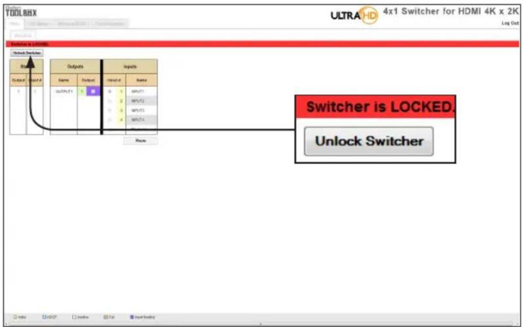
Locks / unlocks the switcher. Once the switcher is locked, settings cannot be changed using the front-panel buttons or through the Web GUI. When the switcher is locked, the button text will read "Unlock Switcher" and a red bar will appear across the top portion of the screen with the text "Switcher is LOCKED". Click the "Unlock Switcher" button to unlock the switcher.

Main □ I/O Status

Output
Displays the state of each output for each of the following: Name, RSENSE, Mask, HPD (Hot-Plug Detect), HDCP, and Video Mode.
Name
Displays the name of the output. The name of the output can be changed using the #set_output_name command or through the I/O Setup ▶ I/O Names page of the Web interface.
RSENSE
Displays the current Rsense state.
Mask
Displays the masking state of each output.
HPD
Displays the Hot-Plug Detect (HPD) state of each output.
HDCP
Indicates if HDCP-detection is enabled or disabled on each output.
Video Mode
Displays the current output video mode.

Input
Displays the state of each input for each of the following: Input name, Color Depth, Color Space, HDCP, 3D, Active Signal, Vertical Resolution, Horizontal Resolution, Progressive / Interlaced, Refresh Rate, and Video Mode.
Main □ Display Info

Choose EDID
Select the EDID from the drop-down list. The selected EDID will be copied from the Output or selected EDID Bank to the desired input(s) and used by the source.
| Options |
| Default EDID |
| Bank 1 ... Bank 8 |
| Output 1 |
Feature / Audio Formats
Displays the capabilities of the display (or sink device), based on the EDID.
I/O Setup □ I/O Names


Output
The number of the output.
Input #
The number of each input.
Name
Type the desired name of the output and/or input(s) in these fields.
Save Changes
Saves the current changes to the name of the output and/or input(s).
Cancel
Restores the previous name or each output and/or input(s), if a change was made.
I/O Setup □ HPD Control
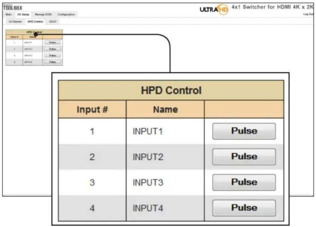
Input #
The number of the input.
Name
The name of the input. The name of each input can be changed using the #set_input_name command or through the I/O Setup ▶ I/O Names page of the Web interface.
Pulse
Click the Pulse button to cycle the HPD line on the desired input. This is the equivalent of physically disconnecting and reconnecting the HDMI cable between the source device and the switcher.
I/O Setup □ HDCP

NOTE: Some computers will enable HDCP if an HDCP-compliant display is detected. Check the box under the Disable column to force the computer to ignore detection of an HDCP-compliant display. The Disable feature does not decrypt HDCP content.

Disable
Check the box under the Disable column to force the computer to ignore HDCP-detection.
Input #
The number of the input.
Name
The name of the input. The name of each input can be changed using the #set_input_name command or through the I/O Setup ▶ I/O Names page of the Web interface.
Check All
Places a check mark in all boxes under the Disable column.
Clear All
Clears all check marks from the Disable column.
Set
Click this button to save changes for all input(s).
Cancel
Cancels the current operation and ignores changes for each input, if a change was made.
Manage EDID □ Assign
Lock EDID
Secures the Local EDID and disables automatic EDID loading during power-up.
If the Lock EDID button is clicked (enabled), the "EDID locked on power cycle" message will be displayed in red. The local EDID information will now be locked once the switcher is rebooted. Click the Unlock EDID button to disable the Lock EDID feature.

Copy EDID From
Select the EDID from the drop-down list. The EDID will be copied from the Output or selected EDID bank to the destination
| Options |
| Bank 1 ... Bank 8 |
| Output 1 |
| Inputs | |||||
| Copy To | EDID Modes | Input # | Name | EDID Source | EDID Name |
| External - Output1▼ | 1 | INPUT1 | Ext EDID(OUT1) | DELL E2010H | |
| External - Output1▼ | 2 | INPUT2 | Ext EDID(OUT1) | DELL E2010H | |
| External - Output1▼ | 3 | INPUT3 | Ext EDID(OUT1) | DELL E2010H | |
| External - Output1▼ | 4 | INPUT4 | Ext EDID(OUT1) | DELL E2010H | |

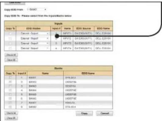
Copy To
Place a check mark in the desired check box to select or deselect the desired input(s). These check-boxes can only be used when the EDID Mode is set to Custom - User.
EDID Modes
Select the EDID mode from the drop-down list.
| Options |
| Internal - 1080p 2 ch audio |
| Internal - 1080p Multi ch |
| External - Output1 |
| Custom - Last Output* |
| Custom - User |
*Since this is a 4x1 switcher, only one output is available.
(continued on next page)
| Inputs | |||||
| Copy To | EDID Modes | Input # | Name | EDID Source | EDID Name |
| External - Output1▼ | 1 | INPUT1 | Ext EDID(OUT1) | DELL E2010H | |
| External - Output1▼ | 2 | INPUT2 | Ext EDID(OUT1) | DELL E2010H | |
| External - Output1▼ | 3 | INPUT3 | Ext EDID(OUT1) | DELL E2010H | |
| External - Output1▼ | 4 | INPUT4 | Ext EDID(OUT1) | DELL E2010H | |
Input #
The number of the input.
Name
The name of the input. The name of the input can be changed using the #set_input_name command or through the I/O Setup ▶ I/O Names page of the Web interface.
EDID Source
The current EDID source being used.
EDID Name
The name of the EDID.
Clear All
Clears all check marks from the Copy To column.
Manage EDID □ Bank Names

Bank #
Indicates the EDID bank number.
Name
Type the desired name of the EDID bank in this field.
Save Changes
Saves the current name change to the EDID bank(s).
Cancel
Restores the previous names for each EDID bank, if a change was made.
Manage EDID □ Upload/Download
Browse...
Click this button to select the EDID file to be uploaded.
Select Bank Location
Click this drop-down list to select the bank to where the EDID will be uploaded.
Options
1 - Bank1 ... 8 - Bank8
Upload
Click this button to upload the EDID to the specified bank.
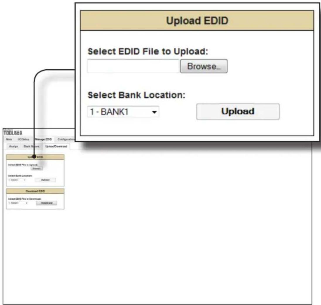

Select EDID File to Download
Click this box to select the EDID that is to be saved to a file. The EDID file will be saved in binary (.bin) format.
| Options |
| 1 - BANK1 ... 8 - BANK8 |
| 1 - OUTPUT1 |
| 1 - INPUT1 ... 4 - INPUT4 |
Download
Click this button to download the selected EDID to a file.
Configuration □ Change IP Settings

Change IP Settings
Assigns the IP address, subnet, gateway, HTTP listening port, Telnet port, and UDP port. The MAC address cannot be changed.
Save Settings
Saves the current settings for the Change IP Settings. After clicking this button, the Web interface will display a dialog indicating that the switcher must be rebooted for changes to take effect.
Set Defaults
Click this button to restore the factory-default IP settings. After clicking this button, the Web interface will display a dialog indicating that the switcher must be rebooted for changes to take effect.
Configuration □ Telnet Login Settings


Old Password
Type the current (old) password in this field.
New Password
Type the new password in this field.
Force Password on Connect
Click this check box to have the switcher prompt for a password each time a Telnet session is started. This box must be checked in order to change the Telnet Login credentials.
Show Login Message on Connect
Click this check box to have the switcher display the Telnet welcome message each time a Telnet session is started. The welcome message appears as:
"Welcome to GTB-HD4K2K-441 TELNET".
Save Settings
Saves the current changes to the Telnet Login Settings.
Configuration □ UDP Connection Settings

UDP Connection Settings
Remote UDP IP Address:
192.168.1.80
Remote UDP Port:
50010
Enable UDP Access:
√
Save Settings
Remote UDP IP Address
Type the remote UDP IP address in this text box.
Remote UDP Port
Enter the remote UDP port in this text box.
Enable UDP Access
Check this box to enable UDP access. If this box is unchecked, the UDP access will be unavailable.
Configuration □ Web Login Settings
Web Login Settings
Username:
Operator
Old Password:

New Password:
Confirm New Password:
Save Settings

Username
Click this drop-down list to select the username to be changed.
Old Password
Type the current (old) password in this field.
New Password
Type the new password in this field.
Confirm Password
Re-type the new password in this field.
Save Settings
Saves the current changes to the Web Login Settings.
Configuration □ System Configuration

Download
Click this button to download the current switcher configuration to a file.
(continued on next page)
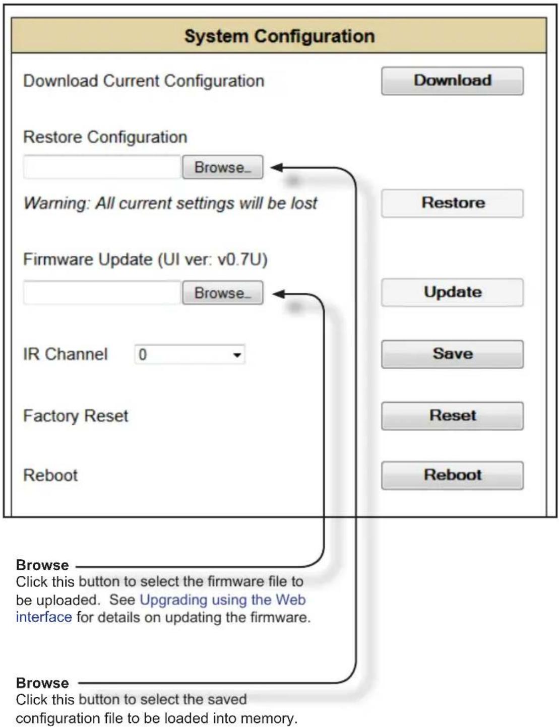
Restore
Uploads the selected configuration file to the switcher.
Update
Updates the switcher with the selected firmware file.
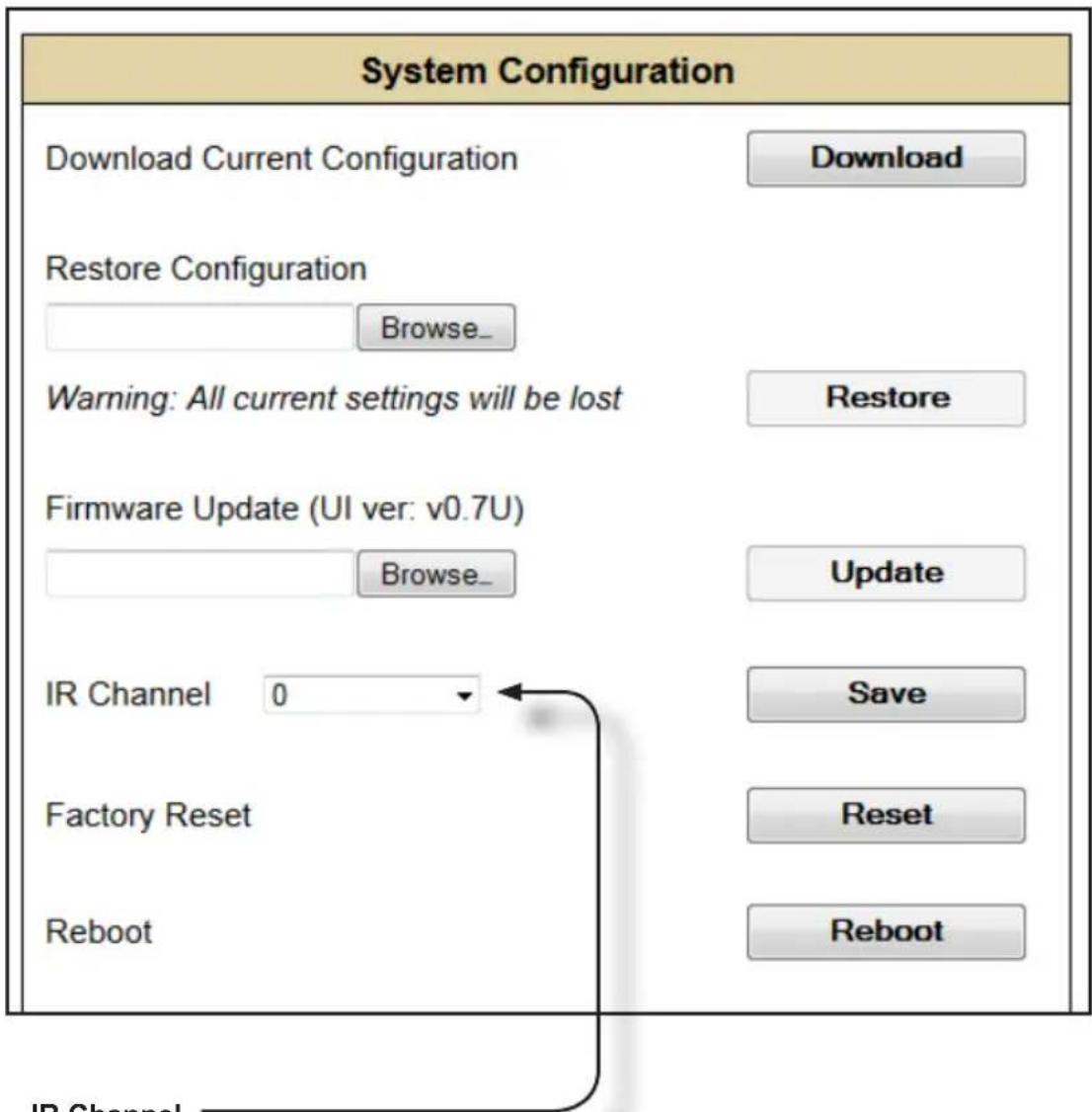
IR Channel
Click this drop-down list to set the desired IR channel for the switcher. Note that the switcher and the included IR remote control must be set to the same channel in order to work properly. The IR channel for the switcher can also be set using the #set_ir command.
Options
0 ... 3
Save
Click this button to save any changes made to the IR channel setting.
Reset
Click this button to set the switcher to factory-default settings. The IP settings are preserved.
Reboot
Click this button to reboot the switcher.
4K ULTRA HD
4x1
SOURCESDISPLAY
Switcher for HDMI
with Ultra HD
4K x 2K support
04 Appendix
Wall Mounting Instructions 84
Firmware Upgrade Procedure 85
Specifications 86
Wall Mounting Instructions
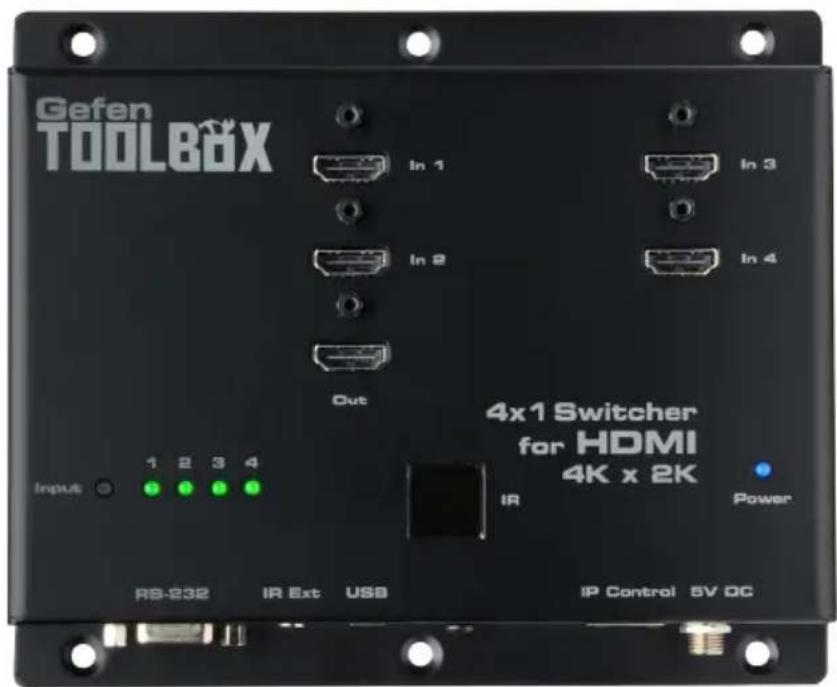
The 4x1 Switcher for HDMI 4K x 2K should be mounted vertically in a wall or cabinet with wood/drywall screws as shown in the diagram above. There should be an inch or two of clearance between the edges of the unit and any walls or vertical surfaces to allow for enough clearance for insertion and retraction of cables at the HDMI connectors.
For installation on a drywall surface, use a #6 drywall screw. It is recommended when installing on a drywall surface that studs be used to secure the switcher should undue stress be applied when connecting and disconnecting HDMI cables.

Firmware Upgrade Procedure
The following items are required to update firmware:
• GefenToolBox 4x1 Switcher for HDMI 4K x 2K
- Computer (Mac or PC)
- USB-to-Mini-USB cable
- Firmware file
- Download the firmware from the Gefen Web site.
- Extract the firmware file from the .ZIP file.
It is unnecessary to disconnect any HDMI cables from the switcher during the update process. - Connect the USB cable between the computer and the 4x1 Switcher for HDMI 4K x 2K.
- Power-ON the 4x1 Switcher for HDMI 4K x 2K.
- Once the computer is able to connect to the 4x1 Switcher for HDMI 4K x 2K, a removable disk icon will be displayed.
- Drag the .bin file to the removable disk.
- Wait for the file to be copied to the removable disk.
- After the file has been copied, disconnect the USB cable from the switcher.
- The switcher will begin updating the firmware.
- Once the firmware update has completed, the 4x1 Switcher for HDMI 4K x 2K will automatically reboot.
Specifications
| Supported Formats | |
| Resolutions (max.) • Ultra HD 4K x 2K | (3840 x 2160 @ 30 Hz)• 1080p Full HD |
| Audio • LPCM 7.1 | • Dolby® TrueHD• DTS-HD Master AudioTM |
| Electrical | |
| Maximum Pixel Clock • 300 MHz | |
| Power Indicator • 1 x LED, blue | |
| Input Indicators • 4 x LED, green | |
| Input Switch • 1 x Tact-type | |
| Connectors | |
| Video Input • 4 x HDMI, Type A 19-pin, female, locking | |
| Video Output • 1 x HDMI, Type A 19-pin, female, locking | |
| USB • Mini-B | |
| Power • Locking-type | |
| RS-232 • 1 x DB-9, female | |
| Ethernet • 1 x RJ-45 | |
| IR Extender • 1 x 3.5mm mini-stereo | |
| Operational | |
| Power Input | • 5V DC |
| Power Consumption | • 13W (max.) |
| Operating Temperature | • +32 to 104 °F (0 to +40 °C) |
| Physical | |
| Dimensions (W x H x D) | • 6.9" x 5.8" x 1.0"(175mm x 147mm x 26mm) |
| Unit Weight • 0.78 lbs (0.35 kg) | |

Stretch it, Switch it, Split it.
Gefen's got it. ®
20600 Nordhoff St., Chatsworth CA 91311
1-800-545-6900 818-772-9100 fax: 818-772-9120
www.gefen.com support@gefen.com


- IMPORTANT SAFETY INSTRUCTIONS
- GENERAL SAFETY INFORMATION
- WARRANTY INFORMATION
- PRODUCT REGISTRATION
- CONTACTING GEFEN TECHNICAL SUPPORT
- IMPORTANT NOTICE
- OPERATING NOTES
- LICENSING
- FEATURES AND PACKING LIST
- FEATURES
- PACKING LIST
- TABLE OF CONTENTS
- 01 GETTING STARTED
- 02 OPERATING THE
- 4X1 SWITCHER FOR HDMI 4K X 2K
- 03 ADVANCED OPERATION
- 04 APPENDIX
- 4K ULTRA HD
- 4X1
- SWITCHER FOR HDMI
- WITH ULTRA HD
- 4K X 2K SUPPORT
- PANEL LAYOUT
- IR REMOTE CONTROL UNIT
- ID NAME DESCRIPTION
- BACK
- INSTALLING THE BATTERY
- SETTING THE IR CHANNEL
- CONNECTING THE 4X1 SWITCHER FOR HDMI 4K X 2K
- SAMPLE WIRING DIAGRAM
- SWITCHING INPUTS
- USING THE FRONT PANEL BUTTONS
- USING THE IR REMOTE CONTROL
- SOURCESDISPLAY
- RS-232 AND IP CONFIGURATION
- IP / UDP CONFIGURATION
- COMMANDS
- ECHO
- SYNTAX
- ECHO PARAM1
- PARAMETERS
- EXAMPLE
- ECHO 1
- FADEFAULT
- HDCP
- HDCP PARAM1 PARAM2
- HDCP 2 0
- HDCP 2 1
- HDP_PULSE
- HPD_PULSE PARAM1
- EXAMPLES
- HPD_PULSE 1
- HPD_PULSE 0
- LOCK_EDID
- LOCK_EDID PARAM1
- LOCK_EDID 0
- LOCK_EDID 1
- POWER
- POWER PARAM1
- POWER 0
- POWER 1
- REBOOT
- SET_EDID
- SET_EDID PARAM1 PARAM2 PARAM3 PARAM4
- NOTES
- SET_IR
- SET_IR PARAM1
- SET_IR 1
- SET_UDP_PORT
- SET_UDP_PORT PARAM1
- SET_UDP_PORT 56
- SET_UDP_REMOTE_IP
- SET_UDP_REMOTE_IP PARAM1
- SET_UDP_REMOTE_IP 192.168.1.227
- SET_UDP_REMOTE_PORT
- SET_UDP_REMOTE_PORT PARAM1
- SET_UDP_REMOTE_PORT 50008
- SHOW_HDCP
- SHOW_HDCP PARAM1
- SHOW_HDCP 1
- SHOW_IR
- SHOW_OUT_COLORDPT
- SHOW_OUT_RES
- SHOW_UDP_PORT
- SHOW_UDP_REMOTE_IP
- SHOW_UDP_REMOTE_PORT
- SET_UDP_RPORT PARAM1
- USE_UDP_ENABLE
- USE_UDP_ENABLE PARAM1
- USE_UDP_ENABLE 1
- N
- S
- IP / TELNET CONFIGURATION
- DISPLAY_TELNET_WELCOME
- DISPLAY_TELNET_WELCOME 1
- IPCONFIG
- RESETIP
- SET_HTTP_PORT
- SET_HTTP_PORT PARAM1
- SET_HTTP_PORT 82
- SET_TELNET_PASS
- SET_TELNET_PASS PARAM1
- SET_TELNET_PASS 3VER3ST
- SET_TELNET_PORT
- SET_WEBUI_AD_PASS
- SET_WEBUI_OP_PASS
- SET_WEBUI_OP_PASS PARAM1
- SET_WEBUI_OP_PASS MINION
- SGATEWAY PARAM1
- SGATEWAY 192.168.1.5
- SHOW_GATEWAY
- SHOW_HTTP_PORT
- SHOW_IP
- SHOW_MAC_ADDR
- SHOW_NETMASK
- SHOW_TELNET_PORT
- SHOW_TELNET_USERNAME
- SHOW_VER_DATA
- SIPADD
- SIPADD PARAM1
- SIPADD 192.168.2.190
- SNETMASK
- SNETMASK PARAM1
- SNETMASK 255.255.0.0
- USE_TELNET_PASS
- USE_TELNET_PASS PARAM1
- USE_TELNET_PASS 1
- MASKING
- MASK
- UNMASK
- SHOW_MASK
- ROUTING / NAMING / +5V / PRESETS
- LOCK_SWITCHER
- LOCK_SWITCHER PARAM1
- LOCK_SWITCHER 1
- SET_BANK_NAME
- SET_BANK_NAME PARAM1 PARAM2
- SET_BANK_NAME 5 DELL_24
- SET_INPUT_NAME
- SET_INPUT_NAME PARAM1 PARAM2
- SET_INPUT_NAME 3 BLU-RAY
- SET_OUTPUT_NAME
- SET_OUTPUT_NAME PARAM1
- SET_OUTPUT_NAME 3 SONY_XBR
- SHOW_BANK_NAME
- SHOW_BANK_NAME PARAM1
- SHOW_BANK_NAME 5
- SHOW_INPUT_NAME
- SHOW_INPUT_NAME PARAM1
- SHOW_INPUT_NAME 3
- SHOW_OUTPUT_NAME
- SHOW_R
- R
- STATUS
- HELP
- HELP PARAM1
- HELP #SIPADD
- SIPADD PARAM 1
- SHOW_FW
- SHOW_HPD
- SHOW_RSENSE
- M
- WEB INTERFACE
- USING THE BUILT-IN WEB SERVER
- USERNAME
- PASSWORD
- MAIN □ ROUTING
- LOG OUT
- OUTPUT
- INPUT
- NAME (OUTPUTS)
- INPUT # (INPUTS)
- NAME (INPUTS)
- ROUTE
- LOCK SWITCHER
- MAIN □ I/O STATUS
- NAME
- RSENSE
- HPD
- VIDEO MODE
- MAIN □ DISPLAY INFO
- CHOOSE EDID
- FEATURE / AUDIO FORMATS
- I/O SETUP □ I/O NAMES
- SAVE CHANGES
- CANCEL
- I/O SETUP □ HPD CONTROL
- PULSE
- I/O SETUP □ HDCP
- DISABLE
- CHECK ALL
- CLEAR ALL
- SET
- MANAGE EDID □ ASSIGN
- LOCK EDID
- COPY EDID FROM
- COPY TO
- EDID MODES
- EDID SOURCE
- EDID NAME
- MANAGE EDID □ BANK NAMES
- MANAGE EDID □ UPLOAD/DOWNLOAD
- BROWSE
- SELECT BANK LOCATION
- OPTIONS
- UPLOAD
- SELECT EDID FILE TO DOWNLOAD
- DOWNLOAD
- CONFIGURATION □ CHANGE IP SETTINGS
- CHANGE IP SETTINGS
- SAVE SETTINGS
- SET DEFAULTS
- CONFIGURATION □ TELNET LOGIN SETTINGS
- CONFIGURATION □ UDP CONNECTION SETTINGS
- UDP CONNECTION SETTINGS
- REMOTE UDP IP ADDRESS
- REMOTE UDP PORT
- ENABLE UDP ACCESS
- CONFIGURATION □ WEB LOGIN SETTINGS
- WEB LOGIN SETTINGS
- OLD PASSWORD
- NEW PASSWORD
- CONFIRM PASSWORD
- CONFIGURATION □ SYSTEM CONFIGURATION
- RESTORE
- UPDATE
- IR CHANNEL
- SAVE
- RESET
- WALL MOUNTING INSTRUCTIONS
- FIRMWARE UPGRADE PROCEDURE
- SPECIFICATIONS
Brand : Gefen
Model : ToolBox GTB-HD4K2K-441-BLK
Category : Router