
EXT-4K600A - Router Gefen - Free user manual and instructions
Find the device manual for free EXT-4K600A Gefen in PDF.


| Product Type | 4K Ultra HD 600 MHz Multi-Format 5x1 Scaler with Auto-Switching & Split HDMI & HDBaseT Outputs |
| Brand | Gefen |
| Model | EXT-4K600A-MF-51-HBTLS |
| Video Inputs | 3x HDMI (Type A, locking), 1x DisplayPort 1.2, 1x VGA (HD-15) |
| Video Outputs | 1x HDMI (Type A, locking), 1x HDBaseT (RJ-45, shielded) |
| Maximum Input TMDS Clock / Bandwidth | 600 MHz / 18 Gbps |
| Maximum Output TMDS Clock / Bandwidth | 300 MHz / 10.2 Gbps |
| Supported Input Resolutions | Up to 4K DCI (4096 x 2160) @ 60 Hz 4:4:4, 4K UHD (3840 x 2160) @ 60 Hz 4:4:4 (HDMI/DP); VGA up to WUXGA (1920 x 1200) @ 60 Hz |
| Configurable Output Resolution | Up to 3840 x 2160 @ 30 Hz 4:4:4, or Native |
| Audio Inputs | 5x L/R unbalanced analog (Phoenix), 1x balanced/unbalanced Mic/Line (Phoenix) with selectable 48V phantom power |
| Audio Output | 1x L/R unbalanced analog (Phoenix) |
| Control Interfaces | Front panel buttons, IR remote (with OSD), electrical IR, RS-232, IP Control (Telnet/UDP), web server, contact closure |
| Power Supply | 12V DC, locking barrel connector, with US/EU/UK/AU regional plugs |
| Power Consumption | Max 12W (without Receiver), max 24W (powering Receiver) |
| Dimensions (W x H x D) | 8.8" x 1.75" x 6.25" (223 mm x 44 mm x 158 mm) |
| Net Weight | 2.5 lbs (1.2 kg) |
| Shipping Weight | 4.0 lbs (1.8 kg) |
| Operating Temperature | +32 to +122 °F (0 to +50 °C) |
| Storage Temperature | -4 to +185 °F (-20 to +85 °C) |
| Package Contents | Main unit, 12V DC power supply with locking connector and regional plugs, IR remote with CR2025 battery, (8) 3-pin Phoenix plugs, (1) 6-pin Phoenix plug, mounting brackets, screws, rubber feet, Quick Start Guide |
| HDMI Features | HDMI 2.0, HDCP 2.2/1.4, 12-bit Deep Color (1080p), LPCM 2.0 passthrough, CEC passthrough (local HDMI only) |
| HDBaseT Range | 4K UHD (3840x2160 @30Hz 4:2:0) up to 130 ft (40m); 1080p Full HD up to 230 ft (70m) |
| Certification / Compliance | Gefen, Nortek Security & Control; includes open source software licenses (lwIP, jQuery) |
Frequently Asked Questions - EXT-4K600A Gefen
User questions about EXT-4K600A Gefen
0 question about this device. Answer the ones you know or ask your own.
Ask a new question about this device
Download the instructions for your Router in PDF format for free! Find your manual EXT-4K600A - Gefen and take your electronic device back in hand. On this page are published all the documents necessary for the use of your device. EXT-4K600A by Gefen.
USER MANUAL EXT-4K600A Gefen
4K Ultra HD 600 MHz Multi-Format 5x1 Scaler w/ Auto-Switching & Split HDMI & HDBaseT™ Outputs

User Manual
GENERAL SAFETY INFORMATION
- Read these instructions.
- Keep these instructions.
- Heed all warnings.
- Follow all instructions.
-
Do not use this product near water.
-
Clean only with a dry cloth.
-
Do not block any ventilation openings. Install in accordance with the manufacturer's instructions.
-
Do not install or place this product near any heat sources such as radiators, heat registers, stoves, or other apparatus (including amplifiers) that produce heat.
-
Do not defeat the safety purpose of the polarized or grounding-type plug. A polarized plug has two blades with one wider than the other. A grounding type plug has two blades and a third grounding prong. The wide blade or the third prong are provided for your safety. If the provided plug does not fit into your outlet, consult an electrician for replacement of the obsolete outlet.
-
Protect the power cord from being walked on or pinched particularly at plugs, convenience receptacles, and the point where they exit from the apparatus.
-
Only use attachments/accessories specified by the manufacturer.
-
To reduce the risk of electric shock and/or damage to this product, never handle or touch this unit or power cord if your hands are wet or damp. Do not expose this product to rain or moisture.
-
Unplug this apparatus during lightning storms or when unused for long periods of time.
-
Refer all servicing to qualified service personnel. Servicing is required when the apparatus has been damaged in any way, such as power-supply cord or plug is damaged, liquid has been spilled or objects have fallen into the apparatus, the apparatus has been exposed to rain or moisture, does not operate normally, or has been dropped.
-
Batteries that may be included with this product and/or accessories should never be exposed to open flame or excessive heat. Always dispose of used batteries according to the instructions.
For the latest warranty coverage information, refer to the Warranty and Return Policy under the Connect section of the Gefen website at http://www.gefen.com/connect/warranty-and-return-policy
Contacting Gefen Technical Support
Technical Support
1-707-283-5900 1-800-472-5555
8:00 AM to 5:00 PM Monday - Friday, Pacific Time
support@gefen.com
Web
http://www.gefen.com
Mailing Address
Gefen
Nortek Security & Control, LLC
c/o Customer Service
5919 Sea Otter Place, Suite 100
Carlsbad, CA 92010 USA
Operating Notes
- When using the 5x1 Scaler for the first time, it is recommended that the unit be configured using the web interface. Firmware update is handled through Gefen Syner-G Software Suite. Download the application at: http://www.gefen.com/synerg/
- It is recommended that a power cycle be performed after upgrading firmware on this product.
- This manual has been written and is based on firmware version 3.57.
-
This product supports 2 Channels of LPCM audio only.
-
This product will accept full bandwidth 4K Ultra HD (3840 x 2160 @ 60 Hz 4:4:4) from the HDMI and DisplayPort™ inputs, however due to bandwidth limitations over the HDBaseT™ link the output resolution can be scaled to a maximum of 3840 x 2160 @ 30 Hz 4:4:4.
- Automatic switching is not available for the VGA input when set to composite or component video modes.
- The HDBaseT™ link is not active when the unit is in standby mode. This means that the unit cannot be powered on with the IR remote control from the IR input on a remote HDBaseT™ Receiver unit. The IR remote control is fully functional when communicating directly with the main unit.
- CEC is only supported on the local HDMI output.
- This unit is compatible with the EXTUHDA-HBTL-RX HDBaseT™ receiver available from Gefen (Sold separately)
- It is highly recommended to disable ECHO when controlling a serial (RS-232) device from a remote receiver. This setting can be changed with the command #SET_ECHO (pg. 50) using the RS-232 or IP Control interface.
© 2019 Nortek Security & Control, LLC. All Rights Reserved.
All trademarks are the property of their respective owners.
Gefen and Nortek Security & Control, LLC reserve the right to make changes in the hardware, packaging, and any accompanying documentation without prior notice.
This product uses software that is subject to open source licenses, including one or more of the General Public License Version 2 and Version 2.1, Lesser General Public License Version 2.1 and Version 3, BSD, and BSD-style licenses. Distribution and use of this product is subject to the license terms and limitations of liability provided in those licenses. Specific license terms and Copyright Notifications are provided in the source code.
For three years from date of activation of this product, any party may request, and we will supply, for software covered by an applicable license (e.g. GPL or LGPL), a complete machine-readable copy of the corresponding open source code on a medium customarily used for software interchange. The following software and libraries are included with this product and subject to their respective open source licenses:
- |wIP
- jQuery
lwIP is licenced under the BSD licence:
Copyright (c) 2001-2004 Swedish Institute of Computer Science. All rights reserved.
Redistribution and use in source and binary forms, with or without modification, are permitted provided that the following conditions are met:
- Redistributions of source code must retain the above copyright notice, this list of conditions and the following disclaimer.
- Redistributions in binary form must reproduce the above copyright notice, this list of conditions and the following disclaimer in the documentation and/or other materials provided with the distribution.
- The name of the author may not be used to endorse or promote products derived from this software without specific prior written permission.
THIS SOFTWARE IS PROVIDED BY THE AUTHOR ``AS IS'' AND ANY EXPRESS OR IMPLIED WARRANTIES, INCLUDING, BUT NOT LIMITED TO, THE IMPLIED WARRANTIES OF MERCHANTABILITY AND FITNESS FOR A PARTICULAR PURPOSE ARE DISCLAIMED. IN NO EVENT SHALL THE AUTHOR BE LIABLE FOR ANY DIRECT, INDIRECT, INCIDENTAL, SPECIAL, EXEMPLARY, OR CONSEQUENTIAL DAMAGES (INCLUDING, BUT NOT LIMITED TO, PROCUREMENT OF SUBSTITUTE GOODS OR SERVICES; LOSS OF USE, DATA, OR PROFITS; OR BUSINESS INTERRUPTION) HOWEVER CAUSED AND ON ANY THEORY OF LIABILITY, WHETHER IN CONTRACT, STRICT LIABILITY, OR TORT (INCLUDING NEGLIGENCE OR OTHERWISE) ARISING IN ANY WAY OUT OF THE USE OF THIS SOFTWARE, EVEN IF ADVISED OF THE POSSIBILITY OF SUCH DAMAGE.
Features\*
• Automatic switching of all video inputs
- Manual switching of video inputs via front panel button, handheld IR remote, electrical IR, RS-232, IP Control interface, and web server interface
- Split HDMI and HDBaseT™ Outputs feed local and remote displays simultaneously
- Inputs:
○ 3x HDMI
○ 1x DisplayPort™
○ 1x VGA
- 5x L/R Unbalanced Analog Audio
- 1x L/R Balanced and Unbalanced Mic/Line
- Outputs:
○ 1x HDMI
○ 1x HDBaseT™
- 1x L/R Unbalanced Analog Audio
- Selectable 48V Phantom Power and Ducking feature for Mic/Line input
- HDMI and DP inputs support up to 600 MHz TMDS clock and 18 Gbps data throughput
- HDMI and DP inputs support up to 4K DCI 4096 x 2160, 60 Hz, 4:4:4 and 4K Ultra HD 3840 x 2160, 60 Hz, 4:4:4
- VGA input supports up to WUXGA (1920 x 1200, 60 Hz, 4:4:4) and 1080p Full HD (60 Hz, 4:4:4)
- Configurable built-in scaler up to 3840 x 2160, 30 Hz, 4:4:4
- Each of the 5 unbalanced audio inputs can be associated with any of the video inputs and be embedded into then HDMI and HDBaseT™ outputs
- When used with optional EXT-UHDA-HBTL-RX HDBaseT™ Receiver, extends the HDMI output, 2-way IR, and RS-232 over a single CAT-5e:
- 4K Ultra HD (3840 x 2160 @ 30 Hz, 4:2:0), up to 130 feet/40 meters (8-bit color)
- 1080p Full HD (60 Hz) or WUXGA (1920x1200 @ 60 Hz), up to 230 feet/70 meters (up to 12-bit Deep Color
• HDMI features supported:
○ HDMI 2.0
○ HDCP 2.2 and 1.4
○ 12-bit Deep Color (at 1080p)
○ LPCM 2.0 pass-through
- CEC pass-through (Local HDMI output only)
- Lip Sync pass-through
- DisplayPort™ features supported:
○ DP 1.2
○ HDCP 2.2 and 1.4
○ LPCM 2.0 pass-through
• VGA input supported formats:
○ VGA, YPbPr (Component Video), and Composite Video
• RS-232 extension and unit control
- 2-way IR extension and unit control
- Analog L/R unbalanced audio breakout
- 5 independent dry contacts for input switching
- Uses Gefen's implementation of HDBaseT™ technology with enhanced features
- Advanced EDID Management for rapid integration of source and display
- Field-updateable firmware via USB Type-A port and RS-232 interface
- Locking HDMI connectors
- Locking power connector
- Power over HDBaseT™ (POH) provides power to a compatible Receiver unit (such as EXT-UHDA-HBTL-RX) over the link cable
- IR In/Ext port works with Gefen EXT-RMT-EXTIRN IR Extender Module or electrical IR from a third-party controller
- Handheld IR Remote works with intuitive On-Screen-Display (OSD)
- IP Control via IP Control interface and web server interface
- Compact enclosure is top-or-bottom surface-mountable, or can be placed in a shelf
Features and Package Contents
Package Contents
• (1) 4K Ultra HD Multi-Format 5x1 Scaler w/ Auto-Switching and HDBaseT™ Output
• (1) 12V DC power supply with locking connector and US/EU/UK/AU Regional Plugs
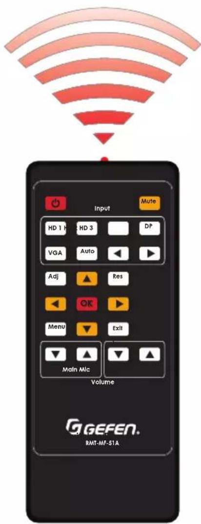
• (1) RMT-MF-51A Handheld IR Remote with (1) CR2025 battery
• (8) 3-pin Phoenix plugs
• (1) 6-pin Phoenix plug
• (2) Mounting Brackets
• (4) Unit-to-Mounting Bracket Screws (M3X5)
• (4) Self-adhesive rubber feet
• (1) Quick Start Guide
Important Safety Instructions .... ii
Warranty Information .... iii
Contacting Gefen Technical Support .... iv
Operating Notes ...... iv
Licensing...... v
Features and Package Contents...... vi
01 Getting Started
Panel Layout....2
Front....2
Back 3
Installation and Basic Operation 4
Connecting the Multi-Format 5x1 Scaler....4
Installation and Basic Operation 5
Sample Wiring Diagram 5
Network Configuration using Syner-G....6
IR Remote Control Unit....8
Remote Bottom - Installing the Batteries....9
02 Basic Operation
Introduction 12
Front Panel Controls....13
Powering the Multi-Format Scaler.... 13
Selecting a Video Input 13
Selecting an Audio Input 13
Using the IR Remote Control 14
OSD Menu 16
Accessing the Menu System....16
Main Menu 17
Menu System....18
Main ▶ Audio Input Menu.... 18
Main ▶ Audio Setup Menu .... 18
Main ▶ Video Setup Menu 19
Main ▶ Video Setup ▶ Output Resolution.... 20
Main ▶ Video Setup ▶ Picture Adjust.... 20
Main ▶ Video Setup ▶ Aspect Ratio ...... 21
Video Setup ▶ Overscan.... 21
Main ▶ Video Setup ▶ HDCP....22
Main ▶ VGA Menu 22
Main ▶ Network Menu....23
Main ▶ System Menu....23
Main ▶ System ▶ OSD Timeout.... 24
Main ▶ System ▶ Serial Baud Rate 25
Main ▶ System ▶ Factory Default....25
Main ▶ System ▶ Reboot....25
Main ▶ System ▶ System Update....25
Web Interface....26
Using the built-in Web Interface 26
Main ▶ Input Select.... 26
Main ▶ Volume....27
Main ▶ I/O Status....28
Setup ▶ Video 29
Setup ▶ VGA....30
Setup ▶ Serial 30
Setup ▶ Audio 31
Setup ▶ Names....31
Setup ▶ HPD Pulse....32
Setup ▶ HDCP Mode 32
EDID ▶ Mode 33
EDID ▶ Copy....33
EDID ▶ Info 34
EDID ▶ Upload/Download.... 34
Network ▶ Settings 35
System ▶ Settings.... 37
03 Advanced Operation
Firmware Update 40
RS-232 and IP Configuration....41
Using Telnet....41
Using RS-232....41
Commands List 42
04 Appendix
Default Settings....66
Specifications 67
Multi-Format 5x1 Scaler
01 Getting Started
Front
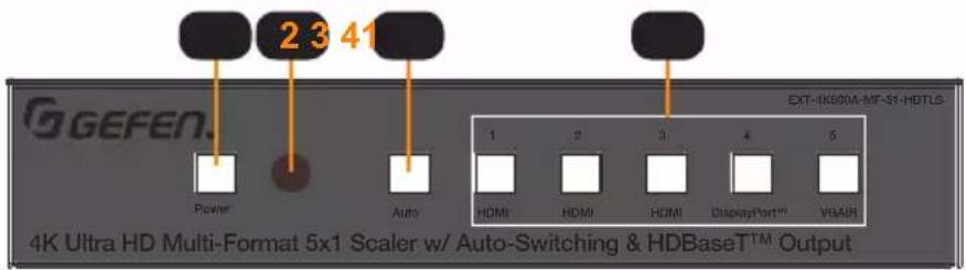
| ID Name Description | ||
| 1 | Power On | Power off: Not illuminated.Power on: Illuminates Blue. |
| 2 IR | IR receiver window for remote control. | |
| 3 AUTO | Enable/Disable Auto-Switching mode. When the button indicator illuminates blue, the device is in auto-switching mode.When the button indicator is off, the device is in manual-switching mode.Hold this button for >3 seconds to switch between modes. | |
| 4 | Input Sources(1 to 5) | Press these buttons for discrete source selection.The active source will be illuminated blue on the front panel. |
| 5 | IP Control | Connect an Ethernet cable between this jack and a Local Area Network for Web Interface and IP Control interface control. |
| 6 | RS-232 Port | Connect RS-232 Tx, Rx and Ground from an automation control device to this port using the included removable 3-pin “Captive Screw” Phoenix plug. Make sure to follow the pin assignment indicator on the unit panel.RS-232 extension and unit control are concurrently active. |
| 7 IR | In/Ext | Connect a Gefen EXT-RMT-EXTIRN IR Extender module (available separately) or the IR output of a third-party controller to this port. If using the IR Extender, place it within the line of sight of your handheld IR Remote. IR signals accepted by this port can be used to control the scaler and be extended via the optional HDBaseT Receiver to a remotely located device. |
| 8 IR | Out | Connect an EXT-IREMIT IR Emitter (sold separately) from this port to the IR sensor of the device to be controlled. IR signals are received from the remote HDBaseTTM receiver. |
| 9 | Input Control | This input control is for direct source input selection. Connect up to 5 momentary switches between the common pin (marked as C on panel) and the pin corresponding to each source. Pressing and releasing the button for each source will select that source.Pin Number Source1 HDMI 12 HDMI 23 HDMI 34 DisplayPortTM5 VGA/YPbPr/CVBS |
Back

ID Name Description
| 10 | Audio Out | Connect an amplifier to one of the included removable 3-pin “Captive Screw” Phoenix plugs and attach to the unbalanced stereo audio out port. Make sure to follow channel and polarity markings. The audio on this port will correspond to the selected video source and is mixed with Mic audio. |
| 11 | Audio In 1~5 | Connect unbalanced stereo audio sources to the included removable 3-pin “Captive Screw” Phoenix connectors plugs, observing channel and polarity markings, and attach them to one of the 5 audio input ports. Each audio input is assignable. |
| 12 | Bal In Port Mic/Line Switch | Connect either a balanced or unbalanced condenser/dynamic microphone, or other single-channel audio source to one of the included 3-pin “Captive Screw” Phoenix plugs and attach to this connector, observing polarity markings. The Mic/Line mode and 48V Phantom Power is set via this switch. |
| 13 | HDBase T^TM Out | Connect a CAT-5e or better cable, shielded CAT-6A preferred, up to the recommended length for a given resolution, from this port to the HDBase T^TM In port on the optional Receiver unit. |
| 14 | HDMI Out | Connect a Gefen Locking HDMI cable from this port to an HDMI capable display. The HDMI output includes internal HDMI audio or external audio from any of the audio inputs. |
| 15 | HDMI In (1-3) | Connect a Gefen Locking HDMI cable from an HDMI source to each of these ports. A DVI source can be connected using an adapter. |
| 16 | DisplayPort ^TM In (4) | Connect a DisplayPort 1.2 cable from a DisplayPort source to this port. |
| 17 | VGA In (5) | Connect a VGA cable from a VGA source (e.g. computer) to this port. Component (YPbPr) and Composite (CVBS) video can also be connected using an adapter cable. |
| 18 | Firmware Port | To update the system firmware, connect a USB thumb drive that contains the firmware file to this USB Type-A port. Firmware update requires the use of Gefen Syner-G ^TM software. |
| 19 | 12V DC | Connect the included 12V DC power supply to this power connector. |
Connecting the Multi-Format 5x1 Scaler
HDMI / DisplayPort™ / VGA / Audio
- Use Gefen HDMI cables to connect sources to the 3 HDMI In ports. Use a DisplayPort™ 1.2 cable to connect a source to the DisplayPort™ In. Use a VGA cable to connect a source to the VGA In port.
- Connect up to 5 un-balanced (single-ended) analog stereo audio sources to Inputs 1 through 5 using the 3-pin Phoenix plugs that came attached to the unit. Follow channel and polarity markings shown on the scaler's back panel. Any of these 5 audio inputs can be linked to any of the 5 video sources and embedded into the HDMI and HDBaseT™ outputs.
- Connect a balanced or unbalanced single channel audio source, a microphone with 48V Phantom Power or a non-powered microphone to the Bal-In 3-pin Phoenix connector. Follow ground and polarity markings shown on the scaler's back panel. Be sure to set the 3-position slide switch located to the right of the connector for the correct operation mode, 48V Mic, (Non-Powered) Mic or Line.
- Switch between the five inputs by pressing and releasing one of the input buttons on the front panel (marked 1 thru 5). The button for the selected input will illuminate. To activate Auto-Switching, press and hold the Auto button for 3 seconds or longer until it illuminates. To deactivate, press and hold the Auto button again for 3 seconds or longer. Press and release the Power button to turn the unit On or Off.
- Connect a Gefen HDMI cable between the HDMI Out port of the 5x1 Receiver and a display monitor.
- If extending AV to a remote display using HDBaseT™, use a CAT-5e cable (shielded CAT-6A preferred) up to the maximum recommended length for resolution/timing and color depth and connect between the HDBaseT™ Out port and the HDBaseT™ In port on the optional Receiver.
CAT-5 / RS-232 / Input Control
- The RS-232 port can be used to control the scaler and to extend 2-way RS-232 communications between the unit and the optional Receiver over the HDBaseT™ cable. The remote display can be controlled from the source side by an RS-232 control device, or the Scaler and a connected source can be controlled from the remote location. To connect an RS-232 device to the Scaler, remove the 3-pin Phoenix plug that came attached to the unit. Wire Tx, Ground and Rx from an RS-232-enabled device to the connector, and plug it back into the Scaler. To ensure proper operation, follow the pin-out of the connector as printed on the unit's enclosure.
- The Input Control contact-closure port can be used with up to 5 momentary switches. Each press and release of the button switches to the assigned input. Each switch can be connected between the C and the designated connection for each of the 5 inputs.
IR / Audio / IP / Power
- The IR In/Ext port facilitates IR control of the unit and extends IR from the source side to the viewing location. Connect a Gefen EXT-RMT-EXTIRN IR Extender module (available separately) or the IR output of a third-party controller to the IR In/Ext port. If using an HDBaseT Receiver, connect a Gefen EXT-IREMIT IR Emitter (sold separately) to the IR Out port of the Receiver and attach it to the IR sensor window of the device to be controlled.
- If using an HDBaseT™ Receiver, IR can also be extended from the remote end to the Scaler side to control the scaler as well as a source. Connect a Gefen EXT-IREMIT IR Emitter (sold separately) to the IR Out port and attach it to the IR sensor window of the device to be controlled. Connect a Gefen EXT-RMT-EXTIRN IR Extender or the IR output of a third-party controller to the IR In/Ext port of the Receiver.
Installation and Basic Operation
- To use de-embedded audio from the HDMI output with an outboard audio amplifier, wire the Audio Out of the 5x1 Scaler to your amplifier.
- To use the built-in Web Server, Telnet or UDP to control the scaler, connect an Ethernet cable from your Local Area Network (LAN) to the IP Control port. Use the Gefen Syner-G™ software to discover and configure IP settings. The default IP address is 192.168.1.72, and the password is 'admin' for the Administrator account.
- To provide power to the Scaler and the HDBaseT™ Receiver (through the link cable), connect the Scaler's power supply to its 12V DC jack and to an available electrical outlet. The Receiver can also be powered locally, but it cannot power the Scaler.
- The IR remote can be used at the Scaler side or remotely at the Receiver end. It provides access to Main Volume and Microphone Level controls and the intuitive On Screen Display (OSD).
Sample Wiring Diagram

flowchart
graph TD
    A["GEFEN"] --> B["RS-232 Device-To-Be-Controlled"]
    A --> C["RS-232 Third-Party Controller for 5x1 Switcher control and Extension"]
    A --> D["RS-232 Device-To-Be-Controlled"]
    A --> E["RS-232 Third-Party Controller for 5x1 Switcher control and Extension"]
    A --> F["RS-232 Third-Party Controller for 5x1 Switcher control and Extension"]
    A --> G["RS-232 Third-Party Controller for 5x1 Switcher control and Extension"]
    A --> H["RS-232 Third-Party Controller for 5x1 Switcher control and Extension"]
    A --> I["RS-232 Third-Party Controller for 5x1 Switcher control and Extension"]
    A --> J["RS-232 Third-Party Controller for 5x1 Switcher control and Extension"]
    A --> K["RS-232 Third-Party Controller for 5x1 Switcher control and Extension"]
    A --> L["RS-232 Third-Party Controller for 5x1 Switcher control and Extension"]
    A --> M["RS-232 Third-Party Controller for 5x1 Switcher control and Extension"]
    A --> N["RS-232 Third-Party Controller for 5x1 Switcher control and Extension"]
    A --> O["RS-232 Third-Party Controller for 5x1 Switcher control and Extension"]
    A --> P["RS-232 Third-Party Controller for 5x1 Switcher control and Extension"]
    A --> Q["RS-232 Third-Party Controller for 5x1 Switcher control and Extension"]
    A --> R["RS-232 Third-Party Controller for 5x1 Switcher control and Extension"]
    A --> S["RS-232 Third-Party Controller for 5x1 Switcher control and Extension"]
    A --> T["RS-232 Third-Party Controller for 5x1 Switcher control and Extension"]
    A --> U["RS-232 Third-Party Controller for 5x1 Switcher control and Extension"]
    A --> V["RS-232 Third-Party Controller for 5x1 Switcher control and Extension"]
    A --> W["RS-232 Third-Party Controller for 5x1 Switcher control and Extension"]
    A --> X["RS-232 Third-Party Controller for 5x1 Switcher control and Extension"]
    A --> Y["RS-232 Third-Party Controller for 5x1 Switcher control and Extension"]
    A --> Z["RS-232 Third-Party Controller for 5x1 Switcher control and Extension"]
    A --> AA["RS-232 Third-Party Controller for 5x1 Switcher control and Extension"]
    A --> AB["RS-232 Third-Party Controller for 5x1 Switcher control and Extension"]
    A --> AC["RS-232 Third-Party Controller for 5x1 Switcher control and Extension"]
    A --> AD["RS-232 Third-Party Controller for 5x1 Switcher control and Extension"]
    A --> AE["RS-232 Third-Party Controller for 5x1 Switcher control and Extension"]
    A --> AF["RS-232 Third-Party Controller for 5x1 Switcher control and Extension"]
    A --> AG["RS-232 Third-Party Controller for 5x1 Switcher control and Extension"]
    A --> AH["RS-232 Third-Party Controller for 5x1 Switcher control and Extension"]
    A --> AI["RS-232 Third-Party Controller for 5x1 Switcher control and Extension"]
    A --> AJ["RS-232 Third-Party Controller for 5x1 Switcher control and Extension"]
    A --> AK["RS-232 Third-Party Controller for 5x1 Switcher control and Extension"]
    A --> AL["RS-232 Third-Party Controller for 5x1 Switcher control and Extension"]
    A --> AM["RS-232 Third-Party Controller for 5x1 Switcher control and Extension"]
    A --> AN["RS-232 Third-Party Controller for 5x1 Switcher control and Extension"]
    A --> AO["RS-232 Third-Party Controller for 5x1 Switcher control and Extension"]
    A --> AP["RS-232 Third-Party Controller for 5x1 Switcher control and Extension"]
    A --> AQ["RS-232 Third-Party Controller for 5x1 Switcher control and Extension"]
    A --> AR["RS-232 Third-Party Controller for 5x1 Switcher control and Extension"]
    A --> AS["RS-232 Third-Party Controller for 5x1 Switcher control and Extension"]
    A --> AT["RS-232 Third-Party Controller for 5x1 Switcher control and Extension"]
    A --> AU["RS-232 Third-Party Controller for 5x1 Switcher control and Extension"]
    A --> AV["RS-232 Third-Party Controller for 5x1 Switcher control and Extension"]
    A --> AW["RS-232 Third-Party Controller for 5x1 Switcher control and Extension"]
    A --> AX["RS-232 Third-Party Controller for 5x1 Switcher control and Extension"]
    A --> AY["RS-232 Third-Party Controller for 5x1 Switcher control and Extension"]
    A --> AZ["RS-232 Third-Party Controller for 5x1 Switcher control and Extension"]
    A --> BA["RS-232 Third-Party Controller for 5x1 Switcher control and Extension"]
    A --> BB["RS-232 Third-Party Controller for 5x1 Switcher control and Extension"]
    A --> BC["RS-232 Third-Party Controller for 5x1 Switcher control and Extension"]
    A --> BD["RS-232 Third-Party Controller for 5x1 Switcher control and Extension"]
    A --> BE["RS-232 Third-Party Controller for 5x1 Switcher control and Extension"]
    A --> BF["RS-232 Third-Party Controller for 5x1 Switcher control and Extension"]
    A --> BG["RS-232 Third-Party Controller for 5x1 Switcher control and Extension"]
    A --> BH["RS-232 Third-Party Controller for 5x1 Switcher control and Extension"]
    A --> BI["RS-232 Third-Party Controller for 5x1 Switcher control and Extension"]
    A --> BJ["RS-232 Third-Party Controller for 5x1 Switcher control and Extension"]
    A --> BK["RS-232 Third-Party Controller for 5x1 Switcher control and Extension"]
    A --> BL["RS-232 Third-Party Controller for 5x1 Switcher control and Extension"]
    A --> BM["RS-232 Third-Party Controller for 5x1 Switcher control and Extension"]
    A --> BN["RS-232 Third-Party Controller for 5x1 Switcher control and Extension"]
    A --> BO["RS-232 Third-Party Controller for 5x1 Switcher control and Extension"]
    A --> BP["RS-232 Third-Party Controller for 5x1 Switcher control and Extension"]
    A --> BQ["RS-232 Third-Party Controller for 5x1 Switcher control and Extension"]
    A --> BR["RS-232 Third-Party Controller for 5x1 Switcher control and Extension"]
    A --> BS["RS-232 Third-Party Controller for 5x1 Switcher control and Extension"]
    A --> BT["RS-232 Third-Party Controller for 5x1 Switcher control and Extension"]
    A --> BU["RS-232 Third-Party Controller for 5x1 Switcher control and Extension"]
    A --> BV["RS-232 Third-Party Controller for 5x1 Switcher control and Extension"]
    A --> BW["RS-232 Third-Party Controller for 5x1 Switcher control and Extension"]
    A --> BX["RS-232 Third-Party Controller for 5x1 Switcher control and Extension"]
    A --> BY["RS-232 Third-Party Controller for 5x1 Switcher control and Extension"]
    A --> BZ["RS-232 Third-Party Controller for 5x1 Switcher control and Extension"]
    A --> CA["RS-232 Third-Party Controller for 5x1 Switcher control and Extension"]
    A --> CB["RS-232 Third-Party Controller for 5x1 Switcher control and Extension"]
    A --> CC["RS-232 Third-Party Controller for 5x1 Switcher control and Extension"]
    A --> CD["RS-232 Third-Party Controller for 5x1 Switcher control and Extension"]
    A --> CE["RS-232 Third-Party Controller for 5x1 Switcher control and Extension"]
    A --> CF["RS-232 Third-Party Controller for 5x1 Switcher control and Extension"]
    A --> CG["RS-232 Third-Party Controller for 5x1 Switcher control and Extension"]
    A --> CH["RS-232 Third-Party Controller for 5x1 Switcher control and Extension"]
    A --> CI["RS-232 Third-Party Controller for 5x1 Switcher control and Extension"]
    A --> CJ["RS-232 Third-Party Controller for 5x1 Switcher control and Extension"]
    A --> CK["RS-232 Third-Party Controller for 5x1 Switcher control and Extension"]
    A --> CL["RS-232 Third-Party Controller for 5x1 Switcher control and Extension"]
    A --> CM["RS-232 Third-Party Controller for 5x1 Switcher control and Extension"]
    A --> CN["RS-232 Third-Party Controller for 5x1 Switcher control and Extension"]
    A --> CO["RS-232 Third-Party Controller for 5x1 Switcher control and Extension"]
    A --> CP["RS-232 Third-Party Controller for 5x1 Switcher control and Extension"]
    A --> CQ["RS-4K600A-MF-SI-HBTLS\nEXT-UHDA-HBTL-RX"]
Network Configuration using Syner-G
- Download the application here: http://www.gefen.com/synerg/Launch the Gefen Syner-G application.
- Select the EXT-4K600A-MF-51-HBTLS from the list of products.
| Select Function | |||
| Discover and Configure IP Manage a Product EDID Editor | |||
| My PC | 192.168.0.150 | 8C:AE:4C:FF:11:BA | Ethernet 5 |
| Product Name | IP Address | MAC Address | Description |
| EXT-UHDV-KA-LANS-RX | 192.168.0.186 | 00:1C:91:05:43:E0 | EXT-UHDV-KA-LANS-RX |
| EXT-UHDV-KA-LANS-TX | 192.168.0.50 | 00:1C:91:05:40:20 | EXT-UHDV-KA-LANS-TX |
| EXT-UHDV-KA-LANS-TX | 192.168.0.11 | 00:1C:91:03:C0:01 | Samsung |
| EXT-4K600A-MF-51-HBT | 192.168.0.72 | 00:1C:91:03:80:09 | EXT-4K600A-MF-51-HBT |
| EXT-UHDV-KA-LANS-RX | 192.168.0.30 | 00:1C:91:05:40:01 | EXT-UHDV-KA-LANS-RX |
| EXT-CU-LAN | 192.168.0.74 | 00:1C:91:04:62:83 | EXT-CU-LAN |
-
Under the Device Settings section, select either Static or DHCP from the IP Mode drop-down list.
-
Select Static to manually enter the IP address, subnet mask, and gateway IP. Consult with your network administrator, if necessary.
- Select DHCP to let the DHCP server automatically assign the IP address, subnet mask, and gateway IP.
- Telnet Port is fixed at 80.
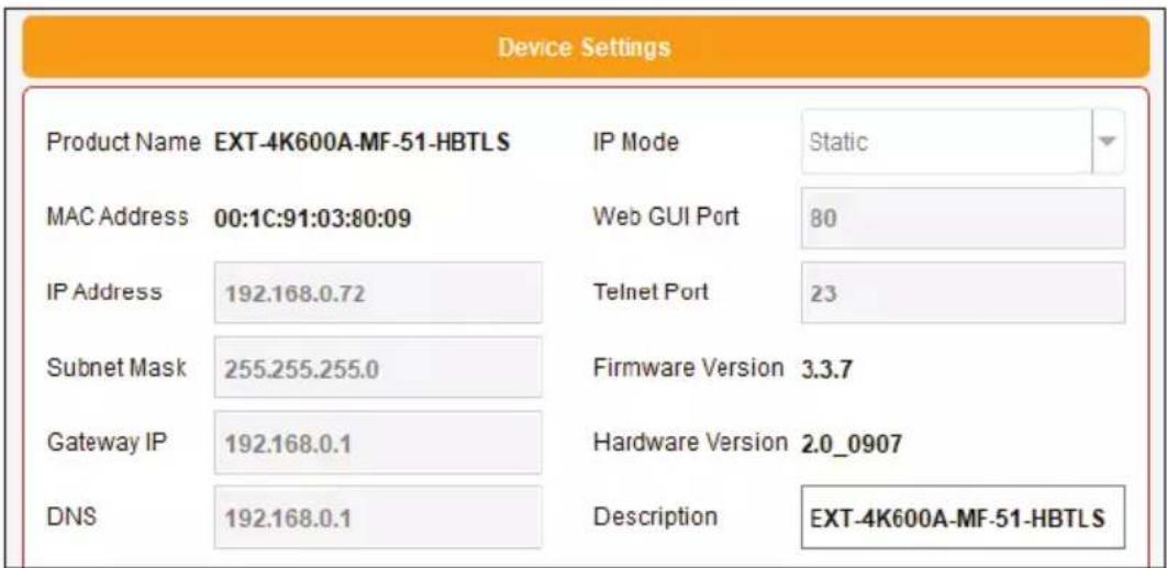

NOTE: The default IP address is 192.168.1.72
- Click the Save button at the bottom of the screen.

- After saving, select Reboot for the new network settings to take effect.
- Use the IP address of the switcher to access the built-in web interface or start a Telnet session. See the following for more information:
• Web Interface, pg. 26
• RS-232 and IP Configuration, pg. 41
IR Remote Control Unit
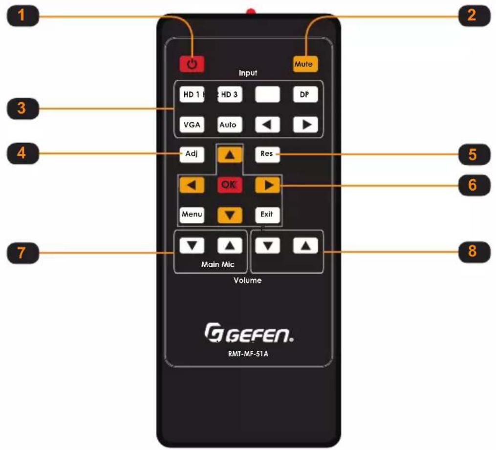
ID Name Description
| 1 Power | Press this button to toggle between On and Off power modes. Powering on the unit via IR from the HDBaseT ^TM receiver is not possible as the link is not active when the unit is in standby mode. This button is fully functional when communicating directly with the main unit.It is possible to power off the 5x1 switcher/scaler from the remote location via the IR remote. The scaler, however, cannot be turned back on from the remote location. |
| 2 Mute Toggles mute/un-mute of both analog and HDMI outputs. | |
| 3 Inputs | Press these buttons for discrete source selection. The ◀ and ►buttons can be used to cycle between inputs in numerical order. |
| 4 ADJ Performs an auto-sync action for the VGA input. | |
| 5 RES | Resolution will cycle on each press of this button based on available output resolutions. Long pressing this button will reset the resolution to 720p 60Hz. |
| 6 Menu buttons | MENU: Activates/Deactivates OSD menu.EXIT: Exit OSD menu or cancel current operation.OK: Option confirmationUP/DOWN/LEFT/RIGHT: OSD menu navigation |
| 7 Main Volume | Decrease (▼) or increase (▲) audio output volume (HDMI, HDBaseT ^TM , and Audio out ports). |
| 8 Mic Volume | Decrease (▼) or increase (▲) MIC input audio volume. |
Remote Bottom - Installing the Batteries

| ID Name | Description | |
| 1 Battery slot | Holds battery carriage in place. | |
| 2 Release Tab | Press inward with your thumb to release the tab that holds the battery carriage in place. Remove and replace the battery, then slide and snap the battery carriage back in to place. | |
| 3 Battery Carriage | Holds the lithium battery for operating the IR remote. Use only a CR2025 3V Lithium Battery. | |
Multi-Format 5x1 Scaler
02 Basic Operation
EXT-4K600A-MF-51-HBTLS
4K Ultra HD 600 MHz Multi-Format 5x1 Scaler w/ Auto-Switching & Split HDMI & HDBaseT™ Outputs
Auto-Switch 4K Ultra HD 600 MHz HDMI, DisplayPort™ 1.2 and VGA. Scale and extend up to 70 meters/230 feet, over a single CAT-5.
The EXT-4K600A-MF-51-HBTLS is a 5x1 Presentation Switcher with three 4K 600 MHz HDMI, one DisplayPort™ 1.2, one VGA, five independently assignable stereo analog audio and one balanced/unbalanced microphone/line input.
The latter features switchable 48V Phantom Power and Ducking. The five video inputs, along with their embedded or assigned audio, can be switched automatically or manually. Control options include the front panel, hand-held IR remote with On-Screen-Display, electrical IR, RS-232, IP Control interface, web server interface and contact closure.
The split HDMI and HDBaseT ^™ outputs feature a scaler, configurable to 3840 x 2160, 30 Hz, 4:4:4. They feed a local and a remote display simultaneously, adding flexibility in larger presentation environments. The Switcher and its recommended Receiver [the EXT-UHDA-HBTL-RX, (sold separately)] use Gefen's implementation of the HDBaseT ^™ technology to extend the HDMI output of the Switcher up to 230 feet/70 meters at 1080p Full HD and up to 130 feet/40 meters at 4K, using one CAT-5e or better cable.
The HDMI and DisplayPort™ inputs support resolutions up to 4K DCI (4096 x 2160) 60 Hz 4:4:4, with HDCP 2.2 and 1.4. The HDMI input and output, and the HDBaseT™ output support 2 channels of LPCM digital audio. The VGA input supports resolutions up to WUXGA (1920 x 1200) and 1080p Full HD.
When used with third-party adaptors, the VGA input also supports Component (YPbPr) and Composite video. The Switcher features an analog L/R audio de-embedder. The optional Receiver also features analog and digital audio (optical and coaxial) outputs. Any or all audio outputs can be connected to sound-reinforcement systems at the source side or the remote end, adding impact and presence to AV presentations.
The 5x1 Switcher features Advanced EDID Management to ensure that sources are optimized for the displays in use. The Switcher, when used with the optional HDBaseT™ Receiver, provides 2-way RS-232 and IR extension. This facilitates the control of the Switcher, AV sources placed near the Switcher and the remote display or another device placed near the Receiver unit.
Industry-standard Power-Over-HDBaseT™ (POH) technology provides power from the Switcher to the Receiver over the same cable that extends the AV signal. The Switcher features an integrated IR Sensor on its front panel, as well as an electrical IR input.
If the switcher is mounted in a location where its IR sensor is not within line of sight, a Gefen EXT-RMT-EXTIRN IR Extender Module or a third-party controller with electrical IR output can be connected to the IR input on its back panel.
The 5x1 Switcher features a compact form-factor that can be placed on a shelf or securely mounted on or under a surface. The optional Receiver's small, ultra-low-profile enclosure can be securely surface-mounted and conveniently hidden away from sight in the equipment closet or behind the display. Locking HDMI ports on the Switcher and locking power jacks on both units ensure long-lasting and reliable connections.
NOTE: Shielded (STP) CAT-5e (or better) cable is recommended. An unshielded (UTP) CAT-5e (or better) cable may be acceptable depending on cable quality, but isn't the preferred choice. Care should always be given to keep these cables away from power lines and other sources of electromagnetic interference.
Powering the Multi-Format Scaler
- Make sure the included 12V DC power supply is connected from the Multi-Format Scaler to an available electrical outlet.
- Press and release the Power button on the front panel.
- The power button will illuminate blue.


NOTE: The Multi-Format Scaler can also be turned on and off with the IR Remote Control, the Web Interface, or by an external controller using either RS-232 or IP Telnet control.
Selecting a Video Input
The Multi-Format Scaler allows you to switch between five simultaneous connections. By default, AUTO is active, as well as the auto-detected Input.
Press the button corresponding to your desired Input. The selected button will illuminate blue.
Select from the following inputs: AUTO, HDMI (1-2-3), DisplayPort and VGA.


NOTE: The Video Input Selection can also be changed with the IR Remote Control, the Web Interface, or by an external controller using either RS-232 or IP Telnet control, or via the Contact Closure Inputs on the back panel.
Selecting an Audio Input
Audio inputs must be selected and/or paired with video inputs using the built-in Web interface or On Screen Display (OSD). See Setup ▶ Audio (page 31) for more information.
Using the IR Remote Control
You can use the included IR Remote Control to operate the Multi-Format Scaler by pointing the remote at the IR Window on the unit.
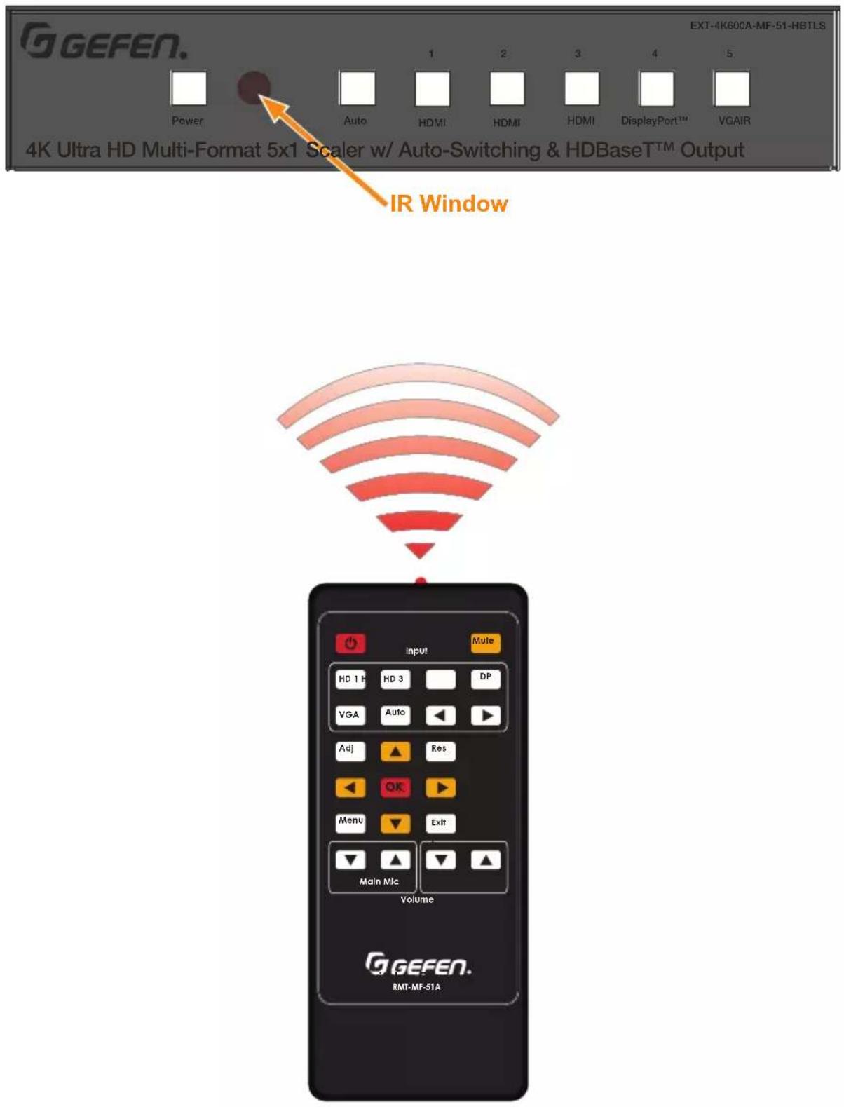
Using the IR Remote Control
If the Multi-Format Scaler is concealed in a cabinet or otherwise out of range of the remote, you can plug in a Gefen IR Extender (Gefen part no. EXT-RMT-EXTIR, available separately) to the IR Ext port on the back panel and place the sensor where it will be in range of the remote.
IR Extender

Accessing the Menu System
Input selection can be controlled using the front panel of the The Multi-Format Scaler. However, the included IR remote control must be used to access the built-in menu system. The menu system is used to manage and control audio, video, and system features.

To access the menu system, press the Menu button on the included IR remote control. The default time-out value for the menu system is 5 seconds. This value can be changed using options found in the System ▶ OSD Timeout menu (page 24).

The switcher provides a powerful OSD operation menu. Press the MENU button on IR remote to view the menu and change settings.

Main Menu
The Main Menu includes Audio Input, Audio Setup, Video Setup, VGA, Network and System options.
| Main Menu |
| Audio Input |
| Audio Setup |
| Video Setup |
| VGA |
| Network |
| System |
The Main Menu includes Audio Input, Audio Setup, Video Setup, VGA, Network and System options.
- Use the IR Remote Control to navigate menu options.
- Press the IR Remote Menu button at any time to save settings and return to the previous menu.
- On sub-menus, an Asterisk (*) adjacent to an option indicates the currently selected option.
- Orange indicates the menu title, and selected options appear in red.
Main ▶ Audio Input Menu
| 1. Press the Menu button on the IR remote control. The menu system will be displayed.2. Select Audio Input to choose an audio source. | Main MenuAudio InputAudio SetupVideo SetupVGANetworkSystem |
| 3. Press ▲ or ▼ to highlight an option, and press the OK button. | Audio InputEmbedded AudioExternal 1*External 2External 3External 4External 5No AudioPress MENU to go Back |
Main ▶ Audio Setup Menu
| 1. SelectAudio Setupto access audio setup options. |
Main ▶ Audio Setup
- Press ▲ or ▼ to highlight an option, and press the OK button repeatedly to cycle through available options: Emb, Ext (1 through 5), No Audio and No Change.
Mixer Mode options include: On, Off and Auto.
| Audio Setup | |
| HDMI 1 | Ext 1 |
| HDMI 2 | Emb |
| HDMI 3 | Emb |
| Display Port 4 | Emb |
| VGA | Ext 1 |
| Mixer Mode | On |
| Press MENU to go Back | |
Main ▶ Video Setup Menu
-
Select Video Setup to access video setup options.
-
Select Output Resolution to access video output resolution options.
| Main Menu |
| Audio Input |
| Audio Setup |
| Video Setup |
| VGA |
| Network |
| System |
| Video Setup |
| Output Resolution |
| Picture Adjust |
| Aspect Ratio |
| Overscan |
| HDCP |
| Press MENU to go Back |
Main ▶ Video Setup ▶ Output Resolution
- Press ▲ or ▼ to highlight an option, then press the OK button.
NATIVE *
Main ▶ Video Setup ▶ Picture Adjust
Picture Adjust
- Select Picture Adjust to access adjustment options.
Contrast 50
- Press the ▲ or ▼ buttons to highlight an option, then press ◀ or ▶ to adjust the value.
Main ▶ Video Setup ▶ Aspect Ratio
| 1. Select Aspect Ratio to access aspect ratio options. |  |
| 2. Press the ▲ or ▼ buttons to highlight 16:9, 4:3 or AUTO, then press OK. |  |
Video Setup ▶ Overscan
| 1. Select Overscan to access overscan Vertical and Horizontal overscan options. | 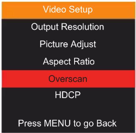 |
| 2. Press the ▲ or ▼ buttons to highlight an option, then press ◀ or ▶ to adjust the value. |  |
Main ▶ Video Setup ▶ HDCP
| 1. Select HDCP to access options. |  |
| 2. Press the ▲ or ▼ buttons to highlight an option, then press OK to select. |  |
Main ▶ VGA Menu
| 1. Select VGA to access VGA output options. | 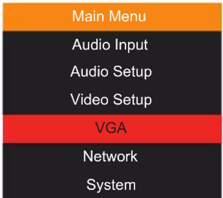 |
| 2. For Auto Sync, highlight the option and press OK.Press the ▲ or ▼ buttons to highlight an adjustable option, then press ◀ or ▶ to change the value. |  |
Main ▶ Network Menu
| 1. SelectNetworkto access network setting options. | Main MenuAudio InputAudio SetupVideo SetupVGANetworkSystem |
| 2. Press the ▲ or ▼ buttons to highlight a setting.ForIP MODE, press OKto toggle options.For Network settings, highlight the setting then press ◀ or ▶ to change numbers. Press OKto accept and move to the next number.SelectSAVEwhen finished. | NetworkIPMODESTATICIPaddress:192.168.001.072Subnet :255.255.255.000Gateway :192.168.001.001TelnetPort00023SavePress MENU to go Back |
Main ▶ System Menu
| 1. Select System to access system options. | Main MenuAudio InputAudio SetupVideo SetupVGANetworkSystem |
| 2. Press the ▲ or ▼ buttons to highlight an option, then press OK to select. | SystemOSD TimeoutSleep TimeTest PatternSerial Baud RateFactory DefaultRebootSoftware UpdatePress MENU to go Back |
Main ▶ System ▶ OSD Timeout
- Press the ▲ or ▼ buttons to highlight a setting. Press OK select an option.
| OSD Timeout |
| OFF |
| 5 seconds |
| 10 seconds * |
| 30 seconds |
| 60 seconds |
| Press MENU to go Back |
Main ▶ System ▶ Sleep Timer
- Press the ▲ or ▼ buttons to highlight an option. Press OK select an option.
| Sleep Timer |
| OFF * |
| 10 Min |
| 30 Min |
| 1 Hour |
| 3 Hour |
| Press MENU to go Back |
Main ▶ System ▶ Test Pattern
- Press the ▲ or ▼ buttons to highlight a setting. Press OK select an option.
| Test Pattern |
| OFF * |
| White |
| Red |
| Green |
| Blue |
| Black |
| Press MENU to go Back |
Main ▶ System ▶ Serial Baud Rate
| 1. Press the ▲ or ▼ buttons to highlight a setting. Press OK select an option. | 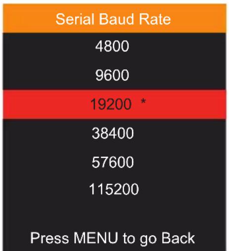 |
Main ▶ System ▶ Factory Default
| 1. Once selected, press the ◀ to choose Yes, or press ► to choose No. |  |
Main ▶ System ▶ Reboot
| 1. Once selected, press the ◀ to choose Yes, or press ▶ to choose No. |  |
Main ▶ System ▶ System Update
| 1. Once selected, press the ◀ to choose Yes, or press ► to choose No. |  |
Using the built-in Web Interface
This is the login page. Options for login are Administrator and Operator. Password defaults are 'admin' and 'operator'. The Web Interface is divided into six tabs at the top of the screen: Main, Setup, Names, EDID, Network, System. Some tabs have sub-tabs.

Default IP Address
192.168.1.72
Username
Select the username from the drop-down list:
- Operator
- Administrator
Administrator login provides unrestricted access to all features and settings. Operator login limits access to routing features, preset selection, and input/output info.
Password
Enter the password for the associated username.
Main ▶ Input Select
This is the Main tab containing day-to-day operational items.

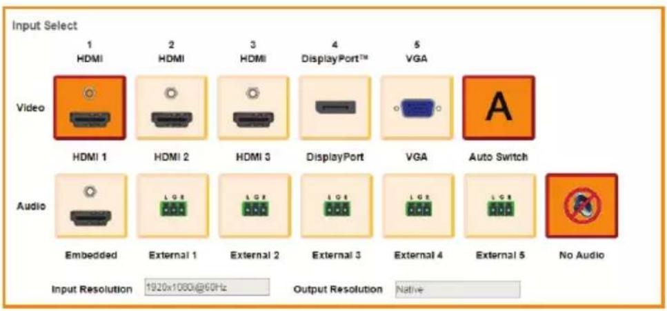
Illuminated orange are the current Video and Audio Inputs in use. Click on desired Video or Audio input to make changes.
With Auto Switch enabled, the scaler will automatically switch the input when it detects a new input source. The Auto Switch function uses an Auto Switch Fallback feature to scan for the active input source starting from HDMI 1.
For example: All 3 HDMI ports are connected and the input is set to HDMI 2. If you unplug or turn off HDMI 2, it will first switch to HDMI 1 since an HDMI 1 signal is present. If not, it will switch to HDMI 3 if a signal is present.
This occurs only if the current source is turned off.
The No Audio button is a pseudo audio input that offers no audio, but it's separate from mute.
The current Input Resolution and Output Resolution are displayed below the input options.
Main ▶ Volume
Adjust the Main volume and Microphone volume.

Click Mute, On or Off for Main and Microphone volume.
To adjust the volume level, use the sliders to adjust the setting up or down.
Main ▶ I/O Status
This tab indicates the status of the inputs and outputs. The unit's power status is displayed at the top right of the status window, as well as the Help button.

Input
The Input table displays the Feature and Input status for:
Color Depth: The color depth of the input signal (8-bit, 10-bit, etc).
Color Space : The color space (RGB or YCbCr) of the input signal.
HDCP : Displays whether or not HDCP is detected on the input.
Active Signal: Detects whether an input signal is present or not.
Horizontal Resolution: The horizontal resolution (in pixels) of the input signal.
Vertical Resolution: The vertical resolution (in pixels) of the input signal.
Progressive / Interlaced : Detects whether the input signal is progressive or interlaced.
Refresh Rate: The refresh rate (frequency) of the input signal.
Video Mode : The video mode (HDMI or DVI) of the input signal.
Auto Input Format : The current audio input format..
Output
The Output table displays the Feature and Output status for:
RSENSE : Displays the current Rsense state (On/Off).
HPD : Displays the current HPD state.
HDCP : Displays the current HDCP state. The HDCP state can be set using the #set_output_HDCP command or through the Setup ▶ HDCP section of the Web interface or OSD menu.
Video Mode : Displays the current output video mode.
Setup ▶ Video
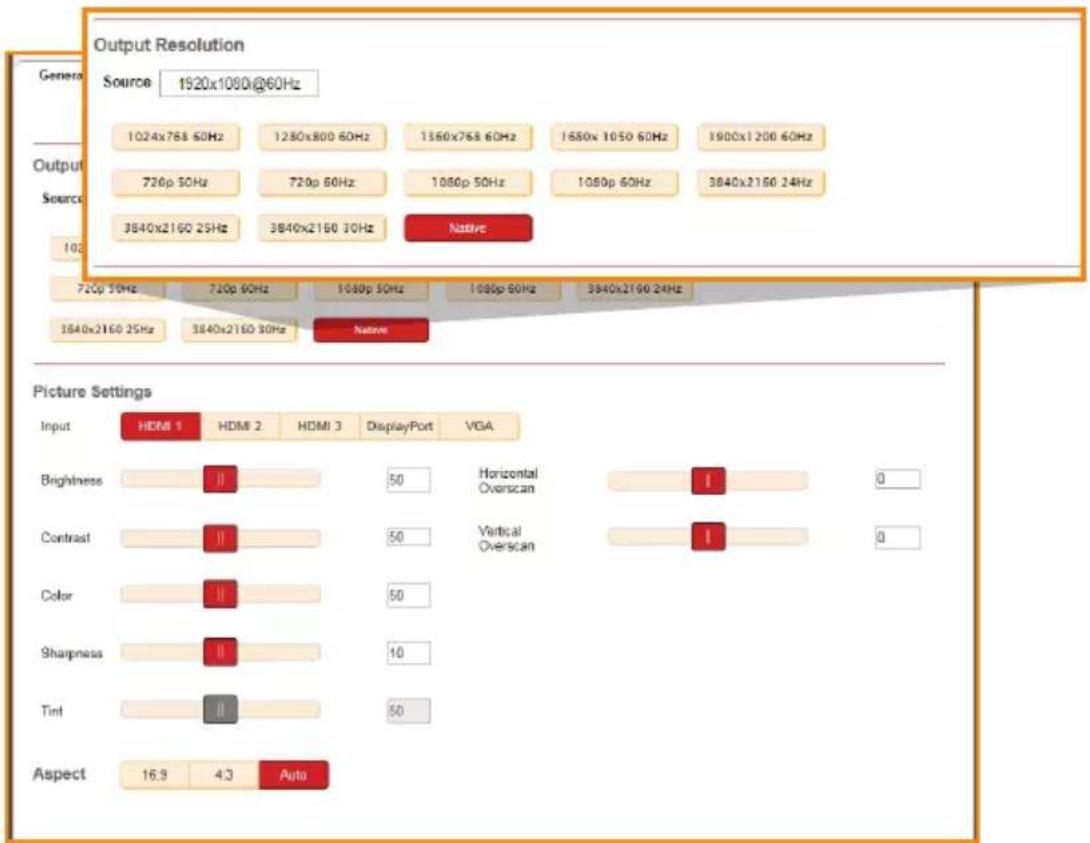
This tab is the main configuration page for the input and outputs. The Output Resolution modes include 12 presets and Native.
Native
The Native mode will attempt to set the output of the unit based on the native resolution detected in the EDID of the connected display.
Picture Settings
If desired, select an Input, then use the option sliders to set the Brightness, Contrast, Color, Sharpness and Tint. You can also set them manually by typing in numeric values (0 - 100).
Aspect Ratio
Choose an Aspect Ratio for the selected Input: 16:9, 4:3 or Auto.
Horizontal / Vertical Overscan
Use the sliders to adjust the Horizontal or Vertical overscan for the selected Input.
Setup ▶ VGA
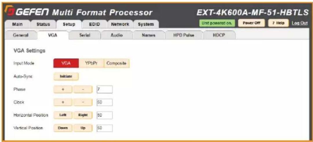
This tab allows you to configure the window VGA Settings for the three VGA input modes: VGA, YPbPr and Composite.
Input Mode
Select the input mode to adjust: VGA, YPbPr or Composite.
Note: Auto switching will not be active for composite or component (YPbPr) video when these modes are enabled.
Auto-Sync
Click the Initiate button to activate Auto-Sync for the selected input mode.
Phase / Clock
Click + or – to adjust values for Phase and Clock settings.
Horizontal Position
Click the Left or Right buttons to adjust the Horizontal Position.
Vertical Position
Click the Down or Up buttons to adjust the Vertical Position.
Setup ▶ Serial
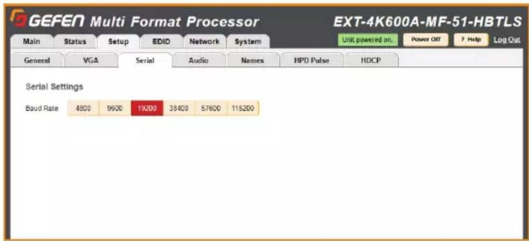
Select the Baud Rate for the Serial connection: 4800, 9600, 19200, 38400, 57600 or 115200. The default setting is 19200.
Setup ▶ Audio
This tab allows you to configure an Audio Link setting for each input (HDMI 1-3, DisplayPort and VGA) and global Audio Mixer settings.
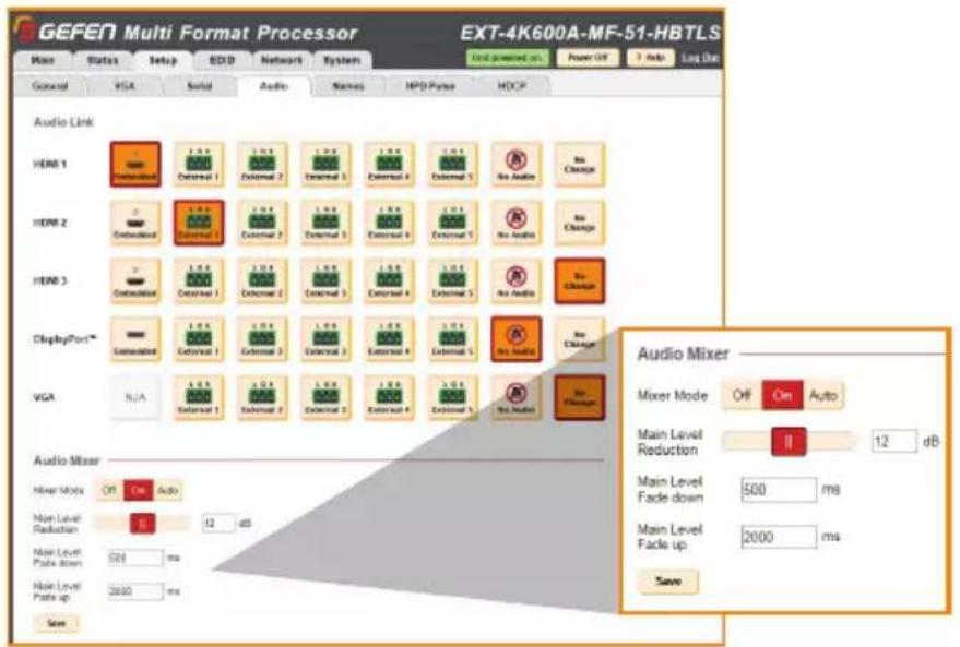
Audio Link
For each Input, click the option that represents the audio source you'd like to use when that input is selected. Select No Audio to have no audio, or select No Change keep the current audio source that is being used active when that input is selected.
Audio Mixer
Mixer Mode: Enable or disable the microphone input. The On setting will enable microphone mixing, and the Off setting will disable microphone mixing. The Auto setting will enable a ducking circuit that will reduce the current audio source level to allow the microphone audio to be heard more clearly.
Main Level Reduction: Move the slider to adjust the db setting. This is the amount of volume that the Main level will reduce when Mic audio is detected in the Auto Mode.
Main Level Fade down: Type in the desired fade down value. This is the amount of time that the main volume will take to reach the set reduction level value after audio is detected in Auto Mode.
Main Level Fade up: Type in the desired fade down value. This is the amount of time that it will take for volume to return to its precious level once Mic audio is no longer detected in Auto Mode.
Click Save to enable the new settings.
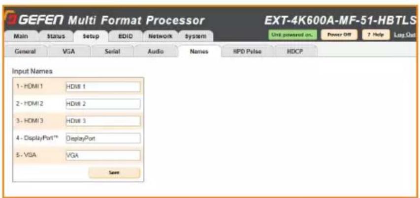
Setup ▶ Names
This tab allows you to Label/Name each of the user Input source labels that appear in the web interface and on-screen.
Setup ▶ HPD Pulse
This tab is used to perform HPD (Hot Plug Detect) pulse events.

HPD is a low voltage pin in the HDMI cable that is set either HIGH or LOW that indicated the presence of a cable connection.
Momentarily changing this voltage from HIGH to LOW and then back to HIGH creates a Pulse that disconnects and reconnects, triggering a connection reset between the unit and the input source(s) without unplugging and plugging in the HDMI cable(s).
Setup ▶ HDCP Mode
This tab will configure the HDCP (High-bandwidth Digital Content Protection) options available.
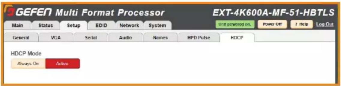
Always On / Active
Click the Always On button to encrypt all output content with HDCP. Active will set the output HDCP encryption based on the selected source's current HDCP status.
EDID ▶ Mode
This tab is used to configure the EDID (Extended Display Identification Data), typically a 256 byte file that is hosted on a sink (display or other endpoint device) that contains video and audio capability information for that device.

There are three EDID modes:
Internal
Pre-configured and non-customizable EDIDs that have specific limitations on the resolution and number of allowable audio channels.
External
An EDID that is “pass-through” from a connected display through the unit and directly to the source with little to no modification.
Custom
The User Defined EDID can be uploaded, and each input has a memory location that stores the selected EDID. When using the Custom EDID mode, the EDID Lock function will be available to prevent accidental overwrite of the EDID that has been uploaded.
EDID ▶ Copy
The EDID Copy option provides the ability to copy the HDMI or HDBaseT Output or any EDID that is currently stored in an input's memory to another input.

When a custom EDID has been uploaded to an input, use this option to copy it to the other inputs. Select an EDID to copy, then select the copy destination.
NOTE: The EDID Mode of the destination must be set to Custom, and the EDID Lock must be turned off to allow the copy procedure. The Copy button will then be available.
EDID ▶ Info
This tab is an information page that displays the current settings for the selected EDID.
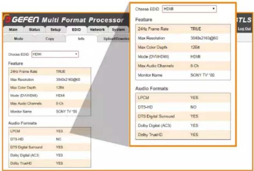
Select the output or any of the 4 digital inputs to view the EDID information. Information is sourced from the input's local memory, so the information displayed depends on which mode is currently in use.
EDID ▶ Upload/Download
This tab is used to download an EDID to the computer or to upload an externally sourced EDID .bin file for use with an input.
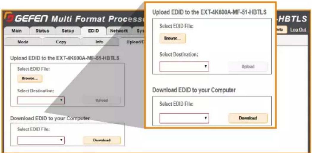
To upload an externally sourced EDID, select the Browse button and then select an EDID .bin file from the computer. Once selected, the filename will be displayed. You can then select an input as the destination and click Upload.
NOTE: The desired input EDID mode must be set to Custom to enable the option in the destination drop-down menu.
You can also download an EDID to your computer by selecting an option from the Select EDID File drop-down menu. Options include the Output, any of the 4 inputs or the 2 internal EDIDs. A downloaded EDID may be loaded into the Gefen Syner-G™ or other EDID modification software to then customize and re-upload back to the unit.
Network ▶ Settings
This tab is used to configure all of the network related options on the switcher. Once revisions have been made, select Save. Select the Set Network Defaults option to return to default network settings.
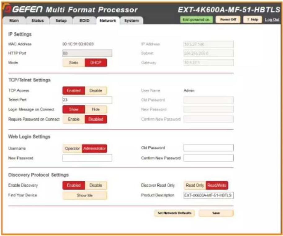
IP Settings
MAC Address
The MAC address of the switcher. The MAC address cannot be changed.
Mode
The network mode setting.
| Options |
| Static |
| DHCP |
IP Address
Enter the new IP address of the switcher in this field. This option is only available if the network mode is set to Static.
Subnet
Enter the new subnet mask of the switcher in this field. This option is only available if the network mode is set to Static.
Gateway
Enter the new gateway (router) address in this field. This option is only available if the network mode is set to Static.
HTTP Port
Shows the port used by HTTP (web interface).
Network ▶ Settings (continued)

TCP/Telnet Settings
Enable TCP Access
Click Enable to make TCP available, or click Disable to disable TCP access.
TCP Port
Type in the a TCP port number. Default is set to 23.
Login Message on Connect
Click Show to display the Telnet Welcome Message. Click Hide to disable the Telnet Welcome Message.
Require Password on Connect
Click Enable to force the password prompt at the beginning of a Telnet session. Click to Disable to disable the password prompt. See page 26 for the default password.
Web Login Settings
Username
Select Operator or Administrator.
Old Password
Enter the current (old) password in this field. See page 26 for default passwords.
New Password
Enter the new password in this field.
Confirm New Password
Enter the new password in this field.
Discover Protocol Settings
Enable Discovery
Select Enable to find and perform simple IP configuration over a network using Syner-G.
Find Your Device
Click Show Me to have the front panel blink all LEDs to help find this device in an equipment rack.
Discover Read Only
The Read Only and Read/Write option dictates whether or not changes can be made to the switcher's IP settings remotely via Syner-G.
Product Description
By default, the part number is used as the description. If desired, type a new description.
System ▶ Settings
This tab is used to configure settings that relate to operational functions or factory default and rebooting operations.

Unsolicited feedback
This option controls feedback information on both the Serial and TCP/IP interfaces and is used to relay the status of any changes made to options through any of the interfaces. This includes front panel, web server, Telnet, Serial and IR remote control. It informs any serial or TCP connected control device of changes that have NOT been made through those interfaces. It allows any external control interface to remain in sync with the unit.
OSD Timeout
Timeout is the duration, in seconds, when the OSD menu will be automatically dismissed. Select the amount of seconds (5 – 60 seconds). If set to Off, the OSD must be hidden manually by pressing the Exit button on the IR remote control.
Sleep Timer
Set an amount of time for the system to go to sleep after no user interaction has been detected.
Test Pattern
Select a Test Pattern color.
Download Current Configuration to PC
Click the Download button to download the current settings and configuration to a file.
Restore/Upload Configuration File
Click the Browse button to select the desired configuration file to upload to the switcher. Any current settings will be overwritten when uploading a configuration file.
Firmware Update
Click Update to access the firmware update file from the drive that contains the update file.
Factory Reset
Click the Reset button to set the switcher to factory-default settings. The IP settings are preserved to allow this to be executed remotely through TCP/IP or web interface without losing the connection. To reset IP settings, use the Set Network Defaults button in the Network tab.
Reboot
Click the Reboot button to reboot the switcher.
This page left intentionally blank.
Multi-Format 5x1 Scaler
03 Advanced Operation

Firmware update for this product is managed by Gefen Syner-G ^TM software. For download and instructions, please download the software from:
http://www.gefen.com/synerg/
It's recommended that you perform a power cycle of the unit after the update has completed.
IMPORTANT: DO NOT power-off or disconnect power from the switcher at any time during the firmware update process.
Using Telnet
-
Launch the desired terminal application. For example, on the Windows operating system, we can use Hyperterminal; on Mac OS X, we can use the Terminal application.
-
In this example, we will use Terminal in Mac OS X. At the command prompt, type the following:
telnet IP_address
where IP_address is the IP address of the 4x1 Multiview Seamless Switcher.
- After correct settings have been used in the terminal program, information similar to the following will be displayed:
******************************Welcome to the EXT-4K600A-MF-51-HBTLS**************************
    Firmware Version: v3.66
******************************
- Type #help for a list of commands or refer to the tables on the following pages.
Using RS-232
- Launch the desired terminal application.
-
Selected the assigned COM port.
-
Configure the RS-232 port to the following settings.
| Description Setting | |
| Baud rate | 19200 (default) |
| Data bits | 8 |
| Parity | None |
| Stop bits | 1 |
| Hardware flow control | None |
- Connect to the RS-232 port (DB-9 connector). Only TxD, RxD, and GND pins are used.
- Type #help for a list of commands or refer to the tables on the following pages.
ii
NOTE: Depending upon the network, all related IP and Telnet settings will need to be assigned. Consult your network administrator to obtain the proper settings.
It is highly recommended that you disable ECHO when controlling a serial (RS-232) device from a remote receiver. This setting can be changed with the command #SET_ECHO (pg. 50) using the RS-232 or IP Control interface.
| Name Command(s) Description(s) | ||
| Administrator Pass | #SET_ADMIN_PASS | SET the administrator password (this can only be set when telnet login is enabled and the user is administrator. This password will affect other interface logins) |
| Aspect Ratio | #GET_ASPECT | GET or SET Aspect Ratio adjustment |
| #SET_ASPECT | ||
| Audio Link | #GET_AUDIO_LINK | GET or SET Audio Source link |
| #SET_AUDIO_LINK | ||
| Audio Routing | SA | GET current Audio Routing status |
| A | SET Audio Routing | |
| Auto Switching | #GET_AUTO_SWITCH | GET the Enable/Disable status of the auto-switching feature |
| #SET_AUTO_SWITCH | Enable/Disable Auto-Switching feature | |
| Auto Sync #AUTO_SYNC | Initiate VGA Auto-sync feature | |
| Brightness | #GET_BRIGHTNESS | GET or SET brightness adjustment value for one or more windows |
| #SET_BRIGHTNESS | ||
| Clock | #GET_CLOCK | GET VGA clock adjustment |
| #SET_CLOCK | SET VGA clock adjustment value | |
| Color | #GET_COLOR | GET color adjustment |
| #SET_COLOR | SET color adjustment value | |
| Contrast | #GET_CONTRAST | GET or SET contrast adjustment value for one or more windows |
| #SET_CONTRAST | ||
| Custom EDID | #GET_CUSTOM_EDID | Download a custom user EDID from an input |
| #SEND_CUSTOM_EDID | Upload a custom user EDID for use with custom mode (EDID mode must be set to User-defined and Unlocked.) | |
| Device Description | #GET_DEVICE_DESC | GET or SET the device description |
| #SET_DEVICE_DESC | ||
| Discovery | #GET_DISCOVERY | GET current status of the discovery service |
| #SET_DISCOVERY | Enable/Disable the discovery service | |
| Discovery Mode | #GET_DISCOVERY_MODE | GET or SET the discovery read/write mode |
| #SET_DISCOVERY_MODE | ||
| Echo | #GET_ECHO | GET serial local echo status |
| #SET_ECHO | SET serial local echo | |
| EDID Lock | #GET_EDID_LOCK | GET input EDID lock status |
| #SET_EDID_LOCK | SET input EDID lock (prevents accidental custom EDID overwrite and valid only when EDID mode is set to custom mode) | |
| EDID Mode | #GET_EDID_MODE | GET or SET input EDID mode |
| #SET_EDID_MODE | ||
| External EDID #GET_EXTERNAL_EDID | Download external (bypass) EDID | |
| Factory Reset #FACTORY_RESET | Resets to factory defaults | |
| Fade Time | #GET_FADE_TIME | Main (source) audio fade times when using the "auto" microphone mixer mode |
| #SET_FADE_TIME | ||
| Name Command(s) Description(s) | ||
| Feedback | #GET_FEEDBACK | GET status of unsolicited feedback |
| #SET_FEEDBACK | Enable/Disable unsolicited feedback | |
| Firmware version | #GET_FIRMWARE_VERSION | GET or SET firmware version |
| Gateway | #GET_GATEWAY | GET the current gateway address |
| #SET_GATEWAY | SET the gateway address | |
| Help #HELP | Lists all available TCP/UDP commands. If a command is specified then both the description and syntax will be listed for the command. | |
| Image Position | #GET_IMAGE_POS | GET VGA Image Position value(s) |
| #SET_IMAGE_POS | SET VGA Image Position | |
| Input Mode | #GET_INPUT_MODE | GET or SET the VGA input mode |
| #SET_INPUT_MODE | ||
| Internal EDID #GET_INTERNAL_EDID | Download a preset internal EDID | |
| IP Address | #GET_IP_ADDRESS | GET the current IP mode |
| #SET_IP_ADDRESS | SET the IP mode to static or DHCP | |
| IP Mode | #GET_IP_MODE | GET the current IP mode |
| #SET_IP_MODE | SET the IP mode to Static or DHCP | |
| IP Configuration #GET_IPCONFIG | GET the current IP configuration | |
| MAC Address #GET_MAC_ADDR | Print the MAC address to the screen | |
| Main Reduction | #SET_MAIN_REDUCTION | GET or SET Main (source) volume Reduction amount when mic is active while using the "auto" microphone mixer mode |
| #GET_MAIN_REDUCTION | ||
| Mic Volume | #GET_MIC_VOL | GET or SET microphone volume level |
| #SET_MIC_VOL | ||
| Mixer | #GET_MIXER | GET or SET microphone mixer mode |
| #SET_MIXER | ||
| Mute | #GET_MUTE | GET output audio mute status |
| #SET_MUTE | SET output audio mute | |
| Operator Password | #SET_OPER_PASS | SET the Operator Password (this can only be set when telnet login is enabled and the user is administrator. This password will affect other interface logins) |
| OSD Timeout | #GET_OSD_TIMEOUT | GET or SET the OSD timeout |
| #SET_OSD_TIMEOUT | ||
| Output HDCP | #GET_OUTPUT_HDCP | GET or SET output HDCP encoding mode |
| #SET_OUTPUT_HDCP | ||
| Output Resolution | #GET_OUTPUT_RES | GET the output resolution status |
| #SET_OUTPUT_RES | SET output resolution | |
| Overscan Adjustment | #GET_OVERSCAN_ADJ | GET Overscan Adjustment value(s) |
| #SET_OVERSCAN_ADJ | SET Overscan Adjustment | |
| Phase (VGA) | #GET_PHASE | GET VGA Phase Adjustment value(s) |
| #SET_PHASE | SET VGA Phase Adjustment | |
| Power #GET_POWER | GET current power state | |
| Power ON/OFF #POWER | Power the unit on/off | |
| Reboot #REBOOT | Reboot the unit | |
| Route Input Source | R | Route HDMI 1, HDMI 2, HDMI 3, DisplayPort, or VGA input to output |
| Routing Status S | GET currently selected input | |
| RS-232 | #GET_RS232_BAUD | GET or SET the RS-232 communication baud rate |
| #SET_RS232_BAUD | ||
| Sharpness | #GET_SHARPNESS | GET Sharpness adjustment |
| #SET_SHARPNESS | SET Sharpness adjustment value | |
| Showme | #GET_SHOWME | GET the status of the discovery 'show me' feature |
| #SET_SHOWME | Enable/Disable the discovery 'show me' feature | |
| Sleep Timer | #GET_SLEEP_TIMER | GET or SET the Sleep Timer |
| #SET_SLEEP_TIMER | ||
| Subnet Mask | #GET_SUBNET | GET the current subnet mask |
| #SET_SUBNET | SET the subnet mask | |
| Telnet Access | #GET_TELNET_ACCESS | GET the current status of Telnet access |
| #SET_TELNET_ACCESS | Enable/Disable Telnet access | |
| Telnet Login | #GET_TELNET_LOGIN | GET the current status of the Telnet login process |
| #SET_TELNET_LOGIN | Enable/Disable the Telnet login process | |
| Telnet Welcome | #GET_TELNET_WELCOME | GET the current Telnet login welcome message status |
| #SET_TELNET_WELCOME | Enable/Disable the Telnet login welcome message | |
| #VIEW_TELNET_WELCOME | View the telnet welcome message | |
| Telnet Port | #GET_TELNET_PORT | GET the current Telnet communication port |
| #SET_TELNET_PORT | SET the Telnet communication port | |
| Test Pattern | #GET_TEST_PAT | GET or SET the Test Pattern |
| #SET_TEST_PAT | ||
| Tint | #GET_TINT | GET Tint adjustment |
| #SET_TINT | SET Tint adjustment (only for composite video input) | |
| VGA Auto Detect | #GET_VGA_AUTO_DETECT | GET or SET VGA to Auto Detect Mode |
| #SET_VGA_AUTO_DETECT | ||
| Volume | #GET_VOL | GET or SET Main (source) Volume level |
| #SET_VOL | ||
| Web Interface Port Number | #GET_WEB_PORT | GET the current web interface port number |
| #SET_WEB_PORT | SET the web interface port number | |
Administrator Password (#SET\_)
SET the administrator password (this can only be set when telnet login is enabled and the user is administrator. This password will affect other interface logins).
| Syntax | #SET_ADMIN_PASS PARAM1 |
| Parameters (param1) | PARAM1 = 1-12 ALPHANUMERIC CHARACTERSALLOWED CHARACTERS: A-Z, a-z, 0-9 (CASE SENSITIVE, NO SPECIAL CHARACTERS) |
| Example | #SET_ADMIN_PASS ADMIN |
Aspect Ratio (#SET\_ / #GET\_)
SET Aspect Ratio adjustment.
| Syntax | #SET_ASPECT PARAM1 PARAM 2 |
| Parameters | PARAM1 = 0 ~ 50 - ALL INPUTS (FEEDBACK LISTS ALL INPUTS IN ORDER 1 ~ 5)1 - HDMI INPUT 12 - HDMI INPUT 23 - HDMI INPUT 34 - DISPLAYPORT INPUT5 - VGA INPUTPARAM2 = 1 ~ 31 - 16:92 - 4:33 - AUTO |
| Examples | #SET_ASPECT 0 3; #SET_ASPECT 1 3 |
GET (Enable/Disable) Auto-Switching feature.
| Syntax | #GET_ASPECT PARAM1 |
| Parameters | PARAM1 = 0 ~ 50 - ALL INPUTS (FEEDBACK LISTS ALL INPUTS IN ORDER 1 ~ 5)1 - HDMI INPUT 12 - HDMI INPUT 23 - HDMI INPUT 34 - DISPLAYPORT INPUT5 - VGA INPUT |
| Examples | #GET_ASPECT 0; #GET_ASPECT 1 |
Audio Link (#SET_ / #GET_)
SET Audio Source link.
| Syntax | #SET_AUDIO_LINK PARAM1 PARAM2 |
| Parameters | PARAM1 = 1 ~ 51 - HDMI 12 - HDMI 23 - HDMI 34 - DISPLAYPORT5 - VGA/YPBPR/COMPOSITEPARAM2 = 0 ~ 70 - EMBEDDED AUDIO (VALID WITH HDMI AND DISPLAYPORT INPUTS ONLY)1 - EXTERNAL 1 AUDIO INPUT2 - EXTERNAL 2 AUDIO INPUT3 - EXTERNAL 3 AUDIO INPUT4 - EXTERNAL 4 AUDIO INPUT5 - EXTERNAL 5 AUDIO INPUT6 - NO AUDIO7 - NO CHANGE |
| Examples | #SET_AUDIO_LINK 1 0; #SET_AUDIO_LINK 2 1; #SET_AUDIO_LINK 3 2 |
GET Audio Source link.
| Syntax | #GET_AUDIO_LINK PARAM1 |
| PARAM1 = 0 ~ 50 - ALL INPUTS (FEEDBACK LISTS IN THE ORDER SHOWN BELOW)1 - HDMI 12 - HDMI 23 - HDMI 34 - DISPLAYPORT5 - VGA/YPBPR/COMPOSITE | |
| Parameters | FEEDBACK RESPONSES:0 - EMBEDDED AUDIO1 - EXTERNAL 1 AUDIO INPUT2 - EXTERNAL 2 AUDIO INPUT3 - EXTERNAL 3 AUDIO INPUT4 - EXTERNAL 4 AUDIO INPUT5 - EXTERNAL 5 AUDIO INPUT6 - NO AUDIO7 - NO CHANGE |
| Examples | #GET_AUDIO_LINK 0; #GET_AUDIO_LINK 2; #GET_AUDIO_LINK 5 |
Audio Routing (A / SA)
GET current Audio Routing status.
| Syntax | A PARAM1 |
| Parameters (param1) | PARAM1 = 0 ~ 60 - EMBEDDED AUDIO (VALID WITH HDMI AND DISPLAYPORT INPUTS ONLY)1 - EXTERNAL 1 AUDIO INPUT2 - EXTERNAL 2 AUDIO INPUT3 - EXTERNAL 3 AUDIO INPUT4 - EXTERNAL 4 AUDIO INPUT5 - EXTERNAL 5 AUDIO INPUT6 - NO AUDIO |
| Example | A 1, A 2, A 3 |
| GET Audio Source. | SA (NO PARAMETER) |
| Example | SA |
Auto Switching (#SET\_ / #GET\_)
SET current Audio Routing status.
| Syntax | #SET_AUTO_SWITCH PARAM1 |
| Parameters (param1) | PARAM1 = 0 ~ 10 - DISABLED1 - ENABLED |
| Example | #SET_AUTO_SWITCH 1; #SET_AUTO_SWITCH 0 |
| GET the Enable/Disable status of the auto-switching feature | #GET_AUTO_SWITCH |
| Example | #GET_AUTO_SWITCH |
Auto Sync
Initiate VGA Auto-sync feature.
| Syntax | #AUTO_SYNC |
| Parameters (param1) | #AUTO_SYNC |
| Example | #AUTO_SYNC |
Brightness (#SET\_ / #GET\_)
SET brightness adjustment.
| Syntax | #SET_BRIGHTNESS PARAM1 PARAM 2 |
| Parameters | PARAM1 = 0 ~ 50 - ALL INPUTS (FEEDBACK LISTS ALL INPUTS IN ORDER 1 ~ 5)1 - HDMI INPUT 12 - HDMI INPUT 23 - HDMI INPUT 34 - DISPLAYPORT INPUT5 - VGA INPUTPARAM2 = 0 ~ 1000 ~ 100 - BRIGHTNESS VALUE |
| Examples | #SET_BRIGHTNESS 0 50; #SET_BRIGHTNESS 1 50 |
GET brightness adjustment value.
| Syntax | #GET_BRIGHTNESS PARAM1 |
| Parameters | PARAM1 = 0 ~ 50 - ALL INPUTS (FEEDBACK LISTS ALL INPUTS IN ORDER 1 ~ 5)1 - HDMI INPUT 12 - HDMI INPUT 23 - HDMI INPUT 34 - DISPLAYPORT INPUT5 - VGA INPUT |
| Examples | #GET_BRIGHTNESS 0; #GET_BRIGHTNESS 1 |
Clock (#SET_ / #GET_)
| SET VGA clock adjustment value. | |
| Syntax | #SET_CLOCK PARAM1 |
| Parameters (param1) | PARAM1 = -, +-- DECREASE CLOCK BY ONE STEP+ - INCREASE CLOCK BY ONE STEP |
| Example | #SET_CLOCK - ; #SET_CLOCK + |
| GET VGA clock adjustment #GET_CLOCK | |
| Example | #GET_CLOCK |
Color (#SET_ / #GET_)
SET color adjustment.
| Syntax | #SET_COLOR PARAM1 PARAM 2 |
| Parameters | PARAM1 = 0 ~ 50 - ALL INPUTS (FEEDBACK LISTS ALL INPUTS IN ORDER 1 ~ 5)1 - HDMI INPUT 12 - HDMI INPUT 23 - HDMI INPUT 34 - DISPLAYPORT INPUT5 - VGA INPUTPARAM2 = 0 ~ 1000 ~ 100 - COLOR VALUE |
| Examples | #SET_COLOR 0 30; #SET_COLOR 1 30 |
GET color adjustment value.
| Syntax | #GET_COLOR PARAM1 |
| Parameters | PARAM1 = 0 ~ 50 - ALL INPUTS (FEEDBACK LISTS ALL INPUTS IN ORDER 1 ~ 5)1 - HDMI INPUT 12 - HDMI INPUT 23 - HDMI INPUT 34 - DISPLAYPORT INPUT5 - VGA INPUT |
| Examples | #GET_COLOR 0; #GET_COLOR 1 |
Contrast(#SET\_ / #GET\_)
SET contrast adjustment.
| Syntax | #SET_CONTRAST PARAM1 PARAM 2 |
| Parameters | PARAM1 = 0 ~ 50 - ALL INPUTS (FEEDBACK LISTS ALL INPUTS IN ORDER 1 ~ 5)1 - HDMI INPUT 12 - HDMI INPUT 23 - HDMI INPUT 34 - DISPLAYPORT INPUT5 - VGA INPUTPARAM2 = 0 ~ 1000 ~ 100 - CONTRAST VALUE |
| Examples | #SET_CONTRAST 0 50; #SET_CONTRAST 1 50 |
GET contrast adjustment value.
| Syntax | #GET_CONTRAST PARAM1 |
| Parameters | PARAM1 = 0 ~ 50 - ALL INPUTS (FEEDBACK LISTS ALL INPUTS IN ORDER 1 ~ 5)1 - HDMI INPUT 12 - HDMI INPUT 23 - HDMI INPUT 34 - DISPLAYPORT INPUT5 - VGA INPUT |
| Examples | #GET_CONTRAST 0; #GET_CONTRAST 1 |
Custom EDID (#SEND\_ / #GET\_)
SET (upload) a custom user EDID to an input for use with custom mode (after entering the command, while "waiting" is shown, send the EDID as hex values with no spaces and no hard returns until the end). 'EDID mode must be set to User-defined and Unlocked.'
| Syntax | #SEND_CUSTOM_EDID PARAM1 |
| Parameters | PARAM1 = 1 ~ 41 - HDMI INPUT 12 - HDMI INPUT 23 - HDMI INPUT 34 - DISPLAYPORT INPUT |
| Examples | #SEND_CUSTOM_EDID 1 |
GET (download) the custom user EDID
| Syntax | #GET_CUSTOM_EDID PARAM1 |
| Parameters | PARAM1 = 1 ~ 41 - HDMI INPUT 12 - HDMI INPUT 23 - HDMI INPUT 34 - DISPLAYPORT INPUT |
| Examples | #GET_CUSTOM_EDID 1 |
Device Description (#SET_ / #GET_)
SET the device description.
| Syntax | #SET_DEVICE_DESC PARAM1 |
| Parameters | PARAM1 = ABCDEFGH...(29 CHARACTERS MAX, NO CASE OR SPECIAL CHARACTER LIMIT) |
| Examples | #SET_DEVICE_DESC DEVICE |
GET the device description
Syntax #GET_DEVICE_DESC
Discovery(#SET_ / #GET_)
SET (Enable/Disable) the Discovery service.
| Syntax | #SET_DISCOVERY PARAM1 |
| Parameters | PARAM1 = 0 ~ 10 - DISABLED1 - ENABLED |
| Examples | #SET_DISCOVERY 0; #SET_DISCOVERY 1 |
GET the current status of the Discovery service.
Syntax #GET_DISCOVERY
Discovery Mode (#SET_ / #GET_)
SET the Discovery Read/Write mode
| Syntax | #SET_DISCOVERY_MODE PARAM1 |
| Parameters | PARAM1 = 0 ~ 10 - READ ONLY1 - READ/WRITE |
| Examples | #SET_DISCOVERY_MODE 0; #SET_DISCOVERY_MODE 1 |
GET the Discovery Read/Write mode.
Syntax #GET_DISCOVERY_MODE
ECHO (#SET_ / #GET_)
SET the Serial local echo.
| Syntax | #SET_ECHO PARAM 1 |
| Parameters | PARAM1 = 0 ~ 10 - DISABLED1 - ENABLED |
| Examples | #SET_ECHO 1 |
GET the Serial local echo status.
Syntax #GET_ECHO
EDID Lock (#SET\_ / #GET\_)
SET input EDID Lock (prevents accidental custom EDID overwrite and valid only when EDID mode is set to custom mode).
| Syntax | #SET_EDID_LOCK PARAM1 |
| Parameters | PARAM1 = 1 ~ 41 - HDMI INPUT 12 - HDMI INPUT 23 - HDMI INPUT 34 - DISPLAYPORT INPUT |
| PARAM2 = 0 ~ 10 - DISABLED1 - ENABLED | |
| Examples | #SET_EDID_LOCK 1 0 |
GET input EDID Lock status.
| Syntax | #GET_EDID_LOCK PARAM1 |
| Parameters | PARAM1 = 1 ~ 41 - HDMI INPUT 12 - HDMI INPUT 23 - HDMI INPUT 34 - DISPLAYPORT INPUT |
| Examples | #GET_EDID_LOCK 1 |
EDID Mode (#SET\_ / #GET\_)
SET input EDID Mode.
| Syntax | #SET_EDID_MODE PARAM1 PARAM2 |
| Parameters | PARAM1 = 1 ~ 41 - HDMI INPUT 12 - HDMI INPUT 23 - HDMI INPUT 34 - DISPLAYPORT INPUT |
| PARAM2 = 1 ~ 61 - INTERNAL - 1080P 2 CH2 - INTERNAL - 4K UHD 300 MHZ 2 CH3 - INTERNAL - 4K UHD 600 MHZ 2 CH4 - EXTERNAL (LOCAL HDMI)5 - EXTERNAL (HDBASET)6 - CUSTOM MODE - USER | |
| Examples | #SET_EDID_MODE 1 3 |
GET input EDID mode.
| Syntax | #GET_EDID_MODE PARAM1 |
| Parameters | PARAM1 = 0 ~ 40 - ALL INPUTS (FEEDBACK LISTS ALL INPUTS IN ORDER 1 ~ 4)1 - HDMI INPUT 12 - HDMI INPUT 23 - HDMI INPUT 34 - DISPLAYPORT INPUT |
| Examples | #GET_EDID_MODE 1; #GET_EDID_MODE 0 |
External EDID
Download External EDID.
| Syntax | #GET_EXTERNAL_EDID |
| Parameters | PARAM1 = L, HL - LOCAL HDMIH - HDBASET |
| Examples | #GET_EXTERNAL_EDID L |
Factory Reset
Reset to factory defaults.
| Syntax | #FACTORY_RESET |
Fade Time (#SET_ / #GET_)
SET main (source) audio fade times when using the "auto" microphone mixer mode.
| Syntax | #SET_FADE_TIME PARAM1 PARAM2 |
| Parameters | PARAM1 = 0 ~ 10 - FADE DOWN TIME1 - FADE UP TIMEPARAM2 = 250 ~ 5000- TIME IN MILLISECONDS |
| Examples | #SET_FADE_TIME 0 500; #SET_FADE_TIME 1 500 |
GET main (source) audio fade times when using the "auto" microphone mixer mode.
| Syntax | #GET_FADE_TIME PARAM1 |
| Parameters | #GET_FADE_TIME PARAM1PARAM1 = 0 ~ 10 - FADE DOWN TIME1 - FADE UP TIME |
| Examples | #GET_FADE_TIME 0; #GET_FADE_TIME 1 |
Feedback (#SET_ / #GET_)
SET (Enable/Disable) unsolicited feedback.
| Syntax | #SET_FEEDBACK PARAM1 |
| Parameters | PARAM1 = 0 ~ 10 - DISABLED1 - ENABLED |
| Examples | #SET_FEEDBACK 1 |
GET status of unsolicited Feedback.
| Syntax | #GET_FEEDBACK |
Firmware Update
GET (perform) Firmware version.
| Syntax | #FIRMWARE_UPDATE |
Firmware Version
GET Firmware version.
| Syntax | #GET_FIRMWARE_VERSION |
Gateway (#SET\_ / #GET\_)
SET the Gateway address.
| Syntax | #SET_GATEWAY PARAM1 |
| Parameters (param1) | PARAM1 = XXX.XXX.XXX.XXX XXX - 0 ~ 255 |
| Examples | #SET_GATEWAY 192.168.1.1 |
GET the current Gateway address.
| Syntax | #GET_GATEWAY |
Help
Lists all available TCP/UDP commands. If a command is specified then both the description and syntax will be listed for the command.
| Syntax | #HELP (OPTIONAL PARAM1) |
| Parameters (param1) | PARAM1 = ANY TCP/UDP COMMAND (NO '#') |
| Example | #HELP GET_IPCONFIG |
Image Position (#SET\_ / #GET\_)
SET VGA image position.
| Syntax | #SET_IMAGE_POS PARAM1 PARAM2 |
| Parameters | PARAM1 = U, D, L, RU - SHIFT IMAGE UPD - SHIFT IMAGE DOWNL - SHIFT IMAGE LEFTR - SHIFT IMAGE RIGHTPARAM2 = 0 ~ 1000 ~ 100 - ADJUSTMENT VALUE IN PIXELS |
| Examples | #SET_IMAGE_POS U 10; #SET_IMAGE_POS D 10#SET_IMAGE_POS L 10; #SET_IMAGE_POS R 10 |
GET VGA image position value(s).
| Syntax | #GET_IMAGE_POS PARAM1 |
| Parameters | PARAM1 = 0, U, D, L, R0 - ALL (FEEDBACK ORDER IS VERTICAL, HORIZONTAL)U - UPD - DOWNL - LEFTR - RIGHT |
| Examples | #GET_IMAGE_POS 0; #GET_IMAGE_POS U |
Input Mode (#SET\_ / #GET\_)
SET VGA input mode.
| Syntax | #SET_INPUT_MODE PARAM1 |
| Parameters | PARAM1 = 1 ~ 31 - VGA MODE2 - YPBPR MODE3 - COMPOSITE MODE |
| Examples | #SET_FEEDBACK 1 |
GET VGA input mode.
Syntax #GET_INPUT_MODE
Internal EDID
Download a preset Internal EDID.
| Syntax | #GET_INTERNAL_EDID PARAM1 |
| Parameters | PARAM1 = 1 ~ 61 - INTERNAL - HDMI 1080P 2 CH2 - INTERNAL - HDMI 4K UHD 300 MHZ 2 CH3 - INTERNAL - HDMI 4K UHD 600 MHZ 2 CH4 - INTERNAL - DP 1080P 2 CH5 - INTERNAL - DP 300 MHZ 2 CH6 - INTERNAL - DP 600 MHZ 2 CH |
| Examples | #GET_INTERNAL_EDID 1 |
Internal EDID
Download a preset Internal EDID.
| Syntax | #GET_INTERNAL_EDID PARAM1 |
| Parameters | PARAM1 = 1 ~ 61 - INTERNAL - HDMI 1080P 2 CH2 - INTERNAL - HDMI 4K UHD 300 MHZ 2 CH3 - INTERNAL - HDMI 4K UHD 600 MHZ 2 CH4 - INTERNAL - DP 1080P 2 CH5 - INTERNAL - DP 300 MHZ 2 CH6 - INTERNAL - DP 600 MHZ 2 CH |
| Examples | #GET_INTERNAL_EDID 1 |
IP Configuration
Download the current IP Configuration.
Syntax #GET_IPCONFIG
IP Address (#SET\_ / #GET\_)
SET the IP Address.
| Syntax | #SET_IP_ADDRESS PARAM1 |
| Parameters | PARAM1 = XXX.XXX.XXX.XXXXX - 0 ~ 255 |
| Examples | #SET_IP_ADDRESS 192.168.1.72 |
GET the current IP Address.
Syntax #GET_IP_ADDRESS
IP Mode (#SET\_ / #GET\_)
SET the IP Mode to STATIC or DHCP.
| Syntax | #SET_IP_ADDRESS PARAM1 |
| Parameters | #SET_IP_MODE PARAM1PARAM1 = 0 ~ 10 - STATIC1 - DHCP |
| Examples | #SET_IP_MODE 0 |
GET the current IP mode.
Syntax #GET_IP_MODE
MAC Address
Print the MAC address to the screen.
Syntax #GET_MAC_ADDR
Main Reduction (#SET\_ / #GET\_)
SET main (source) volume reduction amount when mic is active when using the "auto" microphone mixer mode.
| Syntax | #SET_MAIN_REDUCTION PARAM1 |
| Parameters | PARAM1 = 1 ~ 241 ~ 24 - DECIBELS OF MAIN (SOURCE) VOLUME REDUCTION |
| Examples | #SET_FEEDBACK 1 |
GET main (source) volume reduction amount when mic is active when using the "auto" microphone mixer mode.
Syntax #GET_MAIN_REDUCTION
Mic Volume (#SET\_ / #GET\_)
SET microphone volume level.
| Syntax | #SET_MIC_VOL PARAM1 (PARAM2 OPTIONAL PARAMETER WHEN USING "+" OR "-" TO INCREASE OR DECREASE MIC VOLUME BY VALUE) |
| Parameters | PARAM1 = 0 ~ 50, +, -0 ~ 50 - VOLUME LEVEL+ - INCREASE VOLUME-- DECREASE VOLUMEPARAM2 = 0 ~ 50 (VOLUME INCREASE/DECREASE VALUE) |
| Examples | #SET_MIC_VOL 30; #SET_MIC_VOL - 10; #SET_MIC_VOL + 10 |
GET microphone volume level.
Syntax #GET_MIC_VOL
Mixer (#SET\_ / #GET\_)
SET microphone mixer mode.
| Syntax | #SET_MIXER PARAM1 |
| Parameters | PARAM1 = 0 ~ 20 - MICROPHONE MIX OFF1 - MICROPHONE MIX ON2 -MICROPHONE MIX AUTO |
| Examples | #SET_MIXER 2 |
GET microphone mixer mode.
Syntax #GET_MIXER
Mute (#SET\_ / #GET\_)
SET output audio Mute.
| Syntax | #SET_MUTE PARAM1 PARAM2 |
| Parameters | PARAM1 = 0, S, M0 - BOTH MAIN (SOURCE) AND MICS - MAIN (SOURCE) AUDIOM - MICROPHONE INPUTPARAM2 = 0 ~ 10 - UNMUTE1 - MUTE |
| Examples | #SET_MUTE 0 1; #SET_MUTE S 1 |
GET output audio Mute status.
| Syntax | #GET_MUTE PARAM1 |
| Parameters | PARAM1 = 0, S, M0 - BOTH MAIN (SOURCE) AND MIC (FEEDBACK LISTED IN ORDER MAIN, MICROPHONE)S - MAIN (SOURCE) AUDIOM - MICROPHONE INPUT |
| Examples | #GET_MUTE 0; #GET_MUTE S; #GET_MUTE M |
Operator Password
SET the operator password (this can only be set when telnet login is enabled and the user is administrator. This password will affect other interface logins).
| Syntax | #SET_OPER_PASS PARAM1 |
| Parameters | PARAM1 = 1-12 ALPHANUMERIC CHARACTERSALLOWED CHARACTERS: A-Z, a-z, 0-9 (CASE SENSITIVE, NO SPECIAL CHARACTERS) |
| Examples | #SET_OPER_PASS OPERATOR |
OSD Timeout (#SET\_ / #GET\_)
SET the OSD Timeout.
| Syntax | #SET_OSD_TIMEOUT PARAM1 |
| Parameters | PARAM1 = 0 ~ 40 - OFF1 - 5 SECONDS2 - 10 SECONDS3 - 30 SECONDS4 - 60 SECONDS |
| Examples | #SET_OSD_TIMEOUT 3 |
GET the OSD Timeout.
Syntax #GET_OSD_TIMEOUT
Output HDCP (#SET\_ / #GET\_)
SET output HDCP encoding mode.
| Syntax | #SET_OUTPUT_HDCP PARAM1 |
| Parameters | PARAM1 = 1 ~ 21 - ACTIVE (HDCP PASS-THROUGH)2 - ON (ALWAYS ENCRYPT WITH HDCP 1.4) |
| Examples | #SET_OUTPUT_HDCP 2; #SET_OUTPUT_HDCP 1 |
GET output HDCP encoding mode.
Syntax #GET_OUTPUT_HDCP
Output Resolution (#SET_ / #GET_)
| SET Output Resolution. | |
| Syntax | #SET_OUTPUT_RES PARAM1 |
| Parameters | PARAM1 = 1 ~ 111 - 1024 x 768 60 HZ2 - 1280 x 800 60 HZ3 - 1360 x 768 60 HZ4 - 1680 x 1050 60 HZ5 - 1920 x 1200 60 HZ6 - 1280 x 720 50 HZ7 - 1280 x 720 60 HZ8 - 1920 x 1080 50 HZ9 - 1920 x 1080 60 HZ10 - 3840 x 2160 30 HZ11 - NATIVE |
| Examples | #SET_OUTPUT_RES 5 |
GET the Output Resolution status.
Syntax #GET_OUTPUT_RES
Overscan Adjustment (#SET_ / #GET_)
| SET Overscan adjustment. | |
| Syntax | #SET_OVERSCAN_ADJ PARAM1 PARAM2 PARAM3 |
| Parameters | PARAM1 = 1 ~ 51 - HDMI INPUT 12 - HDMI INPUT 23 - HDMI INPUT 34 - DISPLAYPORT INPUT5 - VGA INPUTPARAM2 = H, VH -HORIZONTALV - VERTICALPARAM3 = - 10 ~ 100 ~ 10 - OVERSCAN ADJUSTMENT IN PERCENTAGE |
| Examples | #SET_OVERSCAN_ADJ 1 H 10; #SET_OVERSCAN_ADJ 1 V 10 |
GET Overscan adjustment value(s).
| Syntax | #GET_OVERSCAN_ADJ PARAM1 PARAM2 |
| Parameters | PARAM1 = 1 ~ 51 - HDMI INPUT 12 - HDMI INPUT 23 - HDMI INPUT 34 - DISPLAYPORT INPUT5 - VGA INPUTPARAM2 = H, V, 0H -HORIZONTALV -VERTICAL0 -ALL (FEEDBACK ORDER IS HORIZONTAL, VERTICAL) |
| Examples | #GET_OVERSCAN_ADJ 1 0; #GET_OVERSCAN_ADJ 1 H |
Phase VGA (#SET\_ / #GET\_)
SET VGA phase adjustment.
| Syntax | #SET_PHASE PARAM1 |
| Parameters | PARAM1 = -, +-- DECREASE PHASE BY ONE STEP+ - INCREASE PHASE BY ONE STEP |
| Example | #SET_PHASE -; #SET_PHASE + |
GET VGA phase adjustment value.
Syntax #GET_PHASE
Power (#GET)
GET current power state.
Syntax #GET_POWER
Power ON/OFF
Power the unit On/Off.
| Syntax | #POWER PARAM1 |
| Parameters | PARAM1 = 0 ~ 10 - OFF1 - ON |
| Example | #POWER 1; #POWER 0 |
Reboot
Reboot the unit.
Syntax #REBOOT
Route Input Source
Route HDMI 1, HDMI 2, HDMI 3, DisplayPort, or VGA input to output.
| Syntax | R PARAM |
| Parameters | PARAM1 = 1 ~ 51 - HDMI 12 - HDMI 23 - HDMI 34 - DISPLAYPORT5 - VGA/YPBPR/COMPOSITE |
| Examples | R 1 |
RS-232 Baud (#SET\_ / #GET\_)
SET the RS-232 communication baud rate.
| Syntax | #SET_RS232_BAUD PARAM1 |
| Parameters | PARAM1 = 1 ~ 61- 1152002 - 576003 - 384004 - 192005 - 96006 - 4800 |
| Example | #SET_RS232_BAUD 1 |
GET the RS-232 communication baud rate.
Syntax #GET_RS232_BAUD
Sharpness (#SET\_ / #GET\_)
SET sharpness adjustment.
| Syntax | #SET_SHARPNESS PARAM1 PARAM 2 |
| Parameters | PARAM1 = 0 ~ 50 - ALL INPUTS (FEEDBACK LISTS ALL INPUTS IN ORDER 1 ~ 5)1 - HDMI INPUT 12 - HDMI INPUT 23 - HDMI INPUT 34 - DISPLAYPORT INPUT5 - VGA INPUTPARAM2 = 0 ~ 200 ~ 20 - SHARPNESS VALUE |
| Examples | #SET_SHARPNESS 0 10; #SET_SHARPNESS 1 10 |
GET sharpness adjustment value.
| Syntax | #GET_SHARPNESS PARAM1 |
| Parameters | PARAM1 = 0 ~ 50 - ALL INPUTS (FEEDBACK LISTS ALL INPUTS IN ORDER 1 ~ 5)1 - HDMI INPUT 12 - HDMI INPUT 23 - HDMI INPUT 34 - DISPLAYPORT INPUT5 - VGA INPUT |
| Examples | #GET_SHARPNESS 0; #GET_SHARPNESS 1 |
Showme (#SET\_ / #GET\_)
SET (Enable/Disable) the discovery 'SHOW ME' feature.
| Syntax | #SET_SHOWME PARAM1 |
| Parameters | PARAM1 = 0 ~ 10 - DISABLED1 - ENABLED |
| Examples | #SET_SHOWME 1; #SET_SHOWME 0 |
GET the status of the discovery 'SHOW ME' feature.
Syntax #GET_SHOWME
Sleep Timer (#SET\_ / #GET\_)
SET the sleep timer.
| Syntax | #SET_SLEEP_TIMER PARAM1 |
| Parameters | PARAM1 = 0 ~ 40 - OFF1 - 10 MINUTES2 - 30 MINUTES3 - 1 HOUR4 - 2 HOURS |
| Examples | #SET_SLEEP_TIMER 0 |
GET the sleep timer.
Syntax #GET_SLEEP_TIMER
Subnet (#SET\_ / #GET\_)
SET the Subnet Mask.
| Syntax | #SET_SUBNET PARAM1 |
| Parameters | PARAM1 = XXX.XXX.XXX.XXXXX - 0 ~ 255 |
| Examples | #SET_SUBNET 255.255.255.0 |
GET the current Subnet Mask.
Syntax #GET_SUBNET
Telnet Access (#SET\_ / #GET\_)
SET (Enable/Disable) Telnet Access
| Syntax | #SET_TELNET_ACCESS PARAM1 |
| Parameters | PARAM1 = 0 ~ 10 - DISABLED1 - ENABLED |
| Examples | #SET_TELNET_ACCESS 1 |
GET the current status of Telnet access.
Syntax #GET_TELNET_ACCESS
Telnet Login (#SET\_ / #GET\_)
SET (Enable/Disable) the Telnet login process.
| Syntax | #SET_TELNET_LOGIN PARAM1 |
| Parameters | PARAM1 = 0 ~ 10 - DISABLED1 - ENABLED |
| Examples | #SET_TELNET_LOGIN 0 |
GET the current status of Telnet login process.
Syntax #GET_TELNET_LOGIN
Telnet Port (#SET\_ / #GET\_)
SET the Telnet communication port.
| Syntax | #SET_TELNET_PORT PARAM1 |
| Parameters | PARAM1 = 1 ~ 655351 ~ 65535 – USABLE PORT RANGE (CANNOT CONFLICT WITH OTHER SERVICE PORTS) |
| Examples | #SET_TELNET_PORT 23 |
GET the current Telnet communication port.
Syntax #GET_TELNET_PORT
Telnet Welcome (#SET\_ / #GET\_ / #VIEW)
SET (Enable/Disable) the Telnet welcome message.
| Syntax | #SET_TELNET_WELCOME PARAM1 |
| Parameters | PARAM1 = 0 ~ 10 - DISABLED1 - ENABLED |
| Examples | #SET_TELNET_WELCOME 1 |
GET the status of the Telnet welcome message.
| Syntax | #GET_TELNET_WELCOME |
| VIEW the Telnet welcome message. | |
| Syntax | #VIEW_TELNET_WELCOME |
Test Pattern (#SET\_ / #GET\_)
SET the Test pattern.
| Syntax | #SET_TEST_PAT PARAM1 |
| Parameters | PARAM1 = 0 ~ 50 - OFF1 - WHITE2 - RED3 - GREEN4 - BLUE5 - BLACK |
| Examples | #SET_TEST_PAT 0 |
GET the Test pattern.
Syntax #GET_TEST_PAT
Tint (#SET\_ / #GET\_)
SET Tint adjustment (only for composite video input).
| Syntax | #SET_TINT PARAM1 |
| Parameters | PARAM1 = 0 ~ 1000 ~ 100 - TINT VALUE |
| Examples | #SET_TINT 50 |
GET tint adjustment value.
Syntax #GET_TINT
VGA Auto Detect (#SET\_ / #GET\_)
SET VGA to Auto Detect mode.
| Syntax | #SET_VGA_AUTO_DETECT PARAM1 |
| Parameters | PARAM1 = 0 ~ 10 - OFF1 - ON |
| Examples | #SET_VGA_AUTO_DETECT 0 |
GET VGA to Auto Detect mode.
Syntax #GET_VGA_AUTO_DETECT
Volume (#SET\_ / #GET\_)
SET Main (source) volume level.
| Syntax | #SET_VOL PARAM1 (PARAM2 OPTIONAL PARAMETER WHEN USING "+" OR "-" TO INCREASE OR DECREASE VOLUME BY VALUE) |
| Parameters | PARAM1 = 0 ~ 50, +, -0 ~ 50 - VOLUME LEVEL+ - INCREASE VOLUME-- DECREASE VOLUMEPARAM2 = 0 ~ 50 (VOLUME INCREASE/DECREASE VALUE) |
| Examples | #SET_VOL 50; #SET_VOL - 10; #SET_VOL + 10 |
GET Main (source) volume level.
Syntax #GET_VOL
Web Interface Port Number (#SET\_ / #GET\_)
SET the web interface port number.
| Syntax | #SET_WEB_PORT PARAM1 |
| Parameters | PARAM1 = 1 ~ 65535 |
| Examples | #SET_WEB_PORT 80 |
GET the current web interface port number.
Syntax #GET_WEB_PORT
This page left intentionally blank.
Multi-Format 5x1 Scaler
04 Appendix
| Description Setting | |
| MAC Address Device-dependent (cannot be modified) | |
| IP Address 192.168.1.72 | |
| Subnet Mask 255.255.255.0 | |
| Default Gateway 192.168.1.1 | |
| HTTP Listening Port 80 | |
| Telnet Listing Port 23 | |
| Telnet / TCP Access Enabled | |
| Gefen Syner-G Discovery Enabled | |
| Gefen Syner-G Discovery Mode Read / Write | |
| Gefen Syner-G Show Device Hide Me | |
| Description Setting | |
| Input Names Input 1 - Input 4 | |
| Input HDCP Allow | |
| Output HDCP Follow Input | |
| Output Resolution | Native (preferred resolution in display's EDID) |
Specifications\*
- Recommended HDBaseT™ Receiver: EXT-UHDA-HBTL-RX
• Maximum Input TMDS Clock/Bandwidth: 600 MHz/18 Gbps
• Maximum Output TMDS Clock/Bandwidth: 300 MHz/10.2 Gbps
• Video Input Connectors:
○ (3) HDMI Type A 19-pin, locking, female
○ (1) DisplayPort™ 20-pin, female
○ (1) VGA HD-15, female
• Video Output Connectors:
○ (1) HDMI Type A 19-pin, locking, female
○ (1) HDBaseT™ RJ-45, shielded
- L/R Unbalanced Analog Audio Input ports: (5) 3-pin Phoenix with removable plug
- L/R Balanced/Unbalanced Mic/Line Input port: (1) 3-pin Phoenix with removable plug
- L/R Analog Unbalanced Audio Output port: (1) 3-pin Phoenix with removable plug
- Input Control port: (1) 6-pin Phoenix with removable plug
- RS-232 port: (1) 3-pin Phoenix with removable plug
- IR In/Ext port: (1) 3.5mm mini-stereo jack
- IR Extender type: EXT-RMT-EXTIRN
- IR Output port: (1) 3.5mm mini-mono jack
- IR Remote Battery: (1) Lithium (CR2025)
- Firmware Update port: (1) USB Type-A, female
- Input Select Switches: (5) tact-type, with Blue LED indicator backlight
- Auto-Switching On/Off Switch: (1) tact-type, with Blue LED indicator backlight
- Power On/Off Switch: (1) tact-type, with Blue LED indicator backlight
- Mic/Line Configuration Switch: (1) 3-position slide-type
● Power Supply Connector: (1) 5.5mm barrel/2.1mm pin, Locking
● Power Supply: (1) 12V DC, locking, 5.5mm barrel/2.1mm pin
• Power Consumption:
- Not powering a Receiver: 12W maximum
- Powering a Receiver: 24W maximum
- Operating Temperature: +32 to +122 °F (0 to +50 °C)
- Operating Humidity: 5% to 90% RH, non-condensing
- Storage Temperature: -4 to +185 °F (-20 to +85 °C)
• Storage Humidity: 0% to 95% RH, non-condensing
• MTBF: 50000 hours
- Dimensions (W x H x D, not including the connectors): 8.8" x 1.75" x 6.25" (223mm x 44mm x 158mm)
• Net Weight: 2.5 lbs. (1.2 kg)
• Shipping Weight: 4.0 lbs. (1.8kg)
This page left intentionally blank.
This page left intentionally blank.

GEFEN®
5919 Sea Otter Place, Suite 100, Carlsbad, CA 92010, USA
1-707-283-5900 1-800-472-5555
Copyright© 2019 Nortek Security & Control, LLC
Part Number: MAN-EXT-4K600A-MF-51-HBTLS Version A1


- 4K Ultra HD 600 MHz Multi-Format 5x1 Scaler w/ Auto-Switching & Split HDMI & HDBaseT™ Outputs
- GENERAL SAFETY INFORMATION
- Contacting Gefen Technical Support
- Technical Support
- Web
- Mailing Address
- Operating Notes
- Features\*
- Features and Package Contents
- Package Contents
- Getting Started
- Basic Operation
- Web Interface....26
- Advanced Operation
- Appendix
- Multi-Format 5x1 Scaler
- Front
- Connecting the Multi-Format 5x1 Scaler
- HDMI / DisplayPort™ / VGA / Audio
- CAT-5 / RS-232 / Input Control
- IR / Audio / IP / Power
- Installation and Basic Operation
- Network Configuration using Syner-G
- IR Remote Control Unit
- EXT-4K600A-MF-51-HBTLS
- Powering the Multi-Format Scaler
- Selecting a Video Input
- Selecting an Audio Input
- Using the IR Remote Control
- Accessing the Menu System
- Main Menu
- Main ▶ Audio Input Menu
- Main ▶ Audio Setup Menu
- Main ▶ Audio Setup
- Main ▶ Video Setup Menu
- Main ▶ Video Setup ▶ Output Resolution
- Main ▶ Video Setup ▶ Picture Adjust
- Main ▶ Video Setup ▶ Aspect Ratio
- Video Setup ▶ Overscan
- Main ▶ Video Setup ▶ HDCP
- Main ▶ VGA Menu
- Main ▶ System ▶ OSD Timeout
- Main ▶ System ▶ Sleep Timer
- Main ▶ System ▶ Test Pattern
- Main ▶ System ▶ Serial Baud Rate
- Main ▶ System ▶ Factory Default
- Main ▶ System ▶ Reboot
- Main ▶ System ▶ System Update
- Using the built-in Web Interface
- Default IP Address
- Username
- Password
- Main ▶ Input Select
- Main ▶ Volume
- Main ▶ I/O Status
- Input
- Output
- Setup ▶ Video
- Native
- Picture Settings
- Aspect Ratio
- Horizontal / Vertical Overscan
- Setup ▶ VGA
- Input Mode
- Auto-Sync
- Phase / Clock
- Horizontal Position
- Vertical Position
- Setup ▶ Serial
- Setup ▶ Audio
- Audio Link
- Audio Mixer
- Setup ▶ Names
- Setup ▶ HPD Pulse
- Setup ▶ HDCP Mode
- Always On / Active
- EDID ▶ Mode
- Internal
- External
- Custom
- EDID ▶ Copy
- EDID ▶ Info
- EDID ▶ Upload/Download
- Network ▶ Settings
- IP Settings
- MAC Address
- Mode
- IP Address
- Subnet
- Gateway
- HTTP Port
- TCP/Telnet Settings
- Enable TCP Access
- TCP Port
- Login Message on Connect
- Require Password on Connect
- Web Login Settings
- Old Password
- New Password
- Confirm New Password
- Discover Protocol Settings
- Enable Discovery
- Find Your Device
- Discover Read Only
- Product Description
- System ▶ Settings
- Unsolicited feedback
- OSD Timeout
- Sleep Timer
- Test Pattern
- Download Current Configuration to PC
- Restore/Upload Configuration File
- Firmware Update
- Factory Reset
- Reboot
- Using Telnet
- Using RS-232
- ii
- Administrator Password (#SET\_)
- Aspect Ratio (#SET\_ / #GET\_)
- Auto Switching (#SET\_ / #GET\_)
- Auto Sync
- Brightness (#SET\_ / #GET\_)
- Contrast(#SET\_ / #GET\_)
- Custom EDID (#SEND\_ / #GET\_)
- EDID Lock (#SET\_ / #GET\_)
- EDID Mode (#SET\_ / #GET\_)
- Firmware Version
- Gateway (#SET\_ / #GET\_)
- Help
- Image Position (#SET\_ / #GET\_)
- Input Mode (#SET\_ / #GET\_)
- Internal EDID
- IP Configuration
- IP Address (#SET\_ / #GET\_)
- IP Mode (#SET\_ / #GET\_)
- Main Reduction (#SET\_ / #GET\_)
- Mic Volume (#SET\_ / #GET\_)
- Mixer (#SET\_ / #GET\_)
- Mute (#SET\_ / #GET\_)
- Operator Password
- OSD Timeout (#SET\_ / #GET\_)
- Output HDCP (#SET\_ / #GET\_)
- Phase VGA (#SET\_ / #GET\_)
- Power (#GET)
- Power ON/OFF
- Route Input Source
- RS-232 Baud (#SET\_ / #GET\_)
- Sharpness (#SET\_ / #GET\_)
- Showme (#SET\_ / #GET\_)
- Sleep Timer (#SET\_ / #GET\_)
- Subnet (#SET\_ / #GET\_)
- Telnet Access (#SET\_ / #GET\_)
- Telnet Login (#SET\_ / #GET\_)
- Telnet Port (#SET\_ / #GET\_)
- Telnet Welcome (#SET\_ / #GET\_ / #VIEW)
- Test Pattern (#SET\_ / #GET\_)
- Tint (#SET\_ / #GET\_)
- VGA Auto Detect (#SET\_ / #GET\_)
- Volume (#SET\_ / #GET\_)
- Web Interface Port Number (#SET\_ / #GET\_)
- Specifications\*
- GEFEN®
Brand : Gefen
Model : EXT-4K600A
Category : Router