
MCI-FD22 - Air conditioner PAC - Free user manual and instructions
Find the device manual for free MCI-FD22 PAC in PDF.


| Product Type | Vehicle Camera Interface Module |
| Model | MCI-FD22 |
| Brand | PAC |
| Compatibility | Vehicles with factory 4.2 inch screen and factory reverse camera (Ford Transit) |
| Power Supply | 12V DC from vehicle harness |
| Accessory Output Rating | 10A max |
| Camera Inputs | 4 (reverse, front, left blind spot, right blind spot via VS41 harness) |
| Video Output | To factory screen via vehicle harness |
| Configuration | Via DIP switches (on/off) or PC app |
| On-Demand Activation | Toggle switch for front/reverse camera |
| Reset Function | Button on module, press 5 seconds for factory defaults |
| LED Indicators | LED1 (red solid when powered), LED2 (blink during reset) |
| DIP Switch Settings | 8 switches (1-4 used for camera operation modes, remaining unused) |
| PC App Requirement | Windows PC, download from aampglobal.com/downloads |
| Mounting | Behind factory screen or accessible location |
| Dimensions (approx) | 2 in x 2 in x 0.5 in (module only, not including harness) |
| Weight (approx) | 50 g (module only) |
| Operating Temperature | 0°C to 50°C (typical automotive electronics) |
| Warranty | 1 year (typical for PAC products) |
| Maintenance | None required; keep connections clean and dry |
Frequently Asked Questions - MCI-FD22 PAC
User questions about MCI-FD22 PAC
0 question about this device. Answer the ones you know or ask your own.
Ask a new question about this device
Download the instructions for your Air conditioner in PDF format for free! Find your manual MCI-FD22 - PAC and take your electronic device back in hand. On this page are published all the documents necessary for the use of your device. MCI-FD22 by PAC.
USER MANUAL MCI-FD22 PAC
Introduction & Features
The MCI-FD22 will allow the addition of front, and blind spot cameras, in vehicles equipped with the 4.2" screen and a factory reverse camera. The MCI-FD22 has multiple user profiles that can be set using the DIP switches or by PC app. The MCI-FD22 also has on-demand activation of rear or front camera.
Important Notes
- Only compatible in vehicles equipped with the 4.2" screen and a factory reverse camera.
- The accessory output is rated at 10A of current. If more current is needed an external relay must be used.
- All DIP switches must remain in the off (up) position in order to set up the MCI with the app.
Module Layout
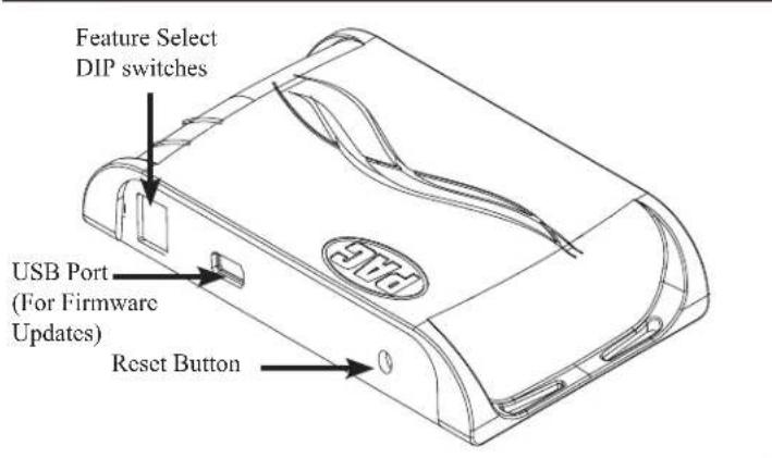

Installation
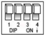
Set DIP switches to the ON position to activate the corresponding features. Set DIP switches to the OFF position for any features that are not desired. ***All DIP switches must remain in the off (up) position in order to set up the MCI with the PC

| DIP switches Blind Spot Camera Operation Front Camera Operation | ||
| All Off (up) PC Setup PC Setup | ||
| 1 on On with Turn Signal Off | ||
| 2 on On with Turn Signal On with Shift to Drive, then Off with MPH > 6 MPH or 30s | ||
| 1,2 on | On with Turn Signal and MPH > 0 | Off |
| 3 on | On with Turn Signal and MPH > 0 | On with Shift to Drive, then Off with MPH > 6 MPH or 30s |
| 1,3 on | On with Turn Signal and MPH > 20 | Off |
| 2,3 on | On with Turn Signal and MPH > 20 | On with Shift to Drive, then Off with MPH > 6 MPH or 30s |
| 1,2,3 on Double Tap Turn Signal Off | ||
| 4 on | Double Tap Turn Signal | On with Shift to Drive, then Off with MPH > 6 MPH or 30s |
| 2,3,4 on | Off | On with Shift to Drive, then Off with MPH > 6 MPH or 30s |
| All On (down) | Off | Off |
Installation (cont.)
- You can plug the MCI into a Windows PC and set up the blind spot and / or front camera operation using the app. See page 3 for more details on the app. OR
- Set DIP switches to the ON position that correspond with the features you want to add. The DIP switches must be set before connecting the interface to the vehicle harness. If you change the DIP switch settings with the power harness connected, you must disconnect and reconnect it for the changes to take effect.
- Remove the factory screen and disconnect the factory harness.
- Connect the factory harness into the black female connector on the MCI-FD22 harness.
- Connect the black male connector on the MCI-FD22 harness to the factory screen.
- Connect the video output of the VS41 harness to the input (female) side of the factory reverse camera wire located on the screen side of the MCI-FD22 harness.
- Connect the output (male) side of the factory reverse camera wire, located on the vehicle
side of the MCI-FD22 harness, to Input 1 on the VS41.
- If you are adding a front camera, connect it's video output to input 2 on the VS41 harness.
- If you are adding blind spot cameras, connect the left camera to input 3 and the right camera to input 4 on the VS41 harness.
- You can use the MCI-FD22 accessory output to power your cameras.
\*\*Steps 11-14 only necessary in the Ford Transit\*\*
- Run the Yellow / Black wire over to the steering column.
- Remove the steering column shroud and find the gray factory plug seen in Fig 1.
- Disconnect the factory harness, connect the male side of the MCI-FD22 harness to the steering column.
-
Connect the factory plug to the female side of the MCI-FD22 harness.
-
If you wish to use the on-demand activation feature, run and mount the toggle switch on the MCI-FD22 harness to your desired location. The on-demand toggle switch will allow you to view the front or reverse camera at any time.
- Connect the VS41 to the MCI.
- Connect both the MCI module and the VS41 to their respective harnesses.
- Turn the ignition on. LED1 should turn red.
- The module can be reset to factory default settings by pressing and holding the reset button (on the side of the module) for 5 seconds. When pressing and holding the button, both LEDs will blink red while the module is resetting. Once reset, LED1 will turn solid red.
Wiring Connection Chart

flowchart
graph TD
    A["To Vehicle Harness"] --> B["To Steering Column"]
    B --> C["MCI-FD22-HAR"]
    C --> D["To Screen"]
    D --> E["MCI-FD22"]
    E --> F["VS41"]
    F --> G["RIGHT CAMERA"]
    F --> H["FRONT CAMERA"]
    F --> I["REVERSE CAMERA INPUT"]
    F --> J["VIDEO OUTPUT"]
    F --> K["Data controlled camera switching cable (10-pin)"]
    style A fill:#f9f,stroke:#333
    style B fill:#f9f,stroke:#333
    style C fill:#ccf,stroke:#333
    style D fill:#ccf,stroke:#333
    style E fill:#cfc,stroke:#333
    style F fill:#cfc,stroke:#333
    style G fill:#fcc,stroke:#333
    style H fill:#fcc,stroke:#333
    style I fill:#fcc,stroke:#333
    style J fill:#fcc,stroke:#333
    style K fill:#fcc,stroke:#333
Follow the example above to make all inputs work accordingly through the one camera input on the factory radio. Connect the 10-pin harness from the VS41 harness into the Expansion Port on the MCI-FD22. Do not manually wire the trigger wires, or power and ground leads, when using the Expansion Port connector. When the appropriate CAN-Bus signals are detected (ie. reverse, or turn signal) the corresponding camera input will be automatically selected, and it's video feed will be routed to the factory radio display.
PAC App
PLEASE NOTE:
All DIP switches must be in the off (up) position in order to set up the MCI with the app. You can program the MCI either on the bench or in the car (with ignition on). To program the MCI module with the PAC app, follow these steps:
- Download and install the PAC app. It can be found online at www.aampglobal.com/downloads.
- Once installed, open the app.
- Connect the interface to the PC. PLEASE NOTE: All DIP switches must be in the up (off) position.
- When first connected, the revision info for both the app and the interface should be displayed.
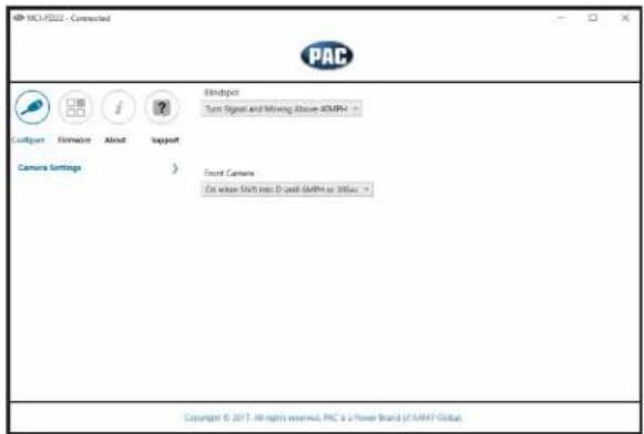
- Select "Configure". (Fig A).
- You may now choose "Camera Settings" on the left, then make selections within that category on the right (Fig B).
- Once all selections have been made, you can simply disconnect the interface and install it.
Fig A Fig B

Operation
The appropriate cameras will trigger according to how you have the interface setup. You can always force the front or reverse camera at any time by using the on-demand activation switch.
Brand : PAC
Model : MCI-FD22
Category : Air conditioner