
58170 - Tiller TORO - Free user manual and instructions
Find the device manual for free 58170 TORO in PDF.


| Brand | Toro |
| Model | 58170 |
| Product Type | Lawn Mower |
| Engine Type | Gasoline, 4-stroke |
| Cutting Width | 21 inches (53 cm) |
| Cutting Height Range | 1-4 inches (2.5-10 cm) |
| Wheel Size | Front: 8 inches; Rear: 10 inches |
| Fuel Tank Capacity | 0.5 gallons (1.9 L) |
| Weight | 75 lbs (34 kg) |
| Dimensions (L x W x H) | 55 x 22 x 38 inches (140 x 56 x 97 cm) |
| Start Type | Recoil start |
| Drive Type | Rear-wheel drive, self-propelled |
| Bag Capacity | 2.5 bushels (88 L) |
| Mulching Capability | Yes, with included plug |
| Side Discharge | Yes, with included chute |
| Blade Type | Standard steel blade |
| Maintenance Intervals | Oil change every 50 hours; sharpen blade annually |
| Safety Features | Blade brake, operator presence control |
| Warranty | 2 years limited |
Frequently Asked Questions - 58170 TORO
User questions about 58170 TORO
0 question about this device. Answer the ones you know or ask your own.
Ask a new question about this device
Download the instructions for your Tiller in PDF format for free! Find your manual 58170 - TORO and take your electronic device back in hand. On this page are published all the documents necessary for the use of your device. 58170 by TORO.
USER MANUAL 58170 TORO
To assure maximum safety, optimum performance, and to gain knowledge of the product, it is essential that you or any other operator of the tiller read and understand the contents of this manual before the engine is ever started. Pay particular attention to the SAFETY INSTRUCTIONS highlighted by this safety alert symbol —

The symbol means CAUTION, WARNING or DANGER — personal safety instruction. Failure to comply with the instruction may result in personal injury.

FOREWORD
The TORO Tiller has advanced concepts in engineering, design, and safety. If set-up and maintained properly, the tiller will give long, dependable service.
Since the tiller is a high-quality product, TORO is concerned about the future use of the tiller and safety of the user. Therefore, read this manual carefully to familiarize yourself with the safety instructions and the product before operating the tiller. The seven major sections of the manual are:
- Safety Instructions
- Set Up Instructions
- Before Operating
- Controls and Operating Instructions
- Maintenance
- Engine Operating and Maintenance Instructions
- Trouble Shooting
Note that safety, mechanical, and some general information in the manual is emphasized. The words CAUTION, WARNING, DANGER, IMPORTANT, and NOTE are used to classify the information. CAUTION, WARNING, and DANGER identify safety related information; and NOTE identifies general information worthy of special attention.
OPTIONAL SPARK ARRESTER
In some areas there are local, state or federal regulations requiring that a spark arrester be used on the engine of this tiller. If a spark arrester is required, order from your local Briggs & Stratton dealer.
Notice to customers in the State of California - The engine on this unit is NOT equipped with a spark arresting muffler.
WARNING
When tiller is used or operated on any California forest, brush or grass covered land, a working order spark arrester must be attached to muffler. If not, the operator is violating state law, Section 4442 Public Resources Code.
If help - concerning set-up, operation, maintenance, or safety - is ever needed, contact the local Authorized TORO Service Dealer or Distributor. Refer to the "Yellow Pages" for assistance. In addition to skilled service technicians, the dealer and distributor have other TORO products, as well as factory approved accessories and replacement parts. Keep your Toro Tiller all TORO. Buy genuine TORO replacement parts and accessories.
TABLE OF CONTENTS
Page
Safety Instructions 3
Before Operating 3
While Operating 3
Maintaining Tiller 3
Before Operating 4
Fill Crankcase With Oil 4
Fill Fuel Tank With Gasoline 4
Controls and Operating Instructions .... 4
Engine Throttle Control and Stop Lever .. 4
Handle Control Lever 4
Clutch Control Lever 4
Ground Speed Lever 5
Depth Control Lever 5
"Free Wheel" Control 5
Operating Suggestions 5
Starting and Stopping Instructions ..... 6
Tiller Maintenance 6
Adjustments:
Belt Adjustments 6
Page
Handle Control Lever Adjustment ..... 7
Clutch Control Lever Adjustment ..... 8
Lubrication:
Wheel Drive Case 8
Tine Drive Case 9
General 9
Belt Replacement 10
Storage 11
Engine Operating and Maintenance ..... 13
Before Starting 13
Starting 14
Maintenance 14
Adjustments 16
General Information 17
Storage 17
Trouble Shooting 18
Identification and Ordering 20
The Toro Promise 20

COPYRIGHT © ALL RIGHTS RESERVED
The Toro Company - 1982
MINNEAPOLIS, MN 55420 - U.S.A.
SAFETY INSTRUCTIONS

This safety alert symbol means CAUTION, WARNING or DANGER - "personal safety instruction". Read and understand the instruction because it has to do with safety. Failure to comply with the instruction may result in personal injury.
The following "Instructions for Safe Tilling" are suggested by The Toro Company. Failure to operate the tiller in accordance with these Safety Instructions MAY RESULT IN PERSONAL INJURY.
BEFORE OPERATING
- Read and understand the contents of this manual before starting and operating the tiller. Become familiar with all controls and know how to stop tiller quickly. NEVER ALLOW CHILDREN TO OPERATE TILLER.
- Keep everyone, especially children and pets, away from the area of operation. Remove glass, metal objects, sticks, stones, wire and any other debris that might get caught in or possibly be thrown by the tines.
- Keep all shields and safety devices in place. If shield, safety device or decal is defective, repair or replace it before operation is commenced. Also tighten any loose nuts, bolts and screws.
- Wear long pants and substantial shoes while using the tiller. Do not operate tiller while barefoot, wearing sandals, tennis shoes, sneakers or shorts.
- Fill fuel tank with gasoline before starting the engine. Avoid spilling any gasoline. Since gasoline is highly flammable, handle it carefully.
A. Use an approved gasoline container.
B. Fill tiller fuel tank outdoors when engine is cool. Engine must not be running to prevent a potential hazard.
C. Wipe up any gasoline that may have spilled, and install gasoline container cap and tiller fuel tank cap before starting the engine.
WHILE OPERATING
-
Open doors if engine will be run in the garage because exhaust fumes are dangerous and could possibly be deadly. Do not run engine indoors.
-
Do not operate the tiller if someone is near the area to be tilled.
- Tilling the soil demands attention. Always maintain secure footing, balance and control.
- Till the soil when it is dry or moist because wet or sticky soil can cause mechanical damage.
- Keep face, hands, feet and any other part of the body or clothing away from concealed, moving or rotating parts such as the tines, belts and pulleys. Stay behind the handles and away from the tines while operating the tiller.
- Release clutch control, shut engine off and wait for all parts to stop before removing any obstruction from the tines. Use a stick to remove the obstruction.
- If a solid object is hit by the tines or tines get plugged, release clutch control and shut engine off. Remove high tension wire from spark plug; then check for possible damage, an obstruction or loose parts. Use a stick to remove any obstruction, and make all repairs before using the tiller again.
- Before leaving the operator's position - behind handles - release clutch control and shut engine off. Pull high tension wire off spark plug to prevent possibility of accidental starting.
- Do not touch the engine while it is running or soon after it is stopped because the engine may be hot enough to cause a burn.
MAINTAINING TILLER
- Before performing any maintenance or servicing the tiller, shut engine off and pull high tension wire off spark plug to prevent possibility of accidental starting.
- Perform only those maintenance instructions described in this manual. If major repairs are ever needed or assistance is desired, contact an Authorized TORO Service Dealer.
- Keep tiller in safe operating condition by having nuts, bolts and screws tight.
- To reduce potential fire hazard, make sure engine and tiller chassis is free of excessive grease, vegetation, dirt and other foreign matter.
- Do not overspeed the engine by changing governor settings. Recommended engine speed is 3600 rpm. To assure safety and accuracy, have an Authorized TORO Service Dealer check maximum engine speed (3600 rpm) with a tachometer.
BEFORE OPERATING
- IMPORTANT: FILL CRANKCASE WITH OIL.
Before starting the engine, refer to the engine instructions in the engine section. Be certain that the engine crankcase is filled with the proper type oil and that all engine service instructions have been followed completely (see page 13).
- Fill fuel tank with a clean, fresh, low-lead or leaded "regular" grade of automotive gasoline. Do not use "gasohol". Do not mix oil with gasoline.
- All nuts and bolts should be checked and tightened during the first two (2) hours of use. Periodic checks should be made thereafter.
- The tires are normally over-inflated for shipping. The recommended tire pressure is 20 lbs.
CONTROLS
ENGINE CHOKE
See engine section, page 13.
ENGINE REWIND STARTER
See engine section, page 13.
ENGINE THROTTLE CONTROL AND STOP LEVER
This control regulates the engine speed from idle to fast and also stops the engine. (See Fig. 1 for location of control.) To idle engine pull throttle control back. To increase speed push throttle control forward. To stop engine pull throttle control all the way back.
HANDLE CONTROL LEVER
The handle control lever unlocks the handle so the operator may change the handle swing position and the handle height. The handle control lever is under the center of the handle panel (see Figure 1).
The handle has one (1) transport position (over the engine) and seven (7) tilling positions (over the tines). (Notice the locking notches where the handle pivot assembly, Fig. 2, attaches to your tiller frame.) In each of the (8) swing positions, three (3) handle heights are available.
To Adjust Handle Swing Position: Pull back on handle control lever and swing handle to the transport position or any one of the (7) tilling positions. Release the control lever and swing the handle back and forth slightly until handle locks in position. To Adjust Handle Height: Pull back on handle control lever; without swinging handle, raise or lower handle to desired height. Release control lever and move handle up and down slightly until handle locks in position. NOTE: When pulling back on the handle control lever, the clutch control lever is automatically moved to the neutral position. However, for easier operation, move clutch control lever to neutral position before pulling handle control lever.
The clutch control lever is a single lever that engages and disengages drive to both the tines and the wheels.

FIGURE 1
![graph TD A["Pivot Assembly"] --> B["Handle Swing"] B --> C["Tilling Location"] C --> D["Transport Location"] style A fill:#f9f,stroke:#333 style B fill:#ccf,stroke:#333 style C fill:#cfc,stroke:#333 style D fill:#fcc,stroke:#333](/content/2026/05/1083789/images/6f72614d08dbff4300dfe285d971ee3de47aa4652423ad8ede9f03f88ac30a11.jpg)
FIGURE 2
When the handle bar is in the tilling location, pushing forward on the control lever engages the drive to both the tines and the wheels at a tilling speed. CAUTION: Before pushing lever forward, be certain depth control setting is correct for soil conditions. (See "Depth Control Lever".)
Pulling back on clutch control lever from forward drive to neutral disengages the drive to the tines and wheels. Further pulling back on the lever engages the reverse drive to the wheels and the tiller moves backwards at transport speed. (Tines do not rotate in reverse.) When released, the control lever will return to neutral position.
When the handle bar is in transport location, the clutch control lever will only operate by pulling the lever back. This engages the drive to the wheels and the tiller moves forward at transport speed. When released, the control lever returns to neutral.
CONTROLS AND OPERATING INSTRUCTIONS
GROUND SPEED LEVER
The ground speed lever (Figure 1) controls the forward speed the tiller travels while tilling. It is located at the top-front section of the belt guard. The lever has five settings. The uppermost setting is for faster speed. The lowest setting is for slowest speed. The faster speeds are used in lighter soils and for cultivating while the slower speed is used in heavier soils and sod breaking.
DEPTH CONTROL LEVER

CAUTION: Do not adjust tilling depth with the tines rotating. Place clutch control lever in the neutral position before making adjustments of depth control.
The depth control lever, Fig. 3, is the "key" to easy tilling operation. The exact setting of control will vary with soil conditions. To Operate: Push lever forward then lift or lower to desired position.

CAUTION: If depth control is set too deep in hard or unworked ground, the tines will propel the tiller forward pushing the drive wheels along the ground at an uncontrolled speed.
When starting a tilling operation, start with the depth control lever in the shallowest setting (Figure 3). As you become acquainted with the soil, gradually raise the control lever (one notch at a time) so that deeper tilling can be done. This will prevent the uncontrolled forward speed that may occur if the depth control is set too deep too soon.
NOTE: On some models, the lowest notches on depth bar will not engage and are not intended to be used.
"FREE WHEEL" CONTROL
This control enables you to push the tiller easily. To "Free Wheel", pull klik pin out of wheel hub and axle and insert pin into the outer hole of the axle. This permits the wheels to turn freely about the axle. NOTE: Be sure the klik pins are replaced through the wheel hubs and inner holes on axle before operating tiller (see Illustration A).
OPERATING SUGGESTIONS
When you start to till in the garden, remember to take it easy. Do not try to take too deep a cut in a pass through sod or hard ground, or soil that has not been tilled for several months or years.
Do not lean on the handle bars because this takes weight off the front wheels, reduces traction, and causes the tines to attempt to propel the tiller instead of just digging.
There are several schools of thought as to the best method to till. It is suggested you try the various methods and select the one you are most comfortable with to get the results you desire.

FIGURE 3

Illustration A
A. On each succeeding pass, overlap one-half of the previous pass.
B. On the second pass, leave a 1/2 width untilled and till this width on the third pass. Repeat on the fourth pass, leaving a 1/2 width untilled and on the fifth pass, till the untilled strip.
C. Use A or B and repeat at 90 degrees.
Remember the key to easy tilling is the depth control setting. Do not try to take too deep a cut in harder soils.
CONTROLS AND OPERATING INSTRUCTIONS
STARTING THE TILLER
Now that you have located the controls and understand their operation and function, it is time to start your tiller.
- Move the tiller to suitable ground.
- Place clutch control lever in neutral.
- Pull throttle control to fast position.
- Adjust engine choke to proper position. (Refer to engine starting procedures in engine section, page 14.)
- Start engine by pulling starter cord.
NOTE: Allow engine a minute or two to warm up. (Open choke gradually as engine warms.) Operate tiller in forward and reverse, and in all settings of the ground speed control lever. Try all operating controls and various handle positions.
To Stop Engine
- Place clutch control lever in neutral position.
- Pull throttle control and engine stop lever to the stop position.
MAINTENANCE
ADJUSTMENTS

CAUTION: Never attempt to make adjustments on the tiller while the engine is running. Always stop the engine and disconnect the wire from the spark plug before attempting to make adjustment.
BELT ADJUSTMENTS
Belts which are not adjusted correctly can make the tiller difficult to shift or cause the tiller to jump out of gear during operation. Adjust belts as follows:
TINE DRIVE BELT
The tine drive belt, which is the innermost belt, is adjusted by loosening the clamp bolt located under the tine shield and loosening the front tine shield bolt (pivot bolt) and rotating the entire case and tine assembly (see Figure 4). Rotate the case forward to slacken belt and back to tighten belt. With the clutch control lever in neutral, the belt should be slack enough that the tines do not rotate. With the clutch control lever in forward drive position, the tine drive idler arm compression spring should be compressed 1/2 to 3/4 of an inch from the roll pin (see Figure 5).
REVERSE WHEEL DRIVE BELT
This belt is self-adjusted by a spring loaded idler pulley.
PRIMARY FORWARD DRIVE BELT
This belt is self-adjusted by a spring loaded idler pulley.

FIGURE 4

FIGURE 5
MAINTENANCE
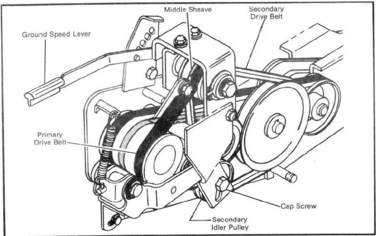
FIGURE 6
SECONDARY FOWARD DRIVE BELT
The secondary drive belt is the second belt from the outside, Figure 6. Check belt and adjust (if necessary) as follows:
- Place clutch control lever in neutral.
- Remove belt cover.
- Place ground speed lever in first forward (lowest) position.
- Pull sliding (middle) sheave, Figure 6, toward the outside as far as it will go. NOTE: To move middle sheave it may be necessary to slide primary drive belt up toward outside of groove, then slide middle sheave over.
- Move clutch control lever all the way forward.
IMPORTANT: Secondary drive belt should now be tight. If it is not, loosen cap screw on secondary idler pulley, Figure 6, slide pulley down until belt is tight, then retighten cap screw.
- Replace belt cover.
HANDLE CONTROL LEVER ADJUSTMENT
The handle control adjustment (Figure 7) has been set for proper operation and should not need to be adjusted. If the handle control lever (Figure 7) becomes loose after many hours of operation, tighten the adjustment nut only enough to eliminate any excess movement in the handle control lever.
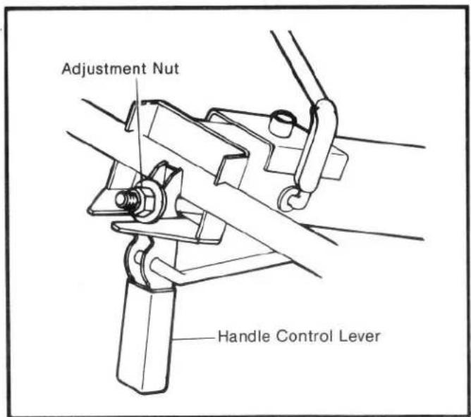
FIGURE 7

CAUTION: Do not overlighten adjustment nut. This may result in failure of handle bar latch system to fully engage and hold handle in desired position.
MAINTENANCE
CLUTCH CONTROL LEVER ADJUSTMENT
The clutch control lever is pre-set for neutral shift position. An adjustment means is provided, however, to center the clutch control lever in the slot on the handle shroud should it become necessary due to wear. This adjustment is located at the handle pivot point (Figure 8).
TO ADJUST:
- Place handle bar in tilling location and adjust handle bar to lowest position.
- Loosen the adjustment nut (Figure 8).
- Move the clutch control lever on the handle bar until centered in the neutral area (Figure 9).
- Retighten the adjustment nut (Figure 8).
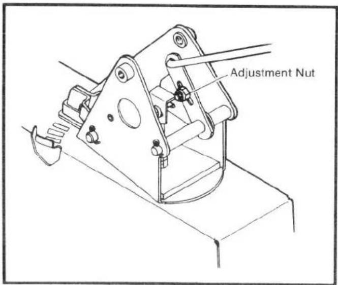
FIGURE 8
LUBRICATION
The best assurance you have of getting the most dependable service from your tiller is to keep the unit clean, free of rust, and well lubricated. Check bolts often to be sure they are kept tight. When the tiller is not being used, it should be stored in a dry place out of the weather.
IMPORTANT! Apply oil and grease carefully and only where required. Oil or grease on drive belts or pulleys will cause slippage and loss of drive. Wipe up all spills or excess oil and grease completely.
- Engine: Refer to engine section for operating instructions and lubrication requirements.
- Chain Cases: Both the wheel drive and the tine drive cases are amply filled with lubricant and should not require additional lubrication. If a leak develops, add (EP) SAE 140 heavy duty oil as required to bring to proper oil level. Check oil level every 25 hours.
The following procedure should be followed to check lubricant level of cases. When checking cases, do not drain excess lubricant out of the cases.
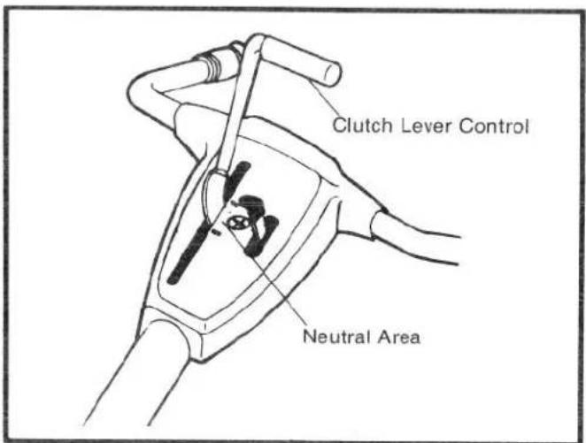
FIGURE 9
WHEEL DRIVE CASE
To check the oil level of the wheel drive case, place the depth control lever down to the shallowest setting (Figure 3). Remove the inspection plug on the right side of the wheel drive case (Figure 10). Case has sufficient oil if oil is up to bottom of inspection plug hole. It may be more convenient to remove the right wheel when checking this level.
If oil isn't up to bottom of hole, remove counter-weight for easier filling. Fill slowly with (EP) SAE 140 heavy duty oil until proper level is reached. Replace oil fill plug. Wipe off excess oil.

FIGURE 10
MAINTENANCE
TINE DRIVE CASE
To check the lubrication level of the tine drive case:
A. Set depth control at the deepest setting (Figure 3).
B. Place tiller on a level surface so that the tines and the wheels are setting on the ground, Figure 11B.
C. Wipe dirt away from oil level plug and remove plug. Figure 11A. Oil should be up to the bottom of hole.
D. If oil isn't up to bottom of hole, wipe dirt away from oil fill plug and remove, Figure 11B. Fill slowly with (EP) SAE 140 heavy duty oil until proper level is reached. Replace oil level plug and oil fill plug. Wipe off excess oil.
- The following points should be lubricated with engine oil every eight hours (see Figure 12). Before oiling clean off area to be lubricated.
A. The handle plunger shaft and disc.
B. The handle rotating surface.
C. Cam and detent ball and shaft.
D. Handle control lever.
E. General Lubrication: Apply oil to all pivot points and linkages to reduce wear and assure free movement.
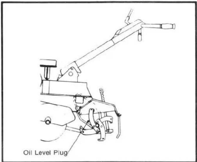
FIGURE 11A

FIGURE 11B

FIGURE 12
MAINTENANCE
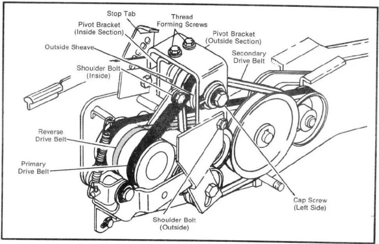
FIGURE 13
BELT REPLACEMENT - FIGURES 13 and 14
The belts on this tiller were specifically designed and engineered to provide long, trouble-free service. If belt replacement is required, order the required belt(s) from your Authorized TORO Service Dealer or Distributor, to be sure you have a belt that will provide the life and service required.
PRIMARY FORWARD DRIVE BELT
- Place clutch lever in neutral.
- Remove the belt guard.
- Unscrew the cap screw on left side of pivot bracket about 3/4 ". HINT: Wedge screwdriver between sheave and bracket to prevent sheave from turning while cap screw is being loosened.
- Remove inside shoulder bolt from bottom of pivot bracket.
- Remove the (2) thread forming screws from the top of the pivot bracket.
- Now lightly tap the left side cap screw with a hammer until shaft slides out of pivot bracket; then remove the cap screw and washers from shaft.
-
Place ground speed lever in lowest position then remove inside section of bracket with sheaves by sliding belts off of sheaves.
-
Remove outside section of bracket and speed lever by removing outside shoulder bolt.
-
Move clutch control lever into the "FORWARD" position.
-
Slip secondary belt off secondary idler pulley.
-
Slide primary drive belt off of engine pulley and forward idler pulley and through space between forward idler and left hand frame assembly. Now remove primary belt by sliding between secondary idler pulley and rubber reverse drive wheel.
-
Install new belt by reversing the removal procedure. NOTE: Follow these additional instructions when reassembling.
A. When reassembling pivot bracket be sure ground speed lever is ahead of the stop tab and in the lowest position. Also be sure shoulder bolts are inserted from the inside out (the heads of the bolts should face each other).
B. After belts are in place on sheaves, line up shaft with hole in pivot bracket and carefully draw shaft into place by reassembling and tightening the left side cap screw, lock washer and washer. (Hold cap screw on right side of shaft when tightening.)
NOTE: Be sure that key in shaft is engaged in both outside sheaves.
C. Be certain all belts are inside belt fingers and belt guide pins.
MAINTENANCE
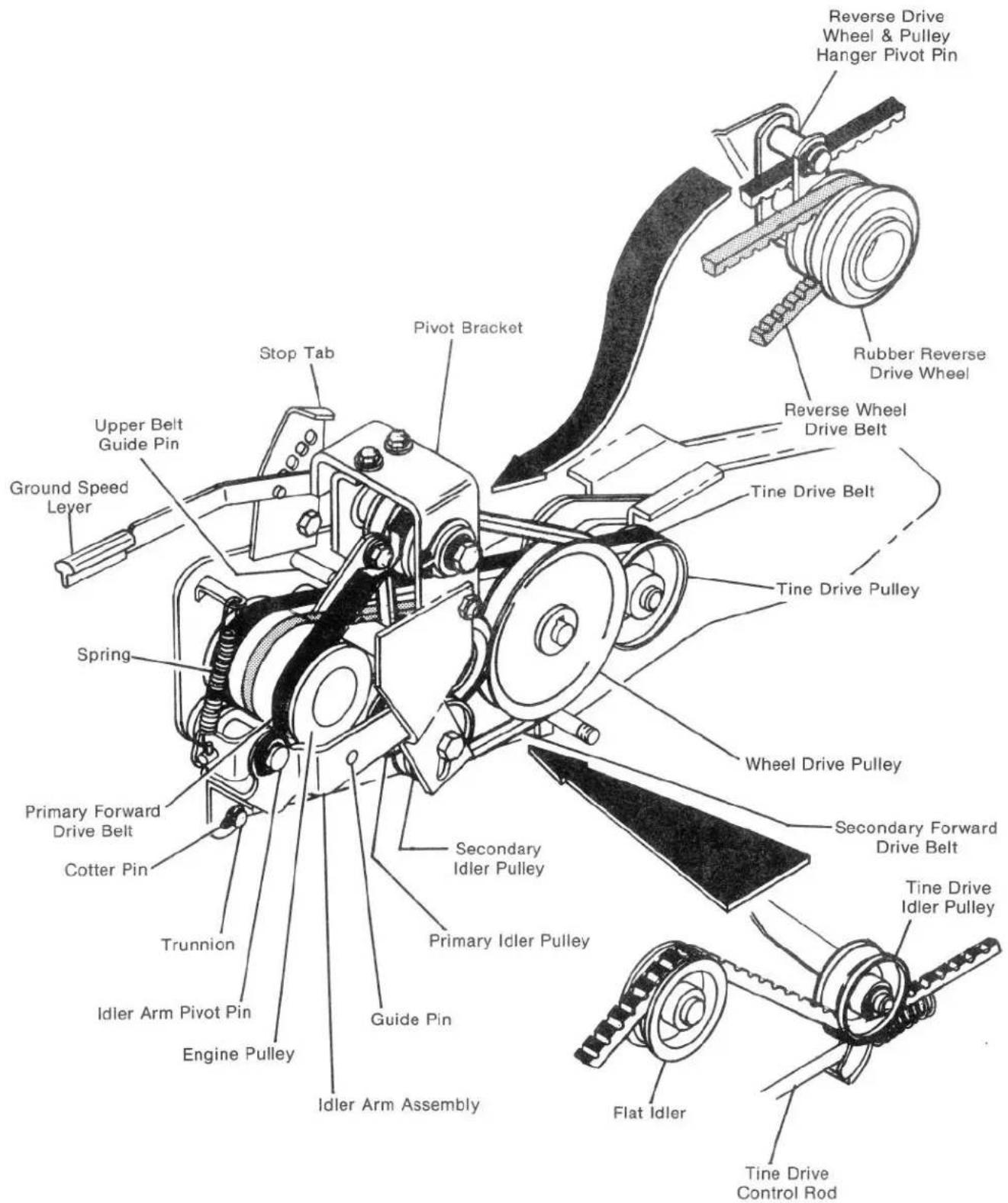
FIGURE 14
SECONDARY FORWARD DRIVE BELT
- Follow steps 1-8 under "Primary Drive Belt" replacement, then go to step 2 below.
- Remove secondary drive belt by sliding belt off of wheel drive pulley and secondary idler pulley then through space between secondary idler pulley and rubber reverse drive wheel.
- Reinstall belts by reversing the removal procedures. NOTE: Follow the additional instructions in step 12 under "Primary Foward Drive Belt".
- Readjust the belt as outlined under BELT ADJUSTMENTS - "Secondary Forward Drive Belt".
REVERSE WHEEL DRIVE BELT
- Remove primary and secondary belts. (See belt replacement instructions for each belt.)
- Unhook spring from idler arm assembly.
- Remove hair pin cotter holding trunnion to idler arm assembly.
- Remove retaining ring from idler arm pivot pin.
- Move clutch control lever to neutral position.
- Lift up reverse idlery pulley (not shown) to loosen belt then slide belt off of reverse idler pulley.
- Slide idler arm assembly off pivot pin.
- Slide belt off engine pulley.
- Remove belt by rolling belt between rubber reverse drive wheel and wheel drive pulley.
- Reinstall belts by reversing the removal procedures. NOTE: Follow the additional instructions in step 12 under "Primary Foward Drive Belt".
TINE DRIVE BELT
- Remove primary, secondary, and reverse wheel drive belts (see belt replacement instructions for each belt).
- Place clutch control lever in neutral position.
- Remove the retaining ring from the tine drive idler pulley shaft. Slide the tine drive idler pulley outward until belt can be removed.
- Slip belt off the tine drive pulley.
- Remove the retaining ring from the reverse drive wheel and pulley hanger pivot pin. Slide the hanger outward until the belt can be removed; remove belt from tiller.
- Reinstall belts by reversing the removal procedure. NOTE: Be sure tine drive belt runs over flat idler. Follow the additional instructions in step 12 under "Primary Foward Drive Belt".
- Readjust the belt as outlined under BELT ADJUSTMENTS - "Tine Drive Belt".
STORAGE
For short term storage, clean the tiller off and store in a dry place.
If tiller is not to be used for an extended period of time, service tiller completely and store it in a dry place.
- Refer to the engine instructions for engine storage instructions.
- Drain gasoline from fuel tank.
- Run engine until it stops.
- Cover exposed metal surfaces with a thin coat of engine oil.
- Lubricate per instructions under "Servicing and Maintenance".
- Before using the tiller again, check all lubrication points, fill fuel tank, and review operating and safety instructions in this operator's manual.
ENGINE OPERATING AND MAINTENANCE INSTRUCTIONS


BEFORE STARTING
Use a high quality detergent oil classified "For Service SF, SE, SD or SC." Detergent oils keep the engine cleaner and retard the formation of gum and varnish deposits. Nothing should be added to the recommended oil.
RECOMMENDED SAE VISCOSITY GRADES

* If not available, a synthetic oil may be used having 5W-20, 5W-30 or 5W-40 viscosity.
TO FILL CRANKCASE WITH OIL
Place engine level. Clean area around oil fill before removing oil fill plug.
OIL FILL PLUG Remove oil fill plug. Fill crankcase to point of overflowing. POUR SLOWLY. Capacity approximately 2¾ pints (1.3 liters). Replace oil fill plug.

FILL FUEL TANK
Use clean, fresh, "regulargrade leaded, low-lead or lead-free" gasoline. DO NOT MIX OIL WITH GASOLINE.
NOTE: The use of "lead-free" gasoline produces fewer combustion deposits, but may shorten valve life if carburetor adjustment is too lean.
ENGINE OPERATING AND MAINTENANCE INSTRUCTIONS STARTING
Start, store and fuel engine in a level position.
OPEN FUEL VALVE— Several turns on engines so equipped.

CHOKE ENGINE: Move lever as illustrated.
NOTE: A warm engine requires less choking than a cold engine.

THROTTLE CONTROL: Move throttle control to FAST position.

TO START ENGINE

DANGER: ALWAYS KEEP HANDS AND FEET CLEAR OF ROTATING MACHINERY.
Rewind Starter. Grasp starter handle as illustrated and pull out cord rapidly to overcome compression and prevent kickback. Repeat if necessary with choke opened slightly. When engine starts, open choke gradually.

TO STOP ENGINE
Move throttle control lever to "STOP" position.
MAINTENANCE

WARNING: TO PREVENT ACCIDENTAL STARTING when servicing the engine or equipment, always remove the spark plug or wire from the spark plug and insert in v-notch.

CHECK OIL LEVEL regularly - after each five hours of operation. BE SURE OIL LEVEL IS MAINTAINED.
CHANGE OIL after first five hours of operation. Thereafter change every 25 hours of operation. Drain oil while engine is warm, as follows:
- Clean area around oil fill plug.
- Carefully tip tiller forward until it is resting on the counter weights.
(continued on next page)
ENGINE OPERATING AND MAINTENANCE INSTRUCTIONS
CHANGE OIL (continued)
- Place oil pan directly under opening; remove oil plug and allow oil to drain completely.
- Lower tiller to level position and refill with new oil of proper grade (see oil chart in BEFORE STARTING section).
- Wipe up any spilled or excess oil and replace oil fill plug.

TO SERVICE AIR CLEANER "Oil Foam" Air Cleaner
Clean and re-oil foam element at three month intervals or every 25 hours, whichever occurs first.
NOTE: Service air cleaner more often under dusty conditions.
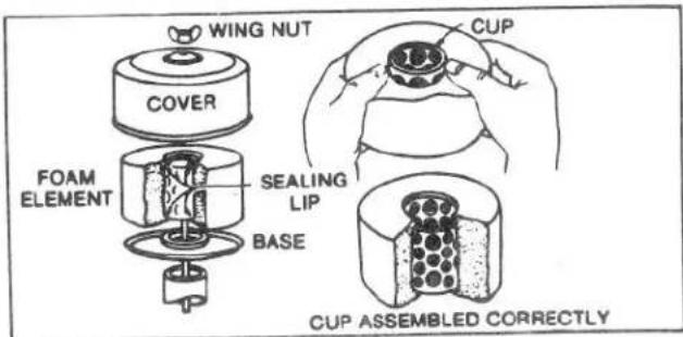
- Remove wing nut and cover.
- Remove air cleaner carefully to prevent dirt from entering carburetor.
- Take air cleaner apart and clean.
a. WASH foam element in kerosene or liquid detergent and water to remove dirt.
b. Wrap foam in cloth and squeeze dry.
c. Saturate foam with engine oil. Squeeze to remove excess oil. - Reassemble parts and fasten to carburetor.
CLEAN COOLING SYSTEM - Grass, chaff or dirt may clog the rotating screen and the air cooling system, especially after prolonged service. Yearly or every 100 hours, whichever occurs first, remove the blower housing and clean the areas shown to avoid overspeeding, overheating and engine damage. Clean more often if necessary.
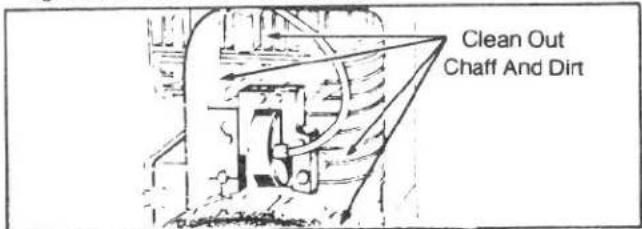

DANGER: Periodically clean muffler area to remove all grass, dirt and combustible debris.
SPARK PLUG - Clean and reset gap at .030" every 100 hours of operation.
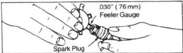
CAUTION: Do not blast clean spark plug. Spark plug should be cleaned by scraping or wire brushing and washing with a commercial solvent.
Sparking can occur if wire terminal does not fit firmly on spark plug. Reform terminal if necessary.
REMOVE COMBUSTION DEPOSITS every 100-300 hours of operation. Remove cylinder head and cylinder head shield. Scrape and wire brush the combustion deposits from cylinder, cylinder head, top of piston and around valves. Use a soft brush to remove deposits. Re-assemble gasket, cylinder head and cylinder head shield. Turn screws down finger tight with the three longer screws around the exhaust valve, if so equipped. Torque cylinder head screws in a staggered sequence to 140 inch pounds (15.82 Nm).
SPARK ARRESTER EQUIPPED MUFFLER - If engine muffler is equipped with spark arrester screen assembly, remove every 50 hours for cleaning and inspection. Replace if damaged.
CLEAN ENGINE - Remove dirt and debris with a cloth or brush. Cleaning with a forceful spray of water is not recommended as water could contaminate the fuel system.
FUEL FILTER — Replace IN-LINE filter or clean screen and bowl every season.

ENGINE OPERATING AND MAINTENANCE INSTRUCTIONS
ADJUSTMENTS
CARBURETOR ADJUSTMENTS
Minor carburetor adjustment may be required to compensate for differences in fuel, temperature, altitude or load.
NOTE: The air cleaner must be assembled to carburetor when running engine.
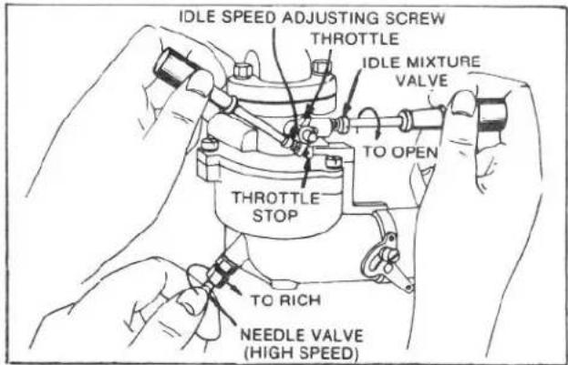
TO ADJUST CARBURETOR — Gently turn needle valve clockwise until it just closes. Valves may be damaged by turning them in too far.
Next, open the needle valve 1½ turns counterclockwise. This initial adjustment will permit the engine to be started and warmed up (approximately 5 minutes) prior to final adjustment.
FINAL ADJUSTMENT
Place governor speed control lever in "FAST" position. Turn needle valve in until engine slows (clockwise — lean mixture). Then turn it out past smooth operating point (rich mixture). Now turn needle valve to mid-point between rich and lean. Next, adjust idle RPM. Rotate throttle counterclockwise and hold against stop. Adjust idle speed adjusting screw to obtain 1750 RPM. Holding throttle against idle stop, turn idle valve in (lean) and out (rich). Set at midpoint between rich and lean. Recheck idle RPM. Release throttle. If engine will not accelerate properly, the carburetor should be re-adjusted, usually to a slightly richer mixture.
CONTROL ADJUSTMENTS
Proper speed control operation is dependent upon proper adjustment of speed controls on the powered equipment.
SPEED CONTROL ADJUSTMENT
The acceptable operating speed range is 1800 to 3600 RPM. Idle speed is 1750 RPM. DO NOT EXCEED 3600 RPM.
SPEED CONTROL
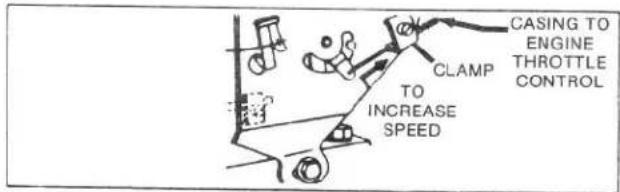
Engine throttle control should move governor speed control lever in direction illustrated to increase speed. Casing from engine throttle control is connected as shown. Wire travel is shown by arrows. NOTE: Clamp may be loosened and casing position adjusted, if necessary, to allow for full range of lever movement.
ENGINE OPERATING AND MAINTENANCE INSTRUCTIONS
GENERAL INFORMATION
These engines are single-cylinder L-head, air-cooled type.
MODEL SERIES 190400 and 195400
| Bore | 3" (76.2 mm) |
| Stroke | 2 3/4 " (69.85 mm) |
| Displacement | 19.44 cu. in. (318.5 cc) |
| Horsepower | 8.0 HP Max. @ 3600 RPM |
| Torque (Ft. Lbs.) | 12.7 Max. @ 2500 RPM |
The horsepower ratings listed are established in accordance with the Society of Automotive Engineers Test Code - J607. For practical operation, the horsepower loading should not exceed 85% of this rating. Engine power will decrease 3½% for each 1,000 feet (304.8 m) above sea level and 1% for each 10° above 60°F (16°C).
In some areas, local law requires the use of a resistor spark plug so as to suppress ignition signals. If an engine was originally equipped with a resistor spark plug, be sure to use the same type of spark plug for replacement.
TUNE-UP SPECIFICATIONS
| Spark Plug Type | Champion | Autolite | Robert Bosch |
| Short Plug | CJ-8 | 235 | WS9E |
| Long Plug | J-8 | 295 | -- |
| Resistor Short Plug | RCJ-8 | 245 | WSR9E |
| Resistor Long Plug | RJ-8 | 306 | -- |
| Spark Plug Gap | .030" (.76 mm) |
| Intake Valve Clearance | .005" - .007" (.13 - .18 mm) |
| Exhaust Valve Clearance | .009" - .011" (.23 - .28 mm) |
STORAGE INSTRUCTIONS
Engines to be stored over 30 days should be completely drained of fuel to prevent gum deposits forming on essential carburetor parts, fuel filter and tank.
NOTE: The use of a fuel additive, such as STA-BIL, or an equivalent, will minimize the formation of fuel gum deposits during storage. Such an additive may be added to the gasoline in the fuel tank of the engine, or to the gasoline in a storage container.
a. All fuel should be removed from the tank. Run the engine until it stops from lack of fuel. The small amount of fuel that remains in the sump of the tank should be removed by absorbing it with a clean, dry cloth.
b. While engine is still warm, drain oil from crankcase. Refill with fresh oil.
c. Remove spark plug, pour approximately one ounce (30 cc) of engine oil into cylinder and crank slowly to distribute oil. Replace spark plug.
d. Clean dirt and chaff from cylinder, cylinder head fins, blower housing, rotating screen and muffler areas.
e. Store in a clean and dry area.
TROUBLE SHOOTING
| Problem | Possible Causes | Corrective Action |
| Engine does not start. | 1. Gas tank is empty.2. Choke arm not in FULL position.3. Spark plug loose.4. High tension wire loose or disconnected from spark plug.5. Spark plug gap is incorrect.6. Spark plug is defective.7. Faulty points or condenser. | 1. Fill fuel tank with gasoline: Refer to Fill Fuel Tank, page 13.2. Move choke to FULL CHOKE position: Refer to Starting and Stopping Instructions, page 14.3. Tighten spark plug to 15 ft.-lb. (20.4 Nm)4. Install high tension wire on spark plug.5. Set gap between electrodes at 0.030 of an inch (0.76 mm).6. Install new, correctly gapped plug: Refer to Tune-Up Specifications, page 17.7. Contact Authorized TORO Service Dealer. |
| Engine starts hard or loses power. | 1. Dirt, water, or stale fuel in gas tank.2. Vent hole in fuel tank cap is plugged.3. Air cleaner is dirty. | 1. Drain gas and clean fuel tank. Fill tank with clean, fresh gasoline: Refer to Fill Fuel Tank, page 13.2. Clean or replace fuel tank cap.3. Clean the air cleaner element: Refer to To Service Air Cleaner, page 15. |
| Engine operates erratically. | 1. Spark plug is defective.2. Spark plug is gapped incorrectly.3. Air cleaner is dirty. | 1. Install new, correctly gapped plug: Refer to Tune-Up Specifications, page 17..2. Set gap between electrodes at 0.030 of an inch (0.76 mm).3. Clean the air cleaner element: Refer to To Service Air Cleaner, page 15. |
TROUBLE SHOOTING
| Problem | Possible Causes | Corrective Action |
| Engine idles poorly. | 1. Air cleaner is dirty.2. Oil level in crankcase is low.3. Air slots in engine shroud are plugged.4. Cooling fins and air passages under engine blower housing are plugged.5. Improper idle adjustment. | 1. Clean the air cleaner element: Refer to To Service Air Cleaner, page 15.2. Add oil to crankcase: Refer to Fill Crankcase With Oil, page 13.3. Remove obstruction from slots.4. Remove obstruction from cooling fins and blower housing: Refer to Clean Cooling System, page 15.5. Adjust carburetor properly, page 16. |
| Engine misfires at high speed. | 1. Air gap between electrodes of spark plug is too close.2. Carburetor adjusted incorrectly. | 1. Set air gap at 0.030 of an inch (0.76 mm).2. Adjust carburetor: Refer to Carburetor Adjustments, page 16. |
| Engine overheats. | 1. Cooling air flow is restricted.2. Oil level in crankcase is low.3. Incorrect spark plug. | 1. Remove any obstruction from slots in shroud, blower housing, air passages and cooling fins on engine.2. Add oil to crankcase: Refer to Fill Crankcase With Oil, page 13.3. Install Champion RCJ8 spark plug that is gapped at 0.030 of an inch. |
| Tiller vibrates abnormally. | 1. Tine section is loose.2. Engine mounting bolts are loose.3. Improper carburetor adjustment.4. Air cleaner plugged. | 1. Secure tine section with clevis pin and hair pin cotter.2. Tighten engine mounting bolts.3. Adjust carburetor properly, page 16.4. Service air cleaner, page 15. |
| Tines do not rotate. | 1. Belt is broken.2. Belt is adjusted incorrectly. | 1. Contact Authorized TORO Service Dealer.2. Adjust drive clutch belt: Refer to Belt Adjustments, page 6. |
IDENTIFICATION AND ORDERING
MODEL AND SERIAL NUMBERS
The tiller has two identification numbers: a model number and a serial number. The two numbers are stamped on a decal which is on the back of the tiller above the tine shield.
Record the model and serial numbers below and keep this manual in a safe place for future reference.
Model No.
Serial No.
In any correspondence concerning the tiller, supply the model and serial numbers to assure that correct information and replacement parts are obtained.
To order replacement parts from an Authorized TORO Service Dealer, supply the following information:
- Model and serial numbers of the tiller.
- Part number, description, and quantity of part(s) desired.
NOTE: Do not order by reference number if a parts catalog is being used; use the PART NUMBER.
The Toro Promise
A ONE YEAR LIMITED WARRANTY
The Toro Company promises to repair any TORO Product if defective in materials or workmanship. The following time periods from the date of purchase apply:
Residential Product 1 Year
Residential Products Used Commercially . . . 45 Days
The costs of parts and labor are included, but the customer pays the transportation costs. Just return any residential product to an Authorized TORO Service Dealer or TORO Distributor.
Should you feel your TORO Product is defective and wish to rely on The Toro Promise, the following procedure is recommended:
- Contact any Authorized TORO Service Dealer, TORO Master Service Dealer, or TORO Distributor (the Yellow Pages of your telephone directory is a good reference source).
- He will either instruct you to return the product to him or recommend another Authorized TORO Service outlet which might be more convenient.
- Bring the product along with your original sales slip, or other evidence of purchase date, to the service dealer.
- The servicing dealer will inspect the unit, advise you whether the product is defective and, if so, make all repairs necessary to correct the defect without extra charge to you.
If for any reason you are dissatisfied with the dealer's analysis of the defect or the service performed, you may contact us.
Write:
TORO Consumer Service Department
8111 Lyndale Avenue South
Minneapolis, Minnesota 55420
The above remedy of product defects through repair by an Authorized TORO Service Dealer is the purchaser's sole remedy for any defect.
THERE IS NO OTHER EXPRESS WARRANTY. ALL IMPLIED WARRANTIES OF MERCHANTABILITY AND
FITNESS FOR USE ARE LIMITED TO THE DURATION OF THE EXPRESS WARRANTY.
Some states do not allow limitations on how long an implied warranty lasts, so the above limitation may not apply to you.
This warranty applies only to parts or components which are defective and does not cover repairs necessary due to normal wear, misuse, accidents, or lack of proper maintenance. Regular, routine maintenance of the unit to keep it in proper operating condition is the responsibility of the owner.
All warranty repairs reimbursable under The Toro Promise must be performed by an Authorized TORO Service Dealer using Toro approved replacement parts.
Repairs or attempted repairs by anyone other than an Authorized TORO Service Account are not reimbursable under The Toro Promise. In addition, these unauthorized repair attempts may result in additional malfunctions, the correction of which is not covered by warranty.
THE TORO COMPANY IS NOT LIABLE FOR INDIRECT, INCIDENTAL OR CONSEQUENTIAL DAMAGES IN CONNECTION WITH THE USE OF THE PRODUCT INCLUDING ANY COST OR EXPENSE OF PROVIDING SUBSTITUTE EQUIPMENT OR SERVICE DURING PERIODS OF MALFUNCTION OR NON-USE.
Some states do not allow the exclusion or limitation of incidental or consequential damages, so the above limitation or exclusion may not apply to you.
This warranty gives you specific legal rights, and you may also have other rights which vary from state to state.
- FOREWORD
- OPTIONAL SPARK ARRESTER
- WARNING
- TABLE OF CONTENTS
- SAFETY INSTRUCTIONS
- BEFORE OPERATING
- WHILE OPERATING
- MAINTAINING TILLER
- CONTROLS
- ENGINE CHOKE
- ENGINE REWIND STARTER
- ENGINE THROTTLE CONTROL AND STOP LEVER
- HANDLE CONTROL LEVER
- CONTROLS AND OPERATING INSTRUCTIONS
- GROUND SPEED LEVER
- DEPTH CONTROL LEVER
- FREE WHEEL" CONTROL
- OPERATING SUGGESTIONS
- STARTING THE TILLER
- TO STOP ENGINE
- MAINTENANCE
- ADJUSTMENTS
- BELT ADJUSTMENTS
- TINE DRIVE BELT
- REVERSE WHEEL DRIVE BELT
- PRIMARY FORWARD DRIVE BELT
- SECONDARY FOWARD DRIVE BELT
- HANDLE CONTROL LEVER ADJUSTMENT
- CLUTCH CONTROL LEVER ADJUSTMENT
- TO ADJUST
- LUBRICATION
- WHEEL DRIVE CASE
- TINE DRIVE CASE
- BELT REPLACEMENT - FIGURES 13 AND 14
- SECONDARY FORWARD DRIVE BELT
- STORAGE
- ENGINE OPERATING AND MAINTENANCE INSTRUCTIONS
- BEFORE STARTING
- TO FILL CRANKCASE WITH OIL
- FILL FUEL TANK
- ENGINE OPERATING AND MAINTENANCE INSTRUCTIONS STARTING
- TO START ENGINE
- CHANGE OIL (CONTINUED)
- TO SERVICE AIR CLEANER "OIL FOAM" AIR CLEANER
- CARBURETOR ADJUSTMENTS
- FINAL ADJUSTMENT
- CONTROL ADJUSTMENTS
- SPEED CONTROL ADJUSTMENT
- SPEED CONTROL
- GENERAL INFORMATION
- STORAGE INSTRUCTIONS
- IDENTIFICATION AND ORDERING
- MODEL AND SERIAL NUMBERS
- THE TORO PROMISE
Brand : TORO
Model : 58170
Category : Tiller