DCV-11C - Voltmeter ENTES - Free user manual and instructions
Find the device manual for free DCV-11C ENTES in PDF.


| Product Type | DC Voltage Monitor |
| Model | DCV-11C |
| Brand | ENTES |
| Power Supply | 10-56 V DC |
| Power Consumption | <4 VA (supply) + <1 VA (measuring) |
| Measuring Range | ±200 V DC |
| Accuracy | 0.5% ±1 digit (10% to 100% of full scale) |
| Display | 2.5-inch backlit LCD |
| Measurement Period | 1-600 seconds (adjustable) |
| Alarm Outputs | 2 programmable relays (NO, 5A, 1250 VA) |
| Alarm Modes | High, Low, Range (High-Low), with hysteresis, delays, trip, latch |
| Security | 4-digit password protection |
| Input Resistance | <2 MΩ |
| Operating Temperature | -20 to 70 °C |
| Dimensions (Panel Cutout) | 48 x 96 mm (flush mount) |
| Weight | 0.240 kg |
| Enclosure Protection | IP40 (front), IP00 (terminals) |
| Installation Category | Class III |
| Standards | EN 61010-1, EN 61000-4-2, EN 61000-4-4, EN 61000-4-5, EN 61000-4-8, EN 61000-4-11 |
| Wire Width | 2.5 mm² |
| Fuse | 1A F-type |
| Languages | Turkish, English, German, French, Spanish |
| Backlight | Configurable (off, always on, 30s, 60s, 5min, 15min) |
| Contrast Adjustment | 0-15 steps |
Frequently Asked Questions - DCV-11C ENTES
User questions about DCV-11C ENTES
0 question about this device. Answer the ones you know or ask your own.
Ask a new question about this device
Download the instructions for your Voltmeter in PDF format for free! Find your manual DCV-11C - ENTES and take your electronic device back in hand. On this page are published all the documents necessary for the use of your device. DCV-11C by ENTES.
USER MANUAL DCV-11C ENTES
-Disconnect all power before connecting the device.
-Don't remove the front panel while the device is connected to the network.
-Don't clean the device with solvent or similar substances. Only clean with a dry cloth.
-Verify correct terminal connections when wiring.
-Electrical devices should be serviced only by your component seller.
-Device is for rack panel mounting only.
-Fuse which will be used must be F type and its current limit value must be 1A.
-No responsibility is assured by the manufacturer or any of its subsidiaries for any problems arising out of the disregard of these conditions.
SECURITY

Read the user manual completely before using the device.
The box is under dangerous high voltage. The device must be installed and serviced only by a qualified service personnel.
Displayed only when limit is crossed in opposite direction.

If a voltage higher than 200V or lower than -200V is applied to the measuring input of the device, a warning is displayed like the one on the left.
Is not displayed when limit is crossed in opposite direction.
Note: This manual is valid from Rev.2.00.00 firmware.
(Devices including INFO menu)
Warnings
- Connect a button or a circuit breaker between the grid and the supply inputs of the device.
- This button or circuit breaker must be in close proximity of the device.
- This button or circuit breaker must be marked to indicate that it is used to separate the device from the grid.
Standards That Are Applied To The Device
EN 61010-1, EN 61000-4-2, EN 61000-4-4, EN 61000-4-5, EN 61000-4-8, EN 61000-4-11
Guarantee
The device has a 2 year guarantee. In case of a malfunction, repairs of the device must be done only by the authorised technical service or the guarantee will be void.
Index
- INTRODUCTION....4
1.1. APPLICATIONS....4
1.2. GENERAL FEATURES....4
1.3. FRONT PANEL 5
1.4. HARDWARE FEATURES....8
- USAGE OF DEVICE 8
2.1. MENU USAGE AND SETTINGS....8
2.2. MAIN MENUS....8
2.2.1. PERIOD SETTING MENU....10
2.2.2.ALARMS MENU....10
2.2.3. ANALOG OUTPUT SETTING MENU....18
2.2.4.RS-485 SERIAL COMMUNICATION SETTING MENU....20
2.2.5. RESET MENU 24
2.2.6. DISPLAY SETTING MENU 26
2.2.7. LANGUAGE SETTING MENU....27
2.2.8. FACTORY SETTING MENU....28
2.2.9. SECURITY SETTING MENU....29
2.2.10.INFO MENU....30
2.2.11. EXITING MAIN MENU 31
- INSTALLATION....31
3.1. DIMENSIONS AND INSTALLATION....31
3.2. CONNECTION DIAGRAM....32
3.3. PC CONNECTION....33
4. FACTORY DEFAULT VALUES 34
5. TECHNICAL FEATURES....36
6. REGISTER TABLE....38
7. MENU MAP 46
1. INTRODUCTION
1.1 APPLICATIONS:
You can achieve the following measurements and applications with the device.
- All measured parameters can be transferred via RS485 line with MODBUS protocol and menus can be set remotely. (DCV-10S/10CS/11S/11CS)
- With 2 programmable Alarm Relays, a range in which the monitored system voltage should resice can be determined and a warning signal can be created for the user with Alarm1 (C1) and Alarm2 (C2) contact outputs if this monitored voltage goes out of the determined range. (DCV-10C/10CS/11C/11CS) - With a programmable Analog Output, the device can be programmed to give a voltage or current output according to the measured voltage value. (DCV-10A/11A)
- Measured maximum-minimum values can be monitored by using UP/DOWN buttons.
- Settings can be accessed easily and read comfortably with the back-lit LCD feature.
- Measurement results can be calculated in a desired time with an adjustable measurement period of 1-600 s.
- The device provides flexible usage with wide supply voltage range. 85-265 V AC/DC (DCV-10/10A/10C/10S/10CS), 10-56V DC (DCV-11/11A/11C/11S/11CS)
- The device settings can be protected from changes by unauthorized personnel by specifying a 4 digit user password.
1.2 GENERAL FEATURES
The device is designed to measure the voltage on a DC system.
1.3 FRONT PANEL
The device has a back-lit 2.5" LCD which contains two lines as numeric and alpha-numeric, warning symbols and notification signs. There are three buttons for programming the device. Explanations about the display and buttons are listed on the right side.

5
Usage of Front Panel and Buttons
-
Up button
-
Set button, for entry to menu and value entry
-
Down button
-
Indicates that the password protection is active.
-
Indicates the existence of communication. It blinks during communication. (DCV-10S/10CS/11S/11CS)
-
The line where measured parameters are displayed.
-
Indicates the direction of the measured voltage.
-
Indicates the notification messages or the menu where the user is.
-
Units belonging to measurements and analog output parameters
10.Indicates that the contact or contacts are in a high fault state. (DCV-10C/10CS/11C/11CS)
11.Indicates that the contact or contacts are in a low fault state.(DCV-10C/10CS/11C/11CS)
-
1st Contact Output (DCV-10C/10CS/11C/11CS)
-
2nd Contact Output (DCV-10C/10CS/11C/11CS)
14&15. Indicates that the contacts are closed.(DCV -10C/10CS/11C/11CS)
6
Special Functions for Buttons
UP button: It helps you display maximum voltage value during measurement. In programming mode, it is used to switch device parameters. If lock function is active, it enables alarm output contacts when tension value exceeds the configured threshold. When the tension is between the set limits, alarm output contacts are not turned off (locked-hold). When pressed together with DOWN button (UP + DOWN), output switches are turned off.
SET button: 3 seconds. When you hold down this button, MAIN MENU mode is activated. It is used to switch from MAIN MENU to SUB MENUS and to save parameter changes.
DOWN button: It helps you display minimum voltage value during measurement. In programming mode, it is used to switch device parameters. If lock function is active, it enables alarm output contacts when tension value exceeds the configured threshold. When the tension is between the set limits, alarm output contacts are not turned off (locked-hold). When prassed together with UP button (UP + DOWN), output switches are turned off.
1.4 HARDWARE FEATURES
- Voltage measurement connector (2-pin, V+, V-)
- 0/2-10V, 0-4/20 mA Analog Output connector (3-pin, V, GND, I)(DCV-10A/11A)
- RS-485 connector (4-Pin)(DCV-10S/10CS/11S/11CS)
- 2 Relay connectors (4-pin)(DCV-10C/10CS/11C/11CS)
- Supply input (2-pin) (85-265V AC/DC (DCV-10/10A/10C/10S/10CS), 10-56V DC (DCV-11/11A/11C/11S/11CS))
2- USAGE OF DEVICE:
2.1 MENU USAGE AND SETTINGS:
After the device is installed according to the connection diagram in the user manual, energize the device.(Refer to: Connection diagram) In order for the measurements and applications to be accurate, necessary adjustments must be made by using menus.
2.2 MAIN MENUS:
There are 11 main menus on the device for measurement and usage settings. The user can access MAIN MENUs by pressing the SET button for 3 seconds on measurement screen. By pressing the SET button on any MAIN MENU, SUB MENUs of the related MAIN MENU is entered.
MAIN MENU FLOW:
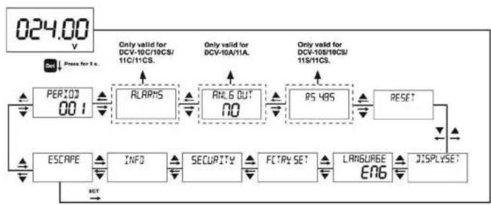
flowchart
graph TD
    A["024.00 V"] --> B["PERIOD 00.1"]
    B --> C["ALARM5"]
    C --> D["ANL6 OUT 00"]
    D --> E["RS 485"]
    E --> F["RESET"]
    F --> G["LANGUAGE ENG"]
    G --> H["DISPLAYSET"]
    H --> I["ESCRIPT"]
    I --> J["INFO"]
    J --> K["SECURITY"]
    K --> L["FCTRY SET"]
    L --> M["RESET"]
    M --> N["Only valid for DCV-10C/10CS/11C/11CS."]
    N --> O["Only valid for DCV-10A/11A."]
    O --> P["Only valid for DCV-10B/10CS/11S/11CS."]
    P --> Q["Only valid for DCV-10B/10CS/11S/11CS."]
    Q --> R["Only valid for DCV-10B/10CS/11S/11CS."]
    R --> S["Only valid for DCV-10B/10CS/11S/11CS."]
    S --> T["Only valid for DCV-10B/10CS/11S/11CS."]
    T --> U["Only valid for DCV-10B/10CS/11S/11CS."]
    U --> V["Only valid for DCV-10B/10CS/11S/11CS."]
    V --> W["Only valid for DCV-10B/10CS/11S/11CS."]
    W --> X["Only valid for DCV-10B/10CS/11S/11CS."]
    X --> Y["Only valid for DCV-10B/10CS/11S/11CS."]
    Y --> Z["Only valid for DCV-10B/10CS/11S/11CS."]
    Z --> AA["Only valid for DCV-10B/10CS/11S/11CS."]
    AA --> AB["Only valid for DCV-10B/10CS/11S/11CS."]
    AB --> AC["Only valid for DCV-10B/10CS/11S/11CS."]
    AC --> AD["Only valid for DCV-10B/10CS/11S/11CS."]
    AD --> AE["Only valid for DCV-10B/10CS/11S/11CS."]
    AE --> AF["Only valid for DCV-10B/10CS/11S/11CS."]
    AF --> AG["Only valid for DCV-10B/10CS/11S/11CS."]
    AG --> AH["Only valid for DCV-10B/10CS/11S/11CS."]
    AH --> AI["Only valid for DCV-10B/10CS/11S/11CS."]
    AI --> AJ["Only valid for DCV-10B/10CS/11S/11CS."]
    AJ --> AK["Only valid for DCV-10B/10CS/11S/11CS."]
    AK --> AL["Only valid for DCV-10B/10CS/11S/11CS."]
    AL --> AM["Only valid for DCV-10B/10CS/11S/11CS."]
    AM --> AN["Only valid for DCV-10B/10CS/11S/11CS."]
    AN --> AO["Only valid for DCV-10B/10CS/11S/11CS."]
    AO --> AP["Only valid for DCV-10B/10CS/11S/11CS."]
    AP --> AQ["Only valid for DCV-10B/10CS/11S/11CS."]
    AQ --> AR["Only valid for DCV-10B/10CS/11S/11CS."]
    AR --> AS["Only valid for DCV-10B/10CS/11S/11CS."]
    AS --> AT["Only valid for DCV-10B/10CS/11S/11CS."]
    AT --> AU["Only valid for DCV-10B/10CS/11S/11CS."]
    AU --> AV["Only valid for DCV-10B/10CS/11S/11CS."]
    AV --> AW["Only valid for DCV-10B/10CS/11S/11CS."]
    AW --> AX["Only valid for DCV-10B/10CS/11S/11CS."]
    AX --> AY["Only valid for DCV-10B/10CS/11S/ 585"]
2.2.1 "PERIOD" Period Setting Menu
After the device samples for a specified time, it displays the measurement result by calculating the mean value of those samples. You can set the sampling time in this menu. Period value can be entered between 1-600 seconds.

2.2.2 "ALARMS" Alarms Menu
DCV -10C/10CS/11C/11CS devices have two normally open (NO) contact outputs. Operating modes of the alarms are set in this menu. Each alarm can be set to one of six operating modes. These modes are high alarm, low alarm, high-low (range) alarm and their 3 inverted counterpart modes. This menu has 2 sub-menus.
"ALARM1", "ALARM2"

flowchart
graph TD
    A["RL ARMS"] -->|SET| B["RL ARM 1"]
    B --> C["RL ARM 2"]
    C --> D["BAC to MENU"]
    D -->|SET| B
    B -->|↓| E["↓"]
    C -->|↓| F["↓"]
    D -->|↓| G["↓"]
"ALARM1"Alarm 1 Setting Menu
Operating mode of the relay on the device and the parameter according to that operating mode is set in this menu. All settings belonging to 1. Alarm relay is done in this menu. Settings belonging to 2. Alarm relay can be done in "ALARM2" menu. This menu has 1 sub-menu.

"ALRM STAT" Alarm Status Setting Menu
Alarm function of the relay is activated in this menu. If "OFF" option is selected in this menu, alarm parameters of the corresponding relay can't be accessed. If the alarm function will be used, "ALRM STAT" option must be set as "ON" in this menu. When alarm status is set as "ON", the 4 sub-menus of this menu become accessible. These menus are "CONTACT POS", "ALRM TYPE", "TRIP" and "LATCH" menus.

flowchart
graph TD
    A["ALRM STAT OFF"] --> B["SET"]
    B --> C["OR"]
    C --> D["OR"]
    D --> E["CONTACT POS OFF"]
    E --> F["TRIP NO"]
    F --> G["LATCH NO"]
    G --> H["ALRM TYPE HIGH"]
    H --> I["BRACH MENU SET"]
    I --> J["SET"]
    J --> K["OR"]
    K --> L["OR"]
    L --> M["OR"]
    M --> N["OR"]
    N --> O["OR"]
    O --> P["OR"]
    P --> Q["OR"]
    Q --> R["OR"]
    R --> S["OR"]
    S --> T["OR"]
    T --> U["OR"]
    U --> V["OR"]
    V --> W["OR"]
    W --> X["OR"]
    X --> Y["OR"]
    Y --> Z["OR"]
11
"CONTACT POS" Contact Position Setting Menu
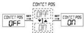
The starting position of the alarm relay output is set in this menu. If this option is selected as "OFF", contact output starts as open when there isn't a fault condition. If this option is selected as "ON", contact output will be closed when there isn't a fault condition. It is set "OFF" as factory default.
"TRIP"
If the measured voltage value becomes more than 1.5 times of set maximum voltage value when the "TRIP" function is selected as "YES", related alarm contact will open without a delay. In this case, up segment on the LCD and the dot in the C1 segment turn on. If the measured voltage value becomes less than 0.5 times of set minimum voltage value, related alarm contact will open without a delay. In this case, down segment on the LCD and the dot in the C1 segment turn on.

12
"LATCH"
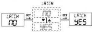
When the latch function is selected as "YES", a predefined alarm contact will open in case an alarm state arises. When the alarm state is resolved, the contact remains open (It latches). To close the alarm outputs after the alarm state is resolved, UP and DOWN button are pressed at the same time. When the latch function is selected as "NO", the opened alarm output will close after the predefined delay time.
"ALRM TYPE" Alarm Type Setting Menu
Operating mode of the alarm is set in this menu. Alarm has 3 operating modes which are High, Low and Range (High-Low).

flowchart
graph LRPH_TYPE_H 19H --> SET["SET"]
    SET --> RLPH_TYPE_LO["RLPH TYPE LO"]
    style RLPH_TYPE_H 19H fill:#f9f,stroke:#333
    style RLPH_TYPE_LO fill:#ccf,stroke:#333
When the alarm type is selected as High Alarm, first contact output opens after an on-delay time ("H ON DEL") if the measured voltage becomes more than the entered maximum voltage value ("HGH VALUE") and immediate opening option is inactive. In this case, up segment on the LCD and the dot in the C1 segment turn on. When the measured voltage drops below the set maximum value ("HGH VALUE") as much as the high hysteresis value ("HIGH HYS") and immediate opening option is inactive, first output contact closes after an off-delay time ("H OFF DEL"). In this case, up segment on the LCD and the dot in the C1 segment turn off.
When the alarm type is selected as Low Alarm, first contact output opens after an on-delay time ("L ON DEL") if the measured voltage becomes less than the entered minimum voltage value ("LOW VALUE") and immediate opening option is inactive. In this case, down segment on the LCD and the dot in the C1 segment turn on. When the measured voltage rises above the set minimum value ("LOW VALUE") as much as the low hysteresis value ("LOW HYS") and immediate opening option is inactive, first output contact closes after an off-delay time ("L OFF DEL"). In this case, down segment on the LCD and the dot in the C1 segment turn off.
When the alarm type is selected as High-Low Alarm (Range), "LOW VALUE" operates as low alarm and "HGH VALUE" operates as high alarm. While this alarm type is selected, minimum voltage value ("LOW VALUE") can't be entered higher than maximum voltage value ("HGH VALUE").
HIGH ALARM
"HGH VALUE"
The highest value that you want the measured current to reach is entered in this menu. A value between -200....200 can be entered.

"HIGH HYS"
In this menu display, you should set the percentage value of hysteresis current required to return the device to normal current (in case of high current warning). This value shall be between 0 and 20.

"H ON DEL"
It is the delay time for the high voltage alarm to activate. The value is entered as seconds. It can be entered between 000.0 and 999.9 seconds.

"H OFF DEL"
It is the delay time for the high voltage alarm to deactivate. The value is entered as seconds. It can be entered between 000.0 and 999.9 seconds.

LOW ALARM
"LOW VALUE"
The lowest value that you want: the measured current to reach is entered in this menu. A value between -200.0....200.0 can be entered.

"LOW HYS"
In this menu display, you should set the percentage value of hysteresis current required to return the device to normal current (in case of low current warning). This value shall be between 0 and 20.

"L ON DEL"
It is the delay time for the low voltage alarm to activate. The value is entered as seconds. It can be entered between 000.0 and 999.9 seconds.

"LOFF DEL"
It is the delay time for the low voltage alarm to deactivate. The value is entered as seconds. It can be entered between 000.0 and 999.9 seconds.

2.2.3 "ANLG OUT" Analog Output Setting Menu
"ANLG OUT"
The device can give a voltage or current output with respect to the measured voltage according to your selection. Analog output value can be selected as 0-10V, 2-10V, 0-20mA or 4-20mA. The user can set the analog output type, turn off the analog output, learn the active analog output type or set the minimum and maximum values which the device will take into consideration when generating an analog output.

flowchart
graph TD
    A["ANL6 OUT 0-20mA"] -->|SET| B["ANL6 OUT 10"]
    B --> C["ANL6 OUT 0-20mA"]
    C -->|SET| D["HIGHEST 200V"]
    C -->|SET| E["LOWEST 000V"]
    C -->|SET| F["BACK MENU"]
    D --> G["ANL6 OUT 4-20mA"]
    E --> H["ANL6 OUT 0-80V"]
    F --> I["ANL6 OUT 2-80V"]
    G --> J["AnL6 OUT 10"]
    H --> K["AnL6 OUT 4-20mA"]
    I --> L["AnL6 OUT 0-80V"]
"HIGHEST"
The voltage value corresponding to the maximum value of the selected analog output type is set in this menu. This value can be entered between -200 and 200V.
Example: When the analog output type is selected as 0 - 20 mA and "HIGHEST" value is set as 100V, current value on the analog output will be 20 mA when the measured voltage becomes 100V.

"LOWEST"
The voltage value corresponding to the minimum value of the selected analog output type is set in this menu. This value can be entered between -200 and 200V.
Example: When the analog output type is selected as 0 - 20 mA and "LOWEST" value is set as 10V, current value on the analog output will be 0 mA when the measured voltage becomes 10V.

2.2.4 "RS-485" Serial Communication Setting Menu
All measured parameters can be transferred via RS485 line with MODBUS protocol and menus can be set remotely.
Note: Communication feature is available only on DCV-10S/10CS/11S/11CS models. In order for the communication to be accomplished; Address, Baudrate and Parity values must be entered to the device correctly. RS - 485 menu has 3 sub-menus. "ADDRESS", "BAUDRATE", "PARITY".
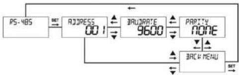
flowchart
graph TD
    A["PS-485"] --> B["ADDRESS 001"]
    B --> C["BRUDRATE 9600"]
    C --> D["PARTY NONE"]
    D --> E["BACK MENU"]
    E --> F["SET"]
    F --> A
"ADDRESS" Address Setting
Address information can be entered between 1 and 247.

"BAUDRATE" Baudrate Settings
Enter one of the 2400 bps, 4800 bps, 9600 bps, 19200 bps, 38400 bps values as stated in the communication software.

flowchart
graph LR
    A["3AU/4ATE 9600"] -->|SET| B["3AU/4ATE 9500"]
    B -->|SET+0.00| C["3AU/4ATE 9600"]
    C -->|SET| D["Selected parameter is displayed"]
"PARITY" Parity Setting
Parity can be entered as none, odd or even.
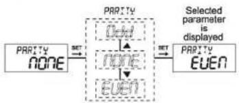
flowchart
graph LR
    A["PARITY\nNONE"] -->|SET| B["PARITY\nNone\nEVEN"]
    B -->|SET| C["Selected parameter is displayed\nPARITY\nEVEN"]
21
MODBUS RTU PROTOCOL
Standart MODBUS RTU message is shown below.
| T | ADDRESS8 BIT | FUNCTION8 BIT | DATA N × 8 BIT | CRCH | CRCL | T |
The T times corresponds to a time in which data must not be exchanged on the communication bus to allow the connected devices to recognize the end of one message and the beginning of another. This time must be at least 3.5 characters at the selected baud rate. Adress range (1-247) is address of the connected device. The data field contains data sent to the slave by master or data sent to master by slave. CRC is a error check method by using MODBUS RTU protocol and consists of 2 bytes.
Modbus Functions:
| 03H | READ HOLD REGISTERS | 10H | PRESET MULTIPLE REGISTERS |
| 06H | PRESET SINGLE REGISTER | 2BH | READ DEVICE INFO |
22
Read Hold (03H) function is used for reading the measured parameter (intantenaous measurement value, minimum and maximum measurement values) and other setting values of the device. If any register other than this area has been tried to read, the device will send an error message. For example; below message can be sent to read the measured voltage value:
| 01DeviceAddress | 03Function | 00MSBAddress | 00LSBAddress | 00RegisternumberMSB | 01RegisternumberLSB | 84CRCMSB | 0A LSB |
Preset Single Register (06H) function is used for change device settings and resetting the measured minimum/maximum values. For example; below message can be sent to set the period value to 100:
| 01DeviceAddress | 06Function | 80MSBAddress | 27LSBAddress | 00DataMSB | 64DataLSB | 11CRCMSB | EA CRCLSB |
Preset Multiple register (10H) function is used for changing more than one register value. For example; below message can be sent to set the contrast value to 10 and the period value to 100:
| 01DeviceAddress | 10Function | 80MSBAddr. | 26LSBAddr. | 00RegisternumberMSB | 02RegisternumberLSB | 04Bytecount | 00DataMSB | 0ADataLSB | 00DataMSB | 64DataLSB | 31CRCMSB | B2CRCLSB |
Read device info (2BH) function is used to learn the manufacturer name, the device code, hardware version and software version. The query packet to read the device info is as following: 01 2B 0E 01 00 70 77
2.2.5 "RESET" Reset Menu
Minimum and maximum values among measured voltage values are stored on the device. Reset menu is used in order to delete these values. There are 2 sub-menus under Reset menu: "RESET MIN", "RESET MAX". To see the measured minimum and maximum values, refer to the "Special Functions for Buttons" section of this user manual.
NOTE: Stored values are not affected from power outages. Measured minimum and maximum values are deleted after you select YES option under the value that you want to reset and approve the changes when you exit or a zero (0) value is written into the addresses that these values are stored.

flowchart
graph TD
    A["RESET"] --> B["RESET MIN"]
    B --> C["RESET MAX"]
    C --> D["BACK MENU"]
    D --> E["SET"]
    E --> A
    style A fill:#f9f,stroke:#333
    style B fill:#ccf,stroke:#333
    style C fill:#cfc,stroke:#333
    style D fill:#fcc,stroke:#333
"RESET MIN" Minimum Value Reset Menu
It is the menu where stored minimum voltage value is deleted.
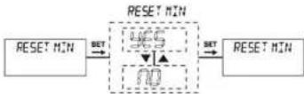
"RESET MAX" Maximum Value Reset Menu
It is the menu where stored maximum voltage value is deleted.
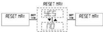
2.2.6 "DISPLAYSET" Display Setting Menu
Settings about the device display are done in this menu. Display setting menu has 2 sub-menus: "BACKLIGHT", "CONTRAST".

flowchart
graph TD
    A["DISPLAYSET"] --> B["BYCALTIGHT"]
    B --> C{YES}
    C --> D["CONTRAST"]
    D --> E["BYC MENU"]
    E --> F{IS}
    F --> G["Feedback to BYC"]
    G --> A
"BACKLIGHT" LCD Backlight Setting Menu
Backlight feature of the device is configured in this menu. Available choices are as following: "NO" Off. "YES" Continuously on. "30 s" On for 30 seconds, "60 s" On for 1 minute, "300 s" On for 5 minutes, "900 s" On for 15 minutes. Backlight turns off after the selected time if no button is pressed at the end of that time.
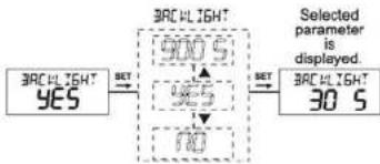
flowchart
graph LR
    A["30C V LIGHT YES"] -->|SET| B["30C V LIGHT"]
    B --> C["900 S"]
    B --> D["100 S"]
    C --> E["Selected parameter is displayed."]
    D --> E
    E --> F["30 S"]
"CONTRAST" Contrast Setting Menu
Contrast of the device display is set in this menu. It can be set to a value between "00" and "15".

2.2.7 "LANGUAGE" Language Setting Menu
Language of the device is set in this menu. There are 5 language options as "Tr" Turkish, "Eng" English, "dE" German, "ESP" Spanish and "FR" French.

flowchart
graph LR
    A["输入"] --> B["SET"]
    B --> C["中间处理模块"]
    C --> D["SET"]
    D --> E["LANGUAGE ENG"]
27
2.2.8 "FCTRY SET" Factory Setting Menu
Factory settings are loaded in this menu. A 4 digit password is asked when entering this menu. If password protection is active, the password isn't asked again when entering this menu because it was entered during entering the main menu. If "YES" option is selected in this menu and "SAVE" confirmation is approved at the exit of main menu, factory settings are loaded (Refer to: Factory Default Values).
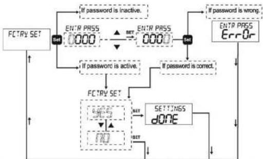
flowchart
graph TD
    A["FCTRY SET"] --> B["Set"]
    B --> C{If password is inactive.}
    C -->|Yes| D["ENTR PRESS 0000"]
    C -->|No| E["SET"]
    D --> F{ENTR PRESS 0000}
    F --> G["Set"]
    G --> H{If password is wrong.}
    H --> I["ERROr"]
    G --> J{If password is correct.}
    J --> K["FCTRY SET"]
    K --> L{SET}
    L -->|Yes| M["END"]
    L -->|No| N["SETTINGS DONE"]
    M --> O["End"]
    N --> O
NOTE: When factory settings are loaded, language setting stays unchanged. The language will be the same as the on selected last.
28
2.2.9 "SECURITY" Security Setting Menu
Device password settings are done in this menu. There are 2 sub-menus under SECURITY menu. "PASS ACTV", "PASS CHNG". Password activation and changing operations are done under these menus. Factory default password is "0000".
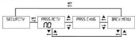
flowchart
graph TD
    A["SECURITY"] -->|SET| B["NO"]
    B --> C["PASS ACTV"]
    C --> D["PASS CHNG"]
    D --> E["BACK MENU"]
    E -->|SET| A
    E -->|NO| F["↓"]
    F --> G["↓"]
    G --> H["↓"]
    H --> I["↓"]
    I --> J["↓"]
    J --> K["↓"]
    K --> L["↓"]
    L --> M["↓"]
    M --> N["↓"]
    N --> O["↓"]
    O --> P["↓"]
    P --> Q["↓"]
    Q --> R["↓"]
    R --> S["↓"]
    S --> T["↓"]
    T --> U["↓"]
    U --> V["↓"]
    V --> W["↓"]
    W --> X["↓"]
    X --> Y["↓"]
    Y --> Z["↓"]
    Z --> A
"PASS ACTV" Password Activation Menu
Password protection is activated or deactivated in this menu.

flowchart
graph LR
    A["PRSS ACTV PS IUE"] --> B["ENTR PASS 0000"]
    B --> C["ENTR PASS 0000"]
    C --> D["Selected parameter is displayed."]
    D --> E["PRSS ACTV ACEUE"]
29
"CHNG PASS" Change Password Menu
Password is changed in this menu.
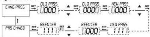
flowchart
graph TD
    A["CHNG PASS"] --> B["QL1 PASS"]
    B --> C["QL2 PASS"]
    C --> D["NEW PASS"]
    E["PRS CHNG3"] --> F["REENTER"]
    F --> G["QL1"]
    G --> H["QL2"]
    H --> I["NEW PASS"]
    J["SET"] --> K["000"]
    L["SET"] --> M["000"]
    N["SET"] --> O["000"]
    P["SET"] --> Q["111"]
    R["SET"] --> S["111"]
2.2.10 "INFO" Menu
This menu display shows software and hardware version as well as serial number of the device. It has 3 sub-menus.. "SOFT VER", "HARD VER", "SERI NO".
"SOFT VER"
This menu display shows the software version of the device.
"HARD VER"
This menu display shows the hardware version of the device.
"SERI NO"
This menu display shows the serial number of the device.

flowchart
graph TD
    A["INFO"] -->|SET| B["SOFT PER 2.00.00"]
    B --> C["HARPER PER 2.00.00"]
    C --> D["SERI NO 0000"]
    D --> E["BACK MENU"]
    E -->|←| F["↓"]
    F --> G["↔"]
    G --> H["↔"]
    H --> I["↔"]
    I --> J["↔"]
    J --> K["↔"]
    K --> L["↔"]
    L --> M["↔"]
    M --> N["↔"]
    N --> O["↔"]
    O --> P["↔"]
    P --> Q["↔"]
    Q --> R["↔"]
    R --> S["↔"]
    S --> T["↔"]
    T --> U["↔"]
    U --> V["↔"]
    V --> W["↔"]
    W --> X["↔"]
    X --> Y["↔"]
    Y --> Z["↔"]
    Z --> A
30
2.2.11 "ESCAPE" Exiting Main Menu
It is used to exit the main menu. If any changes has been made in the menus, a confirmation is asked to save those changes. If there are no changes, measurement results are displayed without a confirmation.

flowchart
graph LR
    A["ESCAPE"] --> B["SET"]
    B --> C["SR/VE"]
    C --> D{no}
    D -->|SET| E["Changes are saved."]
    D -->|SET| F["Changes are discarded."]
    E --> G["MEASUREMENT SCREEN 024.00 V"]
    F --> G
3. INSTALLATION
3.1. DIMENSIONS AND INSTALLATION
Dimensions

Panel Cutout Dimensions

Control Panel Area Dimensions

3.2. CONNECTION DIAGRAM

* Only for DCV-10C/10CS/11C/11CS
** Only for DCV-10A/11A
*** Only for DCV-10S/10CS/11S/11CS
**** Only for DCV-10/10A/10C/10S/10CS
***** Only for DCV-11/11A/11C/11S/11CS
3.3. PC CONNECTION
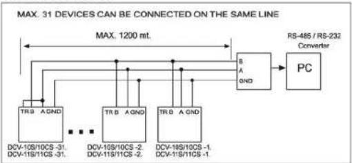
flowchart
graph LR
    A["TR0 A GND"] --> B["Max. 1200 mt."]
    C["TR0 A GND"] --> D["Max. 1200 mt."]
    E["TR0 A GND"] --> F["Max. 1200 mt."]
    G["TR0 A GND"] --> H["Max. 1200 mt."]
    I["BS A GND"] --> J["PC"]
    K["DSV-10S/10CS-31, DCV-11S/11CS-31"] --> A
    L["DSV-10S/10CS-2, DCV-11S/11CS-2"] --> C
    M["DSV-19S/10CS-1, DCV-11S/11CS-1"] --> E
    N["DSV-19S/10CS-1"] --> F
    O["DSV-19S/10CS-1"] --> H
    P["DSV-19S/10CS-1"] --> I
    Q["DSV-19S/10CS-1"] --> L
    R["DSV-19S/10CS-1"] --> M
    S["DSV-19S/10CS-1"] --> N
    T["DSV-19S/10CS-1"] --> O
    U["DSV-19S/10CS-1"] --> P
    V["DSV-19S/10CS-1"] --> M
    W["DSV-19S/10CS-1"] --> N
    X["DSV-19S/10CS-1"] --> O
    Y["DSV-19S/10CS-1"] --> P
    Z["DSV-19S/10CS-1"] --> M
    AA["DSV-19S/10CS-1"] --> N
    AB["DSV-19S/10CS-1"] --> O
    AC["DSV-19S/10CS-1"] --> P
    AD["DSV-19S/10CS-1"] --> N
    AE["DSV-19S/10CS-1"] --> O
    AF["DSV-19S/10CS-1"] --> P
    AG["DSV-19S/10CS-1"] --> N
    AH["DSV-19S/10CS-1"] --> O
    AI["DSV-19S/10CS-1"] --> P
    AJ["DSV-19S/10CS-1"] --> N
    AK["DSV-19S/10CS-1"] --> O
    AL["DSV-19S/10CS-1"] --> P
    AM["DSV-19S/10CS-1"] --> N
    AN["DSV-19S/10CS-1"] --> O
    AO["DSV-19S/10CS-1"] --> P
    AP["DSV-19S/10CS-1"] --> N
    AQ["DSV-19S/10CS-1"] --> O
    AR["DSV-19S/10CS-1"] --> P
    AS["DSV-19S/10CS-1"] --> N
    AT["DSV-19S/10CS-1"] --> O
    AU["DSV-19S/10CS-1"] --> P
    AV["DSV-19S/10CS-1"] --> N
    AW["DSV-19S/10CS-1"] --> O
    AX["DSV-19S/10CS-1"] --> P
    AY["DSV-19S/10CS-3"]
    AZ["DSV-19S/10CS-3"]
    BA["DSV-19S/10CS-3"]
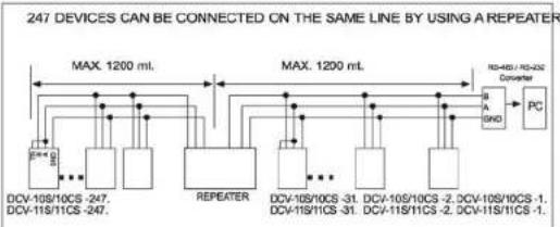
flowchart
graph LR
    A["DCV-10S/10CS -247. DCV-11S/11CS -247."] --> B["REPEATER"]
    B --> C["DCV-10S/10CS -31. DCV-11S/10CS -31. DCV-10S/10CS -2. DCV-10S/10CS -1. DCV-11S/11CS -2. DCV-11S/11CS -1."]
    C --> D["PC"]
    E["Max 1200 mL"] --> F["Max 1200 mL"]
    G["DCV-10S/10CS -247. DCV-11S/11CS -247."] --> H["DCV-10S/10CS -31. DCV-10S/10CS -2. DCV-10S/10CS -1. DCV-11S/11CS -2. DCV-11S/11CS -1."]
4. FACTORY DEFAULT VALUES:
Alarms:(DCV-10C/10CS/11C/11CS)
- Alarm:
Alarm Status
Latch
Trip
Contact Position (Output Inverse)
Alarm Type
High Alarm Value
Low Alarm Value
High Alarm Hysteresis
Low Alarm Hysteresis
High Alarm On Delay (d_on_time)
High Alarm Off Delay (d_off_time)
Low Alarm On Delay (d_on_time)
Low Alarm Off Delay (d_off_time)
2.Alarm:
Alarm Status
Latch
Trip
Contact Position (Output Inverse)
Alarm Type
High Alarm Value
Low Alarm Value
High Alarm Hysteresis
: Passive
: Off
: Off
: Off
: High Alarm
: 100V
: 10V
: 10
: 5
: 20s
: 10s
: 20s
: 10s
广力云智慧零售收银系统
: Passive
: Off
: Off
: Off
: High Alarm
: 100V
: 10V
: 10
| Low Alarm Hysteresis | : 5 |
| High Alarm On Delay (d_on_time) | : 20s |
| High Alarm Off Delay (d_off_time) | : 10s |
| Low Alarm On Delay (d_on_time) | : 20s |
| Low Alarm Off Delay (d_off_time) | : 10s |
| RS 485: (DCV-10S/10CS/11S/11CS) | |
| Address | : 1 |
| Baudrate | : 9600 |
| Parity | : None |
| Analog Output: (DCV-10A/11A) | |
| Analog Output | : 0 - 20 mA |
| Assign Hi | : 200V |
| Assign Lo | : 0V |
| Period | : 1 (second) |
| Display | |
| Backlight | : On |
| Contrast | : 15 |
| Security | |
| Password Protection | : Off |
| Password | : 0 |
5. TECHNICAL FEATURES:
Operating Voltage (Un)
Frequency
Supply Input Power Consumption
Measuring Input Power Consumption
Measuring Input Resistance (Rin)
Measuring Voltage Range
Accuracy
Relay Outputs (2 pieces)
Communication
Baudrate
Address
Parity
Analog Output
Analog Voltage Output
Load Resistance
Update Period
Analog Current Output
Load Resistance
Update Period
Accuracy
Period
:85-265V AC/DC (DCV-10/10A/10C/10S/10CS).
10-56V DC (DCV-11/11A/11C/11S/11CS)
:50/60 Hz (DCV-10/10A/10C/10S/10CS)
:<4 VA
:<1 VA
:<2M
:+/- 200V
:0.5% ±1 Digit [(10% - 100%) x full scale] **
:2 NO, 5A 1250 VA (DCV-10C/10CS/11C/11CS)
:MODEUS RTU (RS-485) Programmable.(DCV-10S/10CS/11S/11CS)
:2400-38400
:1-247
:None, Odd, Even
:(DCV-10A/11A)
:0-10 V or 2-10 V
:>=1K2 Ohm
:100ms (milliseconds).
:0-20 mA or 4-20 mA
:<= 500ohm
:100ms (milliseconds).
+0.01% ES
:1 - 600 seconds
Ambient Temperature : -20 ... 70°C
Display :2.5 inches Backlit LCD
Dimensions :PR-20
Device Protection Class :Double Insulation - Class II (☐)
Casing Protection Class :IP 40
Terminal Protection Class :IP 00
Wire Width (For Terminals) :2.5mm2
Casing Material : Nonflammable
Installation Type :Flush Mounting ( PR-20 )
Weight :0.240 kg
Installation Class :Class III
Panel Cutout Dimensions :48X96 mm (PR-20)
** Measurement accuracy may change when measured waveform is not pure DC. (Measuring error may increase to 5% for half-wave and full-wave rectified AC signals. Capacitive filter usage is suggested to increase the precision for measuring such signals.) It is recommended to use "Capactive filter" in order to improve accuracy of measurements.
- REGISTER TABLE:
| Bit Register Table | ||||||
| Address (HEX) | Description | WR | Range | Unit | Multiplier | Format |
| 0x0000 | DC Voltage Value | R | +/- 20000 | V | 0,01 | signed int |
| 0x0001 | Max. Measurement Value | R/W | +/- 20000 | V | 0,01 | signed int |
| 0x0002 | Min. Measurement Value | R/W | +/- 20000 | V | 0,01 | signed int |
| 0x8000 | Shunt Current * | R/W | 1 – 10000 | A | 1 | unsigned int |
| 0x8001 | Shunt Voltage * | R/W | 50-150 | mV | 1 | unsigned int |
| 0x8002 | Alarm 1 Activation | R/W | 0 – 1 | - | 1 | unsigned int |
| 0 → Alarm 1 inactive | ||||||
| 1 → Alarm 1 active | ||||||
| 0x8003 | Alarm 1 Latch Function | R/W | 0-1 | - | 1 | unsigned int |
| 0 → Latch Inactive | ||||||
| 1 → Latch Active | ||||||
| 0x8004 | Alarm 1 Trip Function | R/W | 0-1 | - | 1 | unsigned int |
| 0 → Trip Inactive | ||||||
| 1 → Trip Active | ||||||
* Only valid for DCA-10/10A/10C/10S/10CS/11/11A/11C/11S/11CS.
| Address (HEX) | Description | WR | Range | Unit | Multiplier | Format |
| 0x8005 | Alarm 1 Contact Position | R/W | 0-1 | - | 1 | unsigned int |
| 0 ----> Normal | ||||||
| 1 ----> Inverted | ||||||
| 0x8006 | Alarm 1 Alarm Type | R/W | 0-2 | - | 1 | unsigned int |
| 0 ----> High Protection Active | ||||||
| 1 ----> Low Protection Active | ||||||
| 2 ----> Range Protection Active | ||||||
| 0x8007 | Alarm 1 High Warning Value | R/W | +/- 20000 | v | 0,1 | long int |
| 0x8009 | Alarm 1 Low Warning Value | R/W | +/- 20000 | v | 0,1 | long int |
| 0x800B | Alarm 1 High Hysteresis | R/W | 0-20 | % | 1 | unsigned int |
| 0x800C | Alarm 1 Low Hysteresis | R/W | 0-20 | % | 1 | unsgined int |
| 0X800D | Alarm 1 High Alarm ON Delay | R/W | 0-9999 | second | 0,1 | unsigned int |
| 0x800E | Alarm 1 High Alarm OFF Delay | R/W | 0-9999 | second | 0,1 | unsigned int |
| Address (HEX) | Description | WR | Range | Unit | Multiplier | Format |
| 0x800F | Alarm 1Low AlarmON Delay | R/W | 0-9999 | saniye | 0,1 | unsigned int |
| 0x8010 | Alarm 1Low AlarmOFF Delay | R/W | 0-9999 | saniye | 0,1 | unsigned int |
| 0x8011 | Alarm 2Activation | R/W | 0-1 | - | 1 | unsigned int |
| 0 --> Protection Inactive | ||||||
| 1 --> Protection Active | ||||||
| 0x8012 | Alarm 2Latch Function | R/W | 0-1 | - | 1 | unsigned int |
| 0 --> Latch Inactive | ||||||
| 1 --> Latch Active | ||||||
| 0x3013 | Alarm 2Trip Function | R/W | 0-1 | - | 1 | unsigned int |
| 0 --> Trip Inactive | ||||||
| 1 --> Trip Active | ||||||
| 0x3014 | Alarm 2Contact Position | R/W | 0-1 | - | 1 | unsigned int |
| 0 --> Normal | ||||||
| 1 --> Inverted | ||||||
| 0x3015 | Alarm 2Alarm Type | R/W | 0-2 | - | 1 | unsigned int |
| 0 --> High Protection Active | ||||||
| 1 --> Low Protection Active | ||||||
| 2 --> Range Protection Active | ||||||
| Addres (HEX) | Description | W/R | Range | Unit | Multiplier | Format |
| 0x8016 | Alarm 2High Warning Value | R/W | +/- (Shunt Current) | v | 1 | long int |
| 0x8018 | Alarm 2Low Warning Value | R/W | +/- (Shunt Current) | v | 1 | long int |
| 0x8001A | Alarm 2High Hysteresis | R/W | 0-20 | % | 1 | ungined int |
| 0x8001B | Alarm 2Low Hysteresis | R/W | 0-20 | % | 1 | ungined int |
| 0x8001C | Alarm 2High AlarmON Delay | R/W | 0-9999 | second | 0,1 | unsigned int |
| 0x8001D | Alarm 2High AlarmOFF Delay | R/W | 0-9999 | second | 0,1 | unsigned int |
| 0x8001E | Alarm 2Low AlarmON Delay | R/W | 0-9999 | second | 0,1 | unsigned int |
| 0x8001F | Alarm 2Low AlarmOFF Delay | R/W | 0-9999 | second | 0,1 | unsigned int |
| Address (HEX) | Description | W / R | Alarm Status | Unit | Multiplier | Format |
| 0x8020 | Alarm1 Status | R | 0: Alarm doesn't count1: High Alarm2: Low Alarm | - | 1 | unsigned int |
| 0x8021 | Alarm2 Status | R | 0: Alarm doesn't count1: High Alarm2: Low Alarm | - | 1 | unsigned int |
| Address (HEX) | Description | W/R | Range | Unit | Multiplier | Format |
| 0x8022 | Analog Output Type/Range | R/W | 0-4 | - | 1 | unsigned int |
| 0 OUTPUT INACTIVE | ||||||
| 1 OUTPUT TYPE VOLT RANGE = 0-10 V | ||||||
| 2 OUTPUT TYPE VOLT RANGE = 2-10 V | ||||||
| 3 OUTPUT TYPE CURRENT RANGE = 0-20 mA | ||||||
| 4 OUTPUT TYPE CURRENT RANGE = 4-20 mA | ||||||
| 0x8023 | Assign Hi | R/W | +/- 20000 | v | 0,1 | long int |
| 0x8025 | Assign Lo | R/W | +/- 20000 | v | 0,1 | long int |
| 0x8027 | Comm. Address | R/W | 1-247 | - | 1 | unsigned int |
| 0x8026 | Baud Rate | R/W | 0--4 | bps | 1 | unsigned int |
| 0--2400 | ||||||
| 1--4800 | ||||||
| 2--9600 | ||||||
| 3--19200 | ||||||
| 4--38400 | ||||||
| 0x8029 | Parity | R/W | 0-2 | - | 1 | unsigned int |
| 0-->None,1-->Ost,2-->Even | ||||||
| 0x802A | Pass. Protection | R/W | 0-->Off -1-->On | - | 1 | unsigned int |
| 0x802B | Password | R/W | 0-9999 | - | 1 | unsigned int |
| Address (HEX) | Description | W/R | Range | Unit | Multiplier | Format |
| 0x802C | Backlight Status | R/W | 0~4 | - | 1 | unsigned int |
| 0→Backlight Off | ||||||
| 1→Backlight On continuously | ||||||
| 2→Backlight On for 30 seconds | ||||||
| 3→Backlight On for 1 minute | ||||||
| 4→Backlight On for 5 minutes | ||||||
| 5→Backlight On for 15 minutes | ||||||
| 0x802D | Contrast | R/W | 0-15 | |||
| 0x802E | Average Period | R/W | 1~600 | second | 1 | unsigned int |
| 0x802F | Language | R/W | 0~4 | - | 1 | unsigned int |
| 0:TR 1:ENG 2:DE 3:FR 4:ESP |
| 32 Bit Register Table | ||||||
| Address (HEX) | Description | WR | Range | Unit | Multiplier | Format |
| 0x4J00 | DC Current Value | R | +/- 10000000 | A | 0,001 | long int |
| 0x4J02 | Max. Measurement Value | R/W | +/- 10000000 | A | 0,001 | long int |
| 0x4J04 | Min. Measurement Value | R/W | +/- 10000000 | A | 0,001 | long int |
Note: When these addresses are read on a DCV Series device, 0 (zero) value will be read.
| EC00 | DEVICE ID | R | 0xB601-0xB604 | - | 1 | unsigned int |
| EC01 | DEVICE ID && VERSION NO | R | 0x0111 - 0x01FF | - | 1 | unsigned int |
| EC02 | SERIAL NO | R | 0x0000 - 0xFFFF | - | 1 | unsigned int |
| EC03 | - | 1 | unsigned int | |||
| EC04 | SOFTWARE VERSION | R | - | 1 | unsignedlong | |
| EC06 | HARDWARE VERSION | R | - | 1 | unsignedlong | |
| EC08 | MODBUS TABLE VERSION | R | - | 1 | unsignedlong | |
| EC0A | PRODUCTION DATE | R | - | 1 | unix time | |
| EC0C | CALIBRATION DATE | R | - | 1 | unix time |
| DEVICE ID | DEVICE TYPE | DEVICE ID | DEVICE TYPE | DEVICE ID | DEVICE TYPE | DEVICE ID | DEVICE TYPE |
| B60101 | DCA-1C | B60201 | DCV-10 | B60301 | DCA-11 | B60401 | DCV-11 |
| B60102 | DCA-10A | B60202 | DCV-10A | B60302 | DCA-11A | B60402 | DCV-11A |
| B60103 | DCA-10S | B60203 | DCV-10S | B60303 | DCA-11S | B60403 | DCV-11S |
| B60104 | DCA-10C | B60204 | DCV-10C | B60304 | DCA-11C | B60404 | DCV-11C |
| B60105 | DCA-10CS | B60205 | DCV-10CS | B60305 | DCA-11CS | B60405 | DCV-11CS |
| Supported Modbus Functions: | |
| 03H | READ HOLD REGISTERS |
| 06H | PRESET SINGLE REGISTER |
| 10H | PRESET MULTIPLE REGISTERS |
| 2BH | READ DEVICE INFO |
| Data Type | Size |
| signed int | 16 bit |
| unsigned int | 16 bit |
| long int | 32 bit |
| unsigned long | 32 bit |
When a reading operation from addresses that are not present on the device is done, 0 (zero) value will be read. When a writing operation to addresses that are not present on the device is done, no writing is done and no error code is returned.
- MENU MAP
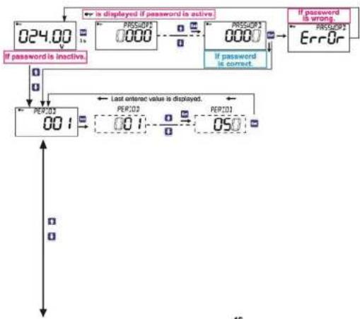
flowchart
graph TD
    A["024.00"] --> B{is displayed if password is active}
    B --> C["0000"]
    C --> D{0000?}
    D --> E["0000"]
    E --> F{errOr}
    F --> G["001"]
    G --> H{PERIOD 001?}
    H --> I["050"]
    I --> J{PERIOD 050?}
    J --> K["Last entered value is displayed."]
    K --> L["001"]
    L --> M{If password is inactive}
    M --> N["0000"]
    N --> O{If password is correct}
    O --> P["0000"]
    P --> Q["ERROr"]
    Q --> R["001"]
    R --> S["PERIOD 050"]
    S --> T["001"]
    T --> U["PERIOD 050"]

flowchart
graph TD
    A["RLRMS"] --> B["RLRMS 1"]
    A --> C["RLRMS 2"]
    A --> D["BRC+NEW"]
    B --> E["OFF"]
    C --> F["OFF"]
    D --> G["H 19H"]
    E --> H["Selected parameter is displayed."]
    F --> I["Selected parameter is displayed."]
    G --> J["High Value 100"]
    G --> K["Low Value 0.10"]
    G --> L["High Value 100"]
    G --> M["Low Value 0.10"]
    G --> N["High Value 0.20.0"]
    G --> O["Low Value 0.10"]
    H --> P["354 KOS 05"]
    I --> Q["3 BICHE 5 020.0"]
    J --> R["3 JONHE 5 0.10.0"]
    K --> S["BRC MENU 020.0"]
    L --> T["BRC MENU 0.10.0"]
    M --> U["BRC MENU 0.10.0"]
    N --> V["BRC MENU 0.10.0"]
    O --> W["BRC MENU 0.10.0"]
    P --> X["LATCH 70"]
    Q --> Y["LATCH 70"]
    R --> Z["LATCH 70"]
    S --> AA["LATCH 70"]
    T --> AB["LATCH 70"]
    U --> AC["LATCH 70"]
    V --> AD["LATCH 70"]
    W --> AE["LATCH 70"]
    X --> AF["LATCH 70"]
    Y --> AG["LATCH 70"]
    Z --> AH["LATCH 70"]
    AA --> AI["LATCH 70"]
    AB --> AJ["LATCH 70"]
    AC --> AK["LATCH 70"]
    AD --> AL["LATCH 70"]
    AE --> AM["LATCH 70"]
    AF --> AN["LATCH 70"]
    AG --> AO["LATCH 70"]
    AH --> AP["LATCH 70"]
    AI --> AQ["LATCH 70"]
    AJ --> AR["LATCH 70"]
    AK --> AS["LATCH 70"]
    AL --> AT["LATCH 70"]
    AM --> AU["LATCH 70"]
    AN --> AV["LATCH 70"]
    AO --> AW["LATCH 70"]
    AP --> AX["LATCH 70"]
    AQ --> AY["LATCH 70"]
    AR --> AZ["LATCH 70"]
    AS --> BA["LATCH 70"]
    AT --> BB["LATCH 70"]
    AU --> BC["LATCH 70"]
    AV --> BD["LATCH 70"]
    AW --> BE["LATCH 70"]
    AX --> BF["LATCH 70"]
    AY --> BG["LATCH 70"]
    AZ --> BH["LATCH 70"]

flowchart
graph TD
    A["Input"] --> B["0-20 mA"]
    B --> C["RALE OUT 0-20 mA"]
    C --> D["RALE OUT 4-20 mA"]
    D --> E["RALE OUT 8-10 v"]
    E --> F["RALE OUT 2-10 v"]
    F --> G["HIGHEST 100 v"]
    G --> H["Last entered value is displayed."]
    H --> I["HIGHEST 200 v"]
    I --> J["LIGHEST 000 v"]
    J --> K["BRICH MENU"]
    K --> L["Output"]
    style A fill:#f9f,stroke:#333
    style B fill:#ccf,stroke:#333
    style C fill:#cfc,stroke:#333
    style D fill:#fcc,stroke:#333
    style E fill:#cff,stroke:#333
    style F fill:#ffc,stroke:#333
    style G fill:#fcf,stroke:#333
    style H fill:#cff,stroke:#333
    style I fill:#fcf,stroke:#333
    style J fill:#cff,stroke:#333
    style K fill:#ffc,stroke:#333
    style L fill:#cfc,stroke:#333
49

flowchart
graph TD
    A["PS485"] --> B["ADDRESS 001"]
    B --> C["RJDRATE 9600"]
    C --> D["PROPTY none"]
    D --> E["BRL & MENU"]
    E --> F["Only valid for DCV-90S/10CS/11S/11CS."]
    B --> G["RJDRATE 001"]
    G --> H["Last second permutation is displayed."]
    C --> I["RJDRATE 9600"]
    I --> J["Last second permutation is displayed."]
    D --> K["PROPTY none"]
    K --> L["Last second permutation is displayed."]
    E --> M["BRL & MENU"]
    M --> N["Last second permutation is displayed."]
50

flowchart
graph TD
    A["RESET"] --> B["RESET HIN"]
    B --> C["RESET HFE"]
    C --> D["BPL+HOU"]
    D --> E["AND"]
    E --> F["RESET HIN"]
    F --> G["RESET HFE"]
    G --> H["BPL+HOU"]
    H --> I["AND"]
    I --> J["RESET HIN"]
    J --> K["RESET HFE"]
    K --> L["BPL+HOU"]
    L --> M["AND"]
    M --> N["RESET HIN"]
    N --> O["RESET HFE"]
    O --> P["BPL+HOU"]
    P --> Q["AND"]
    Q --> R["RESET HIN"]
    R --> S["RESET HFE"]
    S --> T["BPL+HOU"]
    T --> U["AND"]
    U --> V["RESET HIN"]
    V --> W["RESET HFE"]
    W --> X["BPL+HOU"]
    X --> Y["AND"]
    Y --> Z["RESET HIN"]
    Z --> AA["RESET HFE"]
    AA --> AB["BPL+HOU"]
    AB --> AC["AND"]
    AC --> AD["RESET HIN"]
    AD --> AE["RESET HFE"]
    AE --> AF["BPL+HOU"]
    AF --> AG["AND"]
    AG --> AH["RESET HIN"]
    AH --> AI["RESET HFE"]
    AI --> AJ["BPL+HOU"]
    AJ --> AK["AND"]
    AK --> AL["RESET HIN"]
    AL --> AM["RESET HFE"]
    AM --> AN["BPL+HOU"]
    AN --> AO["AND"]
    AO --> AP["RESET HIN"]
    AP --> AQ["RESET HFE"]
    AQ --> AR["BPL+HOU"]
    AR --> AS["AND"]
    AS --> AT["RESET HIN"]
    AT --> AU["RESET HFE"]
    AU --> AV["BPL+HOU"]
    AV --> AW["AND"]
    AW --> AX["RESET HIN"]
    AX --> AY["RESET HFE"]
    AY --> AZ["BPL+HOU"]
    AZ --> BA["AND"]
    BA --> BB["RESET HIN"]
    BB --> BC["RESET HFE"]
    BC --> BD["BPL+HOU"]
    BD --> BE["AND"]
    BE --> BF["RESET HIN"]
    BF --> BG["RESET HFE"]
    BG --> BH["BPL+HOU"]
    BH --> BI["AND"]
    BI --> BJ["RESET HIN"]
    BJ --> BK["RESET HFE"]
    BK --> BL["BPL+HOU"]
    BL --> BM["AND"]
    BM --> BN["RESET HIN"]
    BN --> BO["RESET HFE"]
    BO --> BP["BPL+HOU"]
    BP --> BQ["AND"]
    BQ --> BR["RESET HIN"]
    BR --> BS["RESET HFE"]
    BS --> BT["BPL+HOU"]
    BT --> BU["AND"]
    BU --> BV["RESET HIN"]
    BV --> BW["RESET HFE"]
    BW --> BX["BPL+HOU"]
    BX --> BY["AND"]
    BY --> BZ["RESET HIN"]
    BZ --> CA["RESET HFE"]
    CA --> CB["BPL+HOU"]

flowchart
graph TD
    A["LYNGURSE"] --> B["If password is inactive"]
    B --> C{000?}
    C -->|Yes| D["ETUP PRESS"]
    C -->|No| E{000?}
    E -->|Yes| F["ETUP PRESS"]
    E -->|No| G["If password is active"]
    G --> H{00?}
    H -->|Yes| I["SET: N65"]
    H -->|No| J["done"]
    I --> K["SET: N65"]
    J --> L["End"]
    style A fill:#f9f,stroke:#333
    style K fill:#ccf,stroke:#333
    style L fill:#ccf,stroke:#333
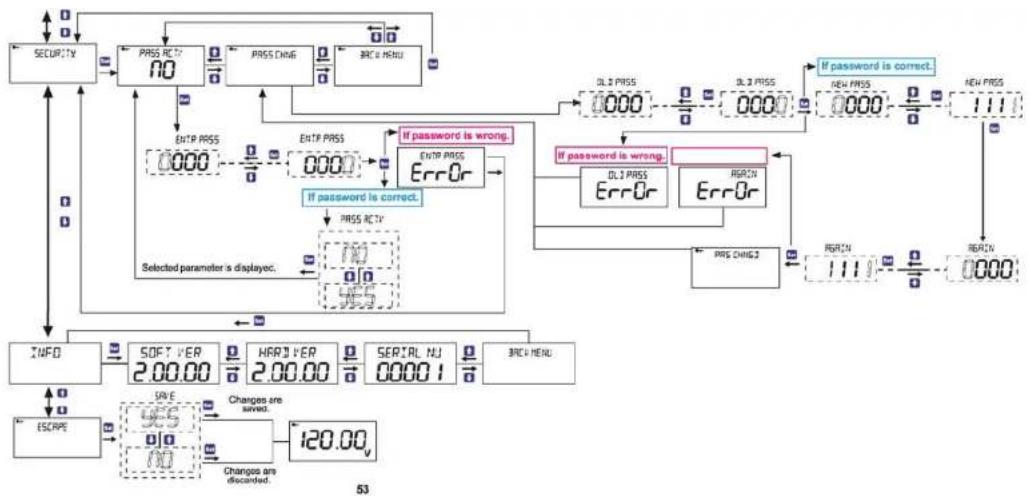
flowchart
graph TD
    A["SECURITY"] --> B["PRSS RECY NO"]
    B --> C["PRSS CHNG"]
    C --> D["BRE MENU"]
    D --> E["INIT PRSS 0000"]
    E --> F["ENTP PRSS 0000"]
    F --> G["ERROr"]
    G --> H{If password is wrong.}
    H -->|Yes| I["OK"]
    H -->|No| J["Error"]
    I --> K["PRSS RECY"]
    J --> L["Selected parameter is displayoc."]
    K --> M["INFO"]
    L --> N["SOFT VER 2.00.00"]
    N --> O["HARDYER 2.00.00"]
    O --> P["SERIAL NJ 00001"]
    P --> Q["BRE MENU"]
    Q --> R["ESCRIPT"]
    R --> S["SAVE"]
    S --> T{Changes are saved.}
    T -->|Yes| U["OK"]
    T -->|No| V["Change to discarded"]
    V --> W["120.00v"]
    W --> X["53"]
    X --> Y["If password is correct."]
    Y --> Z["OLI PRSS 0000"]
    Z --> AA["OLI PRSS 0000"]
    AA --> AB["ORRIN"]
    AB --> AC["ORRIN"]
    AC --> AD["ORRIN"]
    AD --> AE["1111"]
    AE --> AF["ORRIN"]
- SECURITY
- Warnings
- Guarantee
- Index
- INTRODUCTION
- APPLICATIONS:
- GENERAL FEATURES
- FRONT PANEL
- Usage of Front Panel and Buttons
- Special Functions for Buttons
- HARDWARE FEATURES
- 2- USAGE OF DEVICE:
- MENU USAGE AND SETTINGS:
- MAIN MENUS:
- "PERIOD" Period Setting Menu
- "ALARMS" Alarms Menu
- "ALARM1"Alarm 1 Setting Menu
- "ALRM STAT" Alarm Status Setting Menu
- "CONTACT POS" Contact Position Setting Menu
- "TRIP"
- "LATCH"
- "ALRM TYPE" Alarm Type Setting Menu
- HIGH ALARM
- "HGH VALUE"
- "HIGH HYS"
- "H ON DEL"
- "H OFF DEL"
- LOW ALARM
- "LOW VALUE"
- "LOW HYS"
- "L ON DEL"
- "LOFF DEL"
- "ANLG OUT" Analog Output Setting Menu
- "ANLG OUT"
- "HIGHEST"
- "LOWEST"
- "RS-485" Serial Communication Setting Menu
- "ADDRESS" Address Setting
- "RESET" Reset Menu
- "RESET MIN" Minimum Value Reset Menu
- "RESET MAX" Maximum Value Reset Menu
- "DISPLAYSET" Display Setting Menu
- "BACKLIGHT" LCD Backlight Setting Menu
- "CONTRAST" Contrast Setting Menu
- "LANGUAGE" Language Setting Menu
- "FCTRY SET" Factory Setting Menu
- "SECURITY" Security Setting Menu
- "PASS ACTV" Password Activation Menu
- "CHNG PASS" Change Password Menu
- "INFO" Menu
- "SOFT VER"
- "HARD VER"
- "SERI NO"
- "ESCAPE" Exiting Main Menu
- INSTALLATION
- DIMENSIONS AND INSTALLATION
- FACTORY DEFAULT VALUES:
- Alarms:(DCV-10C/10CS/11C/11CS)
- TECHNICAL FEATURES:
- Operating Voltage (Un)
- Frequency
- Supply Input Power Consumption
- Measuring Input Power Consumption
- Measuring Input Resistance (Rin)
- Measuring Voltage Range
- Accuracy
- Relay Outputs (2 pieces)
- Communication
- Analog Output
- Analog Voltage Output
- Period
Brand : ENTES
Model : DCV-11C
Category : Voltmeter