
172 - Professional audio equipment DBX - Free user manual and instructions
Find the device manual for free 172 DBX in PDF.


| Product Type | SuperGate (Gate/Expander/Ducker) |
| Dimensions (H x W x D) | 1.75 x 19 x 9.5 in (4.45 x 48.5 x 24.5 cm) |
| Weight (Net) | 8.25 lb (3.8 kg) |
| Weight (Shipping) | 11 lb (5 kg) |
| Power Requirements | 100–125 VAC or 200–240 VAC, 50/60 Hz, 40 W |
| Rack Space | 1U, full width |
| Operating Temperature | 0 °C to 45 °C (32 °F to 113 °F) |
| Audio Input (XLR) | Balanced, +24 dBu max, 22 kΩ (balanced) / 18.5 kΩ (unbalanced) |
| Audio Output (XLR) | Balanced, +24 dBu into 600 Ω, 30 Ω source impedance |
| Key Input (1/4" TRS) | Balanced, +24 dBu max, 22 kΩ (balanced) / 18.5 kΩ (unbalanced) |
| Frequency Response | 20 Hz – 20 kHz, ±0.5 dB |
| THD | <0.02% at 1 kHz, unity gain; <0.1% 20 Hz – 20 kHz |
| Dynamic Range | 114 dB |
| Threshold Range | -60 dBu to +20 dBu |
| Attenuation (Depth) | 0 dB to 90 dB |
| Attack Time (Minimum) | <5 μs |
| Release Time | 10 ms to 10 s (to 30 dB attenuation) |
| Hold Time | 0 to 3 s |
| Key Filter Slope | 24 dB/octave (4th order bandpass) |
| TCM (Transient Capture Mode) | 300 μs audio path delay |
| Modes | Gate (∞:1), Expand (1:1 to 5:1), Duck |
| Special Features | OneShot, key monitor, stereo coupling (Master), hardwire bypass |
| Input/Output Connectors | XLR (audio in/out), 1/4" TRS (key input) |
| Warranty | 2 years (limited, parts and labor) |
| Safety Compliance | Designed to meet international safety standards; follow all instructions |
Frequently Asked Questions - 172 DBX
User questions about 172 DBX
0 question about this device. Answer the ones you know or ask your own.
Ask a new question about this device
Download the instructions for your Professional audio equipment in PDF format for free! Find your manual 172 - DBX and take your electronic device back in hand. On this page are published all the documents necessary for the use of your device. 172 by DBX.
USER MANUAL 172 DBX
WARNING: TO REDUCE THE RISK OF FIRE OR ELECTRICAL SHOCK, DO NOT EXPOSE THIS APPLIANCE TO RAIN OR MOISTURE.
This symbol, wherever it appears, alerts you to the presence of uninsulated dangerous voltage inside the enclosure — voltage that may be sufficient to constitute a risk of shock.

This symbol, wherever it appears, alerts you to important operating and maintenance instructions in the accompanying literature. Read the manual.
Manufactured under one or more of the following U.S. patents: 3,377,792; 3,681,618; 3,714,462; 3,789,143; 4,097,767; 4,329,598; 4,403,199; 4,409,500; 4,425,551; 4,473,795. Other patents pending.
SuperGate, TCM and OneShot are trademarks of AKG Acoustics, Inc.
This manual is part number 96007-000-03C
© Copyright 1994 by AKG Acoustics, Inc.
400 - FB - 5/94

dbx Professional Products
1525 Alvarado Street, San Leandro, CA 94577 USA
Telephone (1) 510/351-3500 Fax: (1) 510/351-1001
IMPORTANT SAFETY INSTRUCTIONS
All the safety and operating instructions should be read before the appliance is operated.
Retain Instructions: The safety and operation instructions should be retained for future reference.
Heed Warnings: All warnings on the appliance and in the operating instructions should be adhered to.
Follow Instructions: All operation and user instructions should be followed.
Water and Moisture: The appliance should not be used near water (e.g., near a bathtub, washbowl, kitchen sink, laundry tub, in a wet basement, or near a swimming pool, etc.).
Ventilation: The appliance should be situated so that its location or position does not interfere with its proper ventilation. For example, the appliance should not be situated on a bed, sofa, rug, or similar surface that may block the ventilation openings; or, placed in a built-in installation, such as a bookcase or cabinet that may impede the flow of air through the ventilation openings.
Heat: The appliance should be situated away from heat sources such as radiators, heat registers, stoves, or other appliances (including amplifiers) that produce heat.
Power Sources: The appliance should be connected to a power supply only of the type described in the operating instructions or as marked on the appliance.
Grounding or Polarization: Precautions should be taken so that the grounding or polarization means of an appliance is not defeated.
Power-Cord Protection: Power-supply cords should be routed so that they are not likely to be walked on or pinched by items placed upon or against them, paying particular attention to cords at plugs, convenience receptacles, and the point where they exit from the appliance.
Cleaning: The appliance should be cleaned only as recommended by the manufacturer.
Non-use Periods: The power cord of the appliance should be unplugged from the outlet when left unused for a long period of time.
Object and Liquid Entry: Care should be taken so that objects do not fall and liquids are not spilled into the enclosure through openings.
Damage Requiring Service: The appliance should be serviced by qualified service personnel when:
The power supply cord or the plug has been damaged; or
Objects have fallen, or liquid has been spilled into the appliance; or
The appliance has been exposed to rain; or
The appliance does not appear to operate normally or exhibits a marked change in performance; or
The appliance has been dropped, or the enclosure damaged.
Servicing: The user should not attempt to service the appliance beyond that described in the operating instructions. All other servicing should be referred to qualified service personnel.
The Appliance should be used only with a cart or stand that is recommended by the manufacturer.
Safety Instructions (European)
Notice For U.K. Customers If Your Unit Is Equipped With A Power Cord.
WARNING: THIS APPLIANCE MUST BE EARTHED.
The cores in the mains lead are coloured in accordance with the following code:
GREEN and YELLOW - Earth
BLUE - Neutral
BROWN - Live
As colours of the cores in the mains lead of this appliance may not correspond with the coloured markings identifying the terminals in your plug, proceed as follows:
The core which is coloured green and yellow must be connected to the terminal in the plug marked with the letter E, or with the earth symbol, ( 12 ), or coloured green, or green and yellow.
The core which is coloured blue must be connected to the terminal marked N or coloured black.
The core which is coloured brown must be connected to the terminal marked L or coloured red.

The power cord is terminated in a CEE7/7 plug (Continental Europe). The green/yellow wire is connected directly to the unit's chassis. If you need to change the plug and if you are qualified to do so, refer to the table below.
WARNING: If the ground is defeated, certain fault conditions in the unit or in the system to which it is connected can result in full line voltage between chassis and earth ground. Severe injury or death can then result if the chassis and earth ground are touched simultaneously.
| CONDUCTOR | WIRE COLOR | ||
| Normal | Alt | ||
| L | LIVE | BROWN | BLACK |
| N | NEUTRAL | BLUE | WHITE |
| E | EARTH GND | GREEN-YELLOW | GREEN |
AC Power Cord Color Coding
Safety Instructions (German)
Safety Instructions (French)
Safety Instructions (Spanish)
Safety Instructions (Italian)
13 Multi-Channel Connections
13 Key Input Connections
13 . . . . . . . . . . . . . . . . . . . . INSTALLATION CONSIDERATIONS
13 Input/Output Cable Configurations
15 Grounding
16 . . . . . . . . . . . TECHNICAL SUPPORT, FACTORY SERVICE
16 Technical Support, Factory Service
16 Registration Card and User Feedback
16 SCHEMATICS
17 SPECIFICATIONS
21 WARRANTY
21 United States Warranty
21 International Warranty
QUICK SETUP
To get your unit up and running as quickly as possible, do the following steps. For more detailed information, refer to the specified pages.
□ Unpack and Inspect the 172 Package. Page 2
☐ Connect the 172 To Your System (Pin 2 is HOT). Page 12
☐ Set Levels and Controls as Needed. Page 4
INSPECTION
1. Unpack and inspect the 172 package.
Your 172 was carefully packed at the factory in a protective carton. Nonetheless, be sure to examine the unit and the carton for any signs of damage that may have occurred during shipping. If obvious physical damage is noticed, contact the carrier immediately to make a damage claim. We suggest saving the shipping carton and packing materials for safely transporting the unit in the future.
Verify that the 172 package contains the following:
□ 172 Unit and AC Line Cord
☐ Operation Manual (including Registration Card)
INTRODUCTION
The 172 SuperGate®
Congratulations on choosing the dbx 172 SuperGate. We recommend that you take a moment and read through the manual as it provides information that will assist you in using your unit to its fullest potential.
We chose to call the 172 the SuperGate because we believe it can pull sparkling, clean output from material other gates can't touch. It sounds better, sets up faster and does more for you. The SuperGate achieves this by incorporating the best features of traditional gates and enhancing them with genuine technological advances in filter design, detection and hold circuitry and transient capture.
Flexibility is provided by a full range of envelope and key filter controls to tailor the 172 to your needs. The simplest gates only have a Threshold control to adjust the audio level that triggers the gate open and close; the SuperGate provides further definition through the use of its ATTACK, HOLD, RELEASE and DEPTH controls.
Some gates feature key filters to effectively gate a weak signal or a signal which is masked by unwanted high level signals at nearby frequencies. Typical 12dB/Octave key filter slopes can limit the gate's usefulness. The 172's key filters are twice as selective as most gates. This means the 172 will provide better gating in more situations. The key filters' quasi-parametric controls let you quickly zero in or a desired trigger signal, shortening setup times.
Making more signals selectable with key filters, however, is somewhat tainted if the selected signal loses its leading edge transients due to the gate's inherent key filter delay. Only the SuperGate features TCM ^™ (Transient Capture Mode ^™ ): 300 s of delay in the main audio path. This delay is small enough to be inaudible to the human ear but long enough to offset the filter delay and maintain the character of high transient signals.
Many gates have HOLD controls to smooth out gating, by delaying the gate's release (for the amount of time set by their HOLD control) after the signal drops below threshold. For vocals (and other non-percussive signals), this definitely produces smoother gating. With percussive signals, however, the duration of the signal is quite close to the duration of the HOLD timer setting; the result is that the effective duration of the gated tone varies significantly. Some gates combat this by offering variations on a "trigger" mask where new signals within a set amount of time after the trigger signal are ignored. This can produce a very consistent beat, but it fights tempo changes, and thus, its uses are limited. The SuperGate's OneShot™ Mode offers a better way. In OneShot Mode, the HOLD timer is activated when the signal exceeds the THRESHOLD instead of when the signal falls below it. By adjusting the THRESHOLD and HOLD timing, it is possible to create precise time windows which provide consistency, without fighting tempo changes.
Other expander/gate designs use a single control to cover ratios for both gating and expansion. This results in a control with expansion settings at one end, a non-useful middle section, and gating settings at the opposite end. The 172 refines the use of RATIO controls by providing separate GATE and EXPAND buttons. For hard gating, simply press the front panel GATE button to automatically activate an infinity:1 downward expansion ratio. For gentler downward expansion, press the EXPAND button to activate a user-definable RATIO control that features a high resolution scale covering only the useful range of 1:1 to 5:1. This speeds adjustment and permits more precise control.
To provide further smoothing to the 172 downward expansion process, the Expander incorporates a Dynamic Thresh-
old™ circuit into its HOLD control. When the unit is being used in Expand Mode (EXPAND button pressed In), the Dynamic Threshold circuit intercepts the control voltage being sent to the VCA and locks the VCA gain for a set time when it would otherwise drop. The amount of set time is determined by the HOLD control. If the signal level goes above the Dynamic Threshold, the HOLD time is canceled and normal expansion dynamics are restored. This process is continually repeated as the signal decays and lets the expander ignore brief drops in level. This results in the smoothest downward expansion, particularly with complex, uneven decays, typical of reverbs.
The 172 can also serve as a Ducker for various audio applications For example, when a music bed is playing and the talent begins a voice-over, the music level can be set to "duck" underneath the voice level whenever the voice is presented into the mix. Simply press the DUCK button In and use the 172 Key Input to decrease the level of another audio source when the Key Input signal is active (above the THRESHOLD setting).
The 172's GATE, EXPAND and DUCK modes can all provide special effects when used in new and creative ways.
Every function of the SuperGate has been designed to allow rapid, repeatable setup and superior results. The SuperGate provides gate users in every gating application with faster access to better sound.
Read on for suggested startup settings and fine-tuning adjustments.
Features
Each channel includes:
□ Independent THRESHOLD, RATIO, ATTACK, HOLD, RELEASE and DEPTH controls
☐ GATE, EXPAND and DUCK buttons and status LEDs to quickly set the 172 for hard gating, expansion or ducking
☐ TCM (Transient Capture Mode) providing 300μs of delay for instant attack, even with key filtering
☐ Special ONE SHOT button to make the 172 gate transients with precise repeatable "windows"
☐ Dual 13-segment GAIN REDUCTION meter with OPEN and HOLD status LEDs
☐ KEY INPUT to allow triggering from an external signal
☐ Voltage-controlled 24dB/Octave Key Filters (with separate FREQUENCY and WIDTH controls)
☐ Front panel KEY FILTER, KEY EXTERNAL and KEY MONITOR Buttons with Status LEDs
□ Hardwire bypass
☐ Control parameters calibrated for easily repeatable setups
☐ True power summing when stereo coupled (via MASTER button)
□ Up to 90dB attenuation
□ Electronically balanced inputs and outputs for balanced or single-ended operation
Applications
The SuperGate is a useful tool for many audio applications. Use it to:
□ Eliminate headphone leakage into microphones
☐ Gate drum mics to eliminate rattling snares or to tighten the sound of a kick drum
☐ Gate instrument mics to eliminate amplifier bleed
☐ Add dynamics to a track or miked instrument
□ Modify the dynamic envelope of a sound
□ Create special effects
☐ Gate electronic instruments and processing gear that produce hum or other noise
□ Suppress feedback by gating vocal mics, as well as instrument mics.
☐ Decrease and control the level of music or other audio when an announcer begins to speak and continues speaking.
☐ Control gating action by an external signal at the Key Input on the rear panel
☐ "Tighten up" a room by gating out undesired ambience.
OPERATING CONTROLS
Front Panel

MASTER Button and LED: Press this button In to internally strap Channel 1 (CHAN 1) and Channel 2 (CHAN 2) together.
In GATE and DUCK modes, with the MASTER button pressed In, Channel 2 becomes the slave of Channel 1; that is, Channel 2 has the same attenuation at all times as Channel 1 (as set by Channel 1 controls), and Channel 2's controls have no effect (except for BYPASS and TCM).
In EXPAND mode, pressing the MASTER button In makes the 172 a true stereo downward expander. The signal energies in both channels are summed to derive the expansion control signal, but only Channel 1's ENVELOPE controls are effective (except for BYPASS and TCM). Both Key Filters are actually still active (if selected) and can affect the expansion, but we do not recommend using the Key Filters in EXPAND mode. If you do use the Key Filters in EXPAND mode, and you also depress the MASTER button, remember that the Key Filters in both channels will still affect the processing, and should probably be set to match each other.
The yellow LED above the MASTER button turns On when the MASTER button is pressed In, to indicate the 172 is actively stereo coupled.
KEY Section (Channel 1 and 2)
FILTER Button LED: Press this button In to activate the tunable filter section (FREQUENCY and WIDTH controls) in the KEY sidechain circuit. We do not recommend using the KEY FILTER(s) in EXPAND mode.
The red FILTER LED lights when the FILTER button is pressed In.
EXTERNAL Button and LED: Press this button In to make the channel respond to the signal at the KEY INPUT. When the KEY EXTERNAL button is pressed In and no signal is present, the 172 does not pass any signal.
The red EXTERNAL LED lights when the EXTERNAL button is pressed In.
MONITOR Button and LED: Press this button In to route the signal at the KEY INPUT directly to the audio output. This means the signal at the KEY INPUT connector can be monitored at the output connector. This provides a quick method of "dialing in" the signal that will ultimately trigger the gate, especially when using the KEY FILTER. When KEY MONITOR is selected, all other functions of the front panel (besides the key filters) are inactive except BYPASS.
The red MONITOR LED lights when the MONITOR button is pressed In.
FREQUENCY (Hz) Control: This control adjusts the center frequency (in Hertz) of the 172's KEY FILTER. This is an eighth order bandpass filter used to isolate the particular sounds you want to trigger the gate. The FREQUENCY control is adjustable from 60Hz to 6kHz.
WIDTH (OCT) Control: This control adjusts the bandwidth (in octaves) of the 172's KEY FILTER. The WIDTH control is adjustable from 0.5 to 10 octaves.
OPERATING CONTROLS
Front Panel
![KEY FITER EXTERNAL MONITOR -90 -60 -70 -60 -50 -40 -30 -20 -10 -6 -3 HOLD OPEN TCM ONE SHOT GATE EXPAND DUCK BYPASS 600 5 -20 2:1 1m 400m 100 45 60 6k 0.5 10 THRESHOLD [dB] RATIO ATTACK [Sec] HOLD [Sec] RELEASE [dB/Sec] DEPTH [dB] SUPER GATE 2 60 FREQUENCY (Hz) WIDTH (Oct)](/content/2026/05/1083523/images/e4158b49d26f8035c0bcf149bbcab8fffd3590eb14ef6fdf49cdd1e8dce40dbd.jpg)
ENVELOPE Section: (Channel 1 and 2)
GAIN REDUCTION Meters: These meters display the amount of attenuation the 172 provides in decibels (dB). The maximum reduction is adjustable (See DEPTH Control).
HOLD LED: The yellow HOLD LED is located above the ATTACK control. The HOLD LED will remain lit until the HOLD timer (set with the HOLD control) has completely timed out.
In GATE mode, it indicates the signal gate is being held open by the hold timer.
In EXPAND mode it indicates the attenuation is being held constant.
In DUCK mode, it indicates that the "ducked" main INPUT signal (e.g., crowd noise) is being held closed by the hold timer.
OPEN LED: In GATE and EXPAND mode, the green OPEN LED (located above the ATTACK control) turns On whenever there is no attenuation (i.e., the expander/gate is open). The LED remains lit until the signal falls under the threshold and the hold times out. This LED can also serve as a signal present LED when troubleshooting your system.
In DUCK mode, this LED turns On whenever the KEY INPUT signal (e.g., an announcer's voice) goes below threshold and no attenuation is taking place.
TCM Button and LED: Press In to activate the 172's TCM (Transient Capture Mode). TCM provides 300μs of signal path delay which allows the 172's detector to anticipate the arrival of a transient signal; this means the 172 can open the gate "before" the signal even gets there. TCM works independently for each channel, even when the unit is stereo-coupled via the MASTER button.
The green TCM LED lights when the TCM button is pressed In, to indicate the TCM is active.
ONE SHOT Button and LED: Press In to engage ONE SHOT feature. With ONE SHOT, the HOLD time (as set with the HOLD control) defines the total amount of time the gate stays open. Normally, HOLD sets the additional time the gate stays open once the signal goes below threshold. In ONE SHOT, the HOLD time actually begins on the rising edge of the signal when the input level goes above the threshold. Even if the input level drops again before the hold times out, the gate still remains open for the full hold time. Therefore, the gate will always be open for the same amount of time (unless the signal lasts longer than the hold time). This gives precise "windows" to transients such as drum hits regardless of changes in loudness.
Do not use ONE SHOT mode and EXPAND mode simultaneously
The red ONE SHOT LED lights when the ONE SHOT button is pressed In to indicate that ONE SHOT is active.
GATE Button and LED: Press In to activate GATE mode, where the 172 acts as a hard gate with an :1 downward expansion ratio. Use the ENVELOPE controls (except RATIO) to define the gating action. In GATE mode, the RATIO control is inactive.
The green GATE LED lights when the GATE button is pressed In, to indicate that GATE mode is active.
EXPAND Button and LED: Press In to activate EXPAND mode, to use the 172 as a downward expander. Use the ENVELOPE controls to define the downward expansion/gating action. The RATIO control is active in EXPAND mode.
The yellow EXPAND LED lights when the EXPAND button is pressed In, to indicate that EXPAND mode is active. (The green LED adjacent to the RATIO button also lights to indicate that EXPAND's RATIO control is available for adjustment.)
DUCK Button and LED: Press In to activate DUCK mode, to use the 172 as a ducker. Use the DEPTH control to define the amount of ducking. The ENVELOPE controls (except RATIO) define how fast it ducks and unducks. In DUCK mode, the RATIO control is inactive
The red DUCK LED lights when the DUCK button is pressed In, to indicate that DUCK mode is active.
BYPASS Button and LED: Press the BYPASS button in to create a "hardwire bypass" of the 172 circuitry by connecting the input directly to the output. BYPASS overrides all controls, and audio will pass even if power is removed from the 172. Also, BYPASS works independently for each channel, even when the unit is stereo-coupled via the MASTER button.
The red BYPASS LED lights when the BYPASS button is pressed In, to indicate that BYPASS mode is active.
THRESHOLD (dB) Control: Adjust this control to set the threshold level. THRESHOLD is calibrated in dBu from -60dBu to +20dBu, providing an 80dB operating range. This range allows the 172 to be used with a variety of low level and line level devices.
In EXPAND and GATE modes, use this control to set the level at which the expander/gate will open and allow the signal at the input to pass through to the output without attenuation.
In DUCK mode, use this control to set the level that the KEY INPUT signal (e.g., an announcer's voice) must exceed in order for the main INPUT signal (e.g., crowd noise) to be attenuated.
RATIO Control and LED: This control functions only in EXPAND mode. Adjusting RATIO sets the amount of attenuation of signals below threshold, dependent on their levels. The control varies from 1:1 to 5:1 the ratio between how far the output is below threshold and how far the input is below threshold. If the input signal is 5dB below threshold and the RATIO control is turned to 2:1, it gets expanded downward to 10dB below threshold (2 x 5). Its action is most audible for signals just under threshold; attenuating a -35dB signal to -70dB (RATIO setting of 2:1)) is not as noticeable as attenuating a 10dB below threshold signal to -20dB (also a setting of 2:1). Naturally, settings around 1:1 sound relatively mild and settings up towards 5:1 sound relatively dramatic.
The green RATIO LED lights when the EXPAND button is pressed In, to indicate that EXPAND mode is active and that the RATIO control is available for adjustment. The RATIO control is inactive in both GATE and DUCK modes.
ATTACK (Sec) Control: In EXPAND and GATE moces, the ATTACK control determines the amount of time it takes the expander/gate to fully open once the detector has sensed a signal above threshold.
In DUCK mode, ATTACK sets the rate at which the INPUT signal (e.g., crowd noise) is attenuated once the detector senses that the KEY INPUT signal (e.g., an announcer's voice) is above threshold.
HOLD (Sec) Control: The HOLD control is used to reduce false triggering and to allow for a certain amount of decay time inherent to some types of musical instruments. HOLD is also used for achieving popular gated reverb effects.
In GATE mode, use the HOLD control to set the amount of time the gate remains open after the input signal falls below the threshold. The HOLD control is calibrated in seconds, with a range of 0 (OFF) to 3Sec.
With the 172's ONE SHOT feature active, the HOLD control sets the total amount of time the gate stays open, unless the signal lasts longer than the hold time. This gives precise, repeatable "windows" to drum hits and other transients.
In EXPAND mode, the HOLD control freezes the attenuation when the signal level drops below threshold to retain smoothness. You will probably use 100ms or more of HOLD most of the time.
In DUCK mode, HOLD sets the amount of time after the KEY INPUT signal falls below threshold (e.g., an announcer stops talking) that the main INPUT signal (e.g., crowd noise) remains attenuated.
RELEASE (dB/Sec) Control: In EXPAND and GATE modes, the RELEASE control determines the rate at which the expander/gate closes once the signal at the input falls below the threshold and the HOLD function has timed out.
The RELEASE control provides a release characteristic that ranges from a sudden cut-off to a gradual fade. The 172 has a graduated scale on the front panel (from 3kdB/Sec to 3dB/Sec) that represents these attenuation times.
| Front Panel Settings: | Time to 30dB Attenuation: | |
| 3kdB/Sec | Fully Counterclockwise | 10ms |
| 1.5kdB/Sec | 8:00 | 20ms |
| 750dB/Sec | 9:00 | 40ms |
| 375dB/Sec | 10:00 | 80ms |
| 200dB/Sec | 11:00 | 150ms |
| 100dB/Sec | 12:00 | 300ms |
| 50dB/Sec | 1:00 | 600ms |
| 25dB/Sec | 2:00 | 1.2Sec |
| 10dB/Sec | 3:00 | 3Sec |
| 5dB/Sec | 4:00 | 5Sec |
| 3dB/Sec | Fully Clockwise | 10Sec |
Note that very fast times can cause "pumping" or "breathing" effects, whereas very slow decay times may cause moderate-level program that follows high-level program or program peaks to be too low in level.
In DUCK mode, RELEASE sets the rate at which the main INPUT signal (e.g., crowd noise) returns to unity gain after the KEY INPUT signal (e.g., an announcer's voice) falls below threshold and the HOLD function has timed out.
DEPTH Control: The DEPTH control sets a limit on the maximum attenuation performed by the 172. At 90dB, the attenuation is the greatest, while at 0dB there is no attenuation and the 172 is effectively bypassed.
Rear Panel
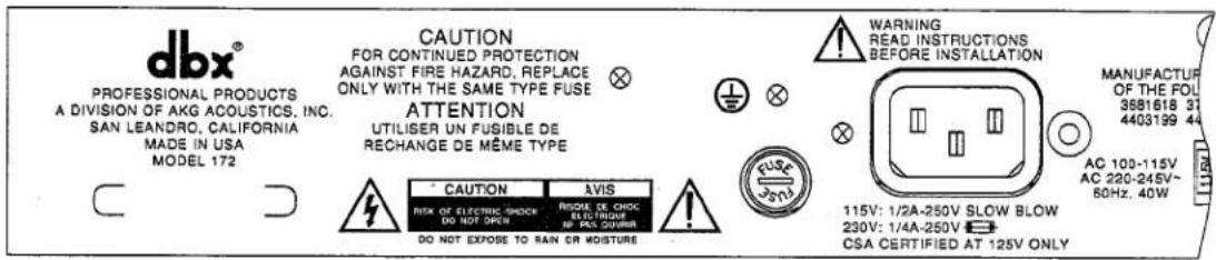
AC Cord: Plug into mains power. The 172 does not have a power switch. Unplug the SuperGate when not in use.

Warning: Be sure to verify both your actual line voltage and the voltage for which your Model 172 was set, as indicated on the rear panel of your unit. Connection to an inappropriate power source may result in extensive damage which is not covered by the warranty.
Fuse: For safety, the fuse must be Slow-Blow, 12 -amp for 115V, or 14 -amp (250mA) "T" type for 230V.
AC VOLTAGE Switch: Set this button to 115V (for 90 - 130V operation) or 230V (for 200 - 250V operation).
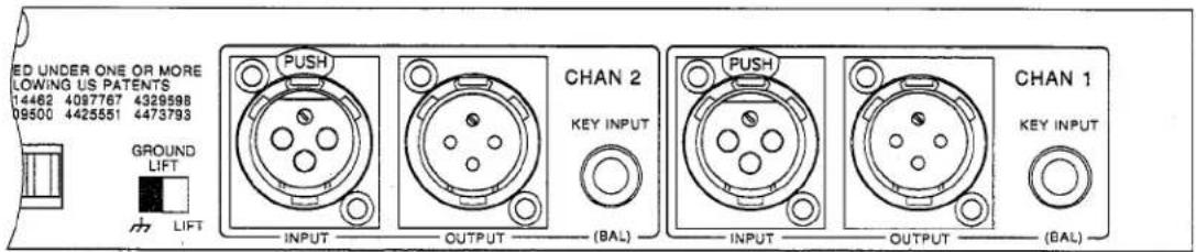
GROUND LIFT Switch: This button internally disconnects circuit ground from 172 chassis ground to eliminate any ground loop hum problems that may arise.
INPUT Jacks (CHAN 1 and CHAN 2): The 172's INPUT jacks accept either balanced or unbalanced signals. Nominal input level is +4dBu and clipping level is +24dBu. The INPUT jacks accept XLR-type connectors, wired pin 2 HOT (+) and pin 3 COLD (−). Pin 1 is connected to 172 chassis ground.
OUTPUT Jacks (CHAN 1 and CHAN 2): The 172's OUTPUT jacks are driven by floating active-balanced amplifiers that simulate a true transformer output. This allows for the load at the OUTPUT to be either balanced with respect to ground, or single-ended to ground (unbalanced) with very little difference (less than 0.5dB) in output level.
Either pin 2 or 3 can be grounded in this manner. Ncrminal output signal level is +4dBu into 600Ω, and typical maximum output signal level is +25dBu into a balanced 600Ω. The OUTPUT jacks accept XLR-type connectors, wired pin 2 HOT (+), pin 3 COLD (−) and pin 1 chassis ground.
KEY INPUT Jacks (CHAN 1 and CHAN 2): Use 14 phone plugs to connect these inputs to either balanced or unbalanced key signals. Nominal input level is +0dBu and clipping level is +20dBu.
OPERATING NOTES
Gating
Gating Dry Percussive Sounds (e.g., Snare Drum, Kick Drum)
Start with the following settings:
| KEY FILTER | Off |
| KEY EXTERNAL | Off |
| KEY MONITOR | Off |
| TCM | On |
| ONE SHOT | Off (On for Snare Drum) |
| Mode | GATE (If GATE is On, by default and 3-way switch, EXPAND and DUCK will be Off) |
| BYPASS | Off |
| THRESHOLD (db) | +10dB (3:00) |
| RATIO | Not Applicable in GATE mode |
| ATTACK (Sec) | 1mSec (12:00) |
| HOLD (Sec) | 0 (Off) or very short |
| RELEASE (dB/Sec) | 1000dB/S (between 8:00 and 9:00) |
| DEPTH (dB) | 45dB (12:00) |
These settings are primarily effective for gating percussive sounds with a high level initial transient. The input to the 172 is set to be less sensitive to nearby signals that would cause the gate to open or to "chatter." Once a signal falls under the THRESHOLD, the fast RELEASE setting will enable the gate to close very quickly. Use the HOLD control (in combination with RELEASE) to shape the envelope of the scund.
Note: Fast gating of sustained low frequency signals can result in "chattering." Because the 172 is capable of extremely fast gating, make sure the combined HOLD and RELEASE times are longer than the period of one full cycle of the gated signal's fundamental frequency. To eliminate any "chattering" simply adjust either the HOLD or RELEASE times to a longer time or slower rate. The proper THRESHOLD setting will also minimize false triggering and "chattering."
Generally, when a dry sound is called for, use the fastest RELEASE rate practical. Similarly for ATTACK settings, especially with instruments that have fast attacks (such as percussion), use the fastest setting that sounds best to your ears. Note that too fast an ATTACK can create clicks (as on a bass drum track). If an unwanted click, or other unwanted sound is produced, try a slower setting.
This type of quickly opened and closed gating is used to tighten up drum tracks; remove the "ring" from some drums; gate out the leakage of one drum through another's mic (See "Using the KEY FILTER to Gate Out Specific Frequencies" on the following page). These settings will not work well for a crash cymbal or a piano which have more decay after the initial transient (refer to the next page).
Gating Sounds That Have Longer Decay (e.g., Cymbal, Piano)
Start with the following settings:
| KEY FILTER | Off |
| KEY EXTERNAL | Off |
| KEY MONITOR | Off |
| TCM | On |
| ONE SHOT | Off |
| Mode | GATE or EXPAND |
| BYPASS | Off |
| THRESHOLD (db) | -20dB (12:00) |
| RATIO | Not Applicable in GATE mode |
| ATTACK (Sec) | 1mSec (12:00) |
| HOLD (Sec) | 1 Second (3:00) |
| RELEASE (dB/Sec) | 10dB/S (3:00) |
| DEPTH (dB) | 45dB (12:00) |
These settings allow lower level signals to open the gate, while the long HOLD and RELEASE settings allow the gate to remain open to capture the entire envelope of the signal.
The HOLD control is especially useful when set to allow a piano or guitar to fade naturally without truncating the signal or when set to capture the natural ring or reverb as it is trailing off after an initial snare drum hit. In either case, in order to capture the entire envelope naturally, it will be necessary to use the RELEASE control in conjunction with the HOLD control.
Note that using a longer HOLD time with a shorter RELEASE time can create some interesting special effects.
Using the KEY FILTER to Gate Out Specific Frequencies
The 172's Key Filters can zero in on and eliminate unwanted signals that other gates cannot. These fourth-order slope Key Filters are twice as selective as most other gates and their quasi-parametric controls provide quick and easy setup. Whether you need to key the gate from the click of a drum beater as it strikes the kick drum head, or isolate a kick drum from the high frequency energy of a snare, the 172 will do the job. Just follow these steps:
- Select KEY MONITOR and KEY FILTER.
- Start with the WIDTH control at about 9:00.
- Move the FREQUENCY control until you find the signal you want to gate out.
- Reduce the WIDTH control to isolate the signal as much as possible.
- Turn KEY MONITOR Off.
- Set the ENVELOPE and DEPTH controls as needed.
Expanding
Reducing Noise Under Smooth Sounds (Vocals, Woodwinds)
Start with the following settings:
| KEY FILTER | Off* |
| KEY EXTERNAL | Off |
| KEY MONITOR | Off |
| TCM | Off* (Do not use) |
| ONE SHOT | Off* |
| Mode | EXPAND |
| BYPASS | Off |
| THRESHOLD (db) | -20dB (center) |
| RATIO | 2:1 (12:00) |
| ATTACK (Sec) | 1mSec (12:00) |
| HOLD (Sec) | 400mSec (12:00) |
| RELEASE (dB/Sec) | 100dB/Sec (12:00) |
| DEPTH (dB) | 45dB (12:00) |
*We do not recommend using Key Filters, TCM or OneShot while in EXPAND mode.
Use the 172's EXPAND mode to reduce noise under smooth sounds like vocals and wind instruments. Properly set, most of the music should be above THRESHOLD and therefore unaffected, while background noise is downward expanded at whatever RATIO is selected. When expanding, you will almost always use 100mS or more of HOLD. This, together with the ATTACK, RELEASE and DEPTH controls will allow you to get the right amount of smoothness. The higher the THRESHOLD setting, the more the signal will be affected. Unnatural dynamic effects can be created this way. If high ratios are used, the effect is very much like gating.
Expansion is often very difficult to get just right. The 172 offers more high resolution control than any other gate, so be patient and you will get your sound.
Ducking
Using the 172's Duck Mode
Start with the following settings:
| KEY FILTER | Off |
| KEY EXTERNAL | Off |
| KEY MONITOR | Off |
| TCM | On |
| ONE SHOT | Off (Do not use) |
| Mode | DUCK |
| BYPASS | Off |
| THRESHOLD (db) | -20dB (center) |
| RATIO | Not Applicable in DUCK mode |
| ATTACK (Sec) | 1mSec (12:00) |
| HOLD (Sec) | 400mSec (12:00) |
| RELEASE (dB/Sec) | 100d3/Sec (12:00) |
| DEPTH (dB) | 45dB (12:00) |
Ducking is most often used in broadcasting applications to automatically attenuate crowd noise, music or a phone caller's voice when a host or announcer speaks. The primary signal (e.g., an announcer's voice) goes into the KEY INPUT, and the secondary signal (e.g., crowd noise) goes into the main INPUT. Normally the primary signal and the "ducked" secondary signal are combined with a mixing board. If needed, the primary signal can be gated with Channel 1 of the 172 and also used to control the ducking of the secondary signal with Channel 2. This would involve a "Y" cable so that the primary signal goes to both the Channel 1 INPUT and Channel 2 KEY INPUT.
The 172's Envelope controls provide full control of the gain reduction and gain recovery of the attenuated signals. THRESHOLD sets the level of the primary signal above which the secondary signal is attenuated. ATTACK sets the rate at which the secondary signal is attenuated; and HOLD sets the amount of time after the primary signal goes away (announcer stops talking) that the secondary signal is unattenuated. Accordingly, RELEASE sets the rate at which the secondary signal is unattenuated, and DEPTH sets the amount of attenuation in decibels. The RATIO control is inactive. You will probably want to use a lot of HOLD (e.g., 500mSec), a fairly slow RELEASE rate and a moderate DEPTH (maybe 6dB to 20dB) to get a smooth transition between the two signals.
It is not necessary to press the KEY EXTERNAL button; this happens automatically when you select DUCK mode. The KEY FILTER can be used to better isolate the primary signal, but is usually not necessary.
CONNECTING THE 172 TO YOUR SYSTEM
Basic Connection
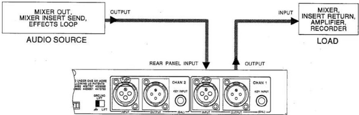
The 172 can be used with any line-level device. Some common examples include: mixing consoles, musical instruments, patch bays, and signal processors. For more specific cabling information, refer to Installation Considerations on the following page.
flowchart
graph LR
    A["AUDIO SOURCE"] -->|MIXER OUT, MIXER INSERT SEND, EFFECTS LOOP| B["OUTPUT"]
    B --> C["REAR PANEL INPUT"]
    C --> D["OUTPUT"]
    D --> E["LOAD"]
    F["MIXER, INSERT RETURN, AMPLIFIER, RECORDER"] --> G["INPUT"]
    G --> H["OUTPUT"]
    H --> I["CHAN 1"]
    I --> J["OUTPUT"]
    J --> K["CHAN 2"]
    K --> L["OUTPUT"]
    L --> M["Ground Lift"]
    M --> N["PUSH"]
    N --> O["OUTPUT (BAL)"]
    O --> P["CHAN 1"]
    P --> Q["OUTPUT (BAL)"]
172 REAR PANEL

For all connections, refer to the following steps:
-
Turn Off all equipment before making any connections.
-
Mount the 172 in a 1U rack space (optional).
The 172 requires one rack space (height) and 1 rack space (width). It can be mounted above or below anything that doesn't generate excessive heat, since it requires no special ventilation. Ambient temperatures should not exceed 113°F (45°C) when equipment is powered.
Note: Avoid over-tightening of rackmounting screws as this could damage the front panel.
Caution: Never remove the cover. There are no user-serviceable parts inside, and you run the risk of an electric shock.
- Make connections via XLR jacks (or Phone jacks for KEY INPUT) according to your requirements.
Typical patch points include: a mixer's channel or subgroup inserts when using the 172 on individual instruments or tracks; the mixer's main outputs when mixing; an instrument preamp's effects loop when using the 172 for guitar or bass; main outs of a submixer (i.e., keyboard mixer) as the signal is sent to main mixer; between a DAT's output and an analog cassette input. When using a chain of processors, the 172 may be placed either before or after effects or dynamics processors. We recommend you use common sense and experiment with different setups to see which one provides the best results for your needs.
4. Plug in the AC power cable to power On the unit.
Multi-Channel Connections
The 172 can be set for 2-channel stereo operation by pressing the MASTER button In. This will force Channel 2 (CHAN 2) to act as a slave and track Channel 1 (CHAN 1) to preserve proper stereo imaging. KEY FILTER controls and BYPASS remain independent.
Remember, the 172's two channels operate completely independently when the MASTER button is not pressed In.
Key Input Connections
To control the 172 gate by signals other than the audio input (via an auxiliary device), connect the auxiliary device's output to the 172's KEY INPUT jack, and feed the auxiliary device's input with the same signal fed to the 172's Signal Input. Make connections with 14 Phone plugs.
INSTALLATION CONSIDERATIONS
Input/Output Cable Configurations
Hookups and Cabling
The 172 is designed for nominal +4dBu levels at its XLR jacks and its KEY INPUT Phone jacks. Inputs can be used with either balanced or unbalanced sources and outputs can be used with either balanced or unbalanced loads, provided you use proper cabling.
A balanced line is defined as two-conductor shielded cable with the two center conductors carrying the same signal but of opposite polarity with respect to ground. An unbalanced line is generally a single-conductor shielded cable with the center conductor carrying the signal and the shield at ground potential.
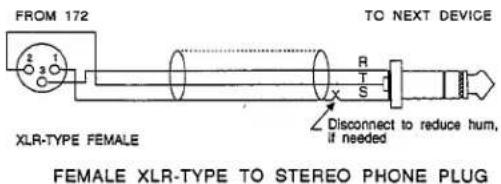
Note: Most balanced (3-conductor) cables have the shield connected at both ends. This can result in ground loops which cause hum. If hum is a problem, try changing the position of the rear panel GROUND LIFT switch. If hum persists, try disconnecting the shield on one or more of your cables, preferably at the input of a device, not at the output. The shield is pin 1 on the XLR, sleeve on a 14 " TRS.
Connecting Audio Inputs
The following figures show cables for connecting balanced and unbalanced signal sources to the 172 audio inputs. Refer to the type of operation and connectors you are using.
The XLR input connectors on the 172 can be driven with either balanced or unbalanced signal lines up to +24dBu maximum with excellent results. The input impedance depends on the balance of the driving signal with respect to circuit ground of the 172. If the signal is balanced with respect to 172 circuit ground, the input impedance is 22kΩ. If the signal is single-ended (unbalanced) to 172 circuit ground, the input impedance is 18.5kΩ.
The XLR input connectors, which are in phase with the XLR output connectors, are wired pin 2 HOT (+) and pin 3 COLD (−).
A rear panel GROUND LIFT switch is provided on the 172 to either connect circuit ground to chassis ground, or leave circuit ground "floating." Try flipping this switch if you have hum.
Connecting Audio Outputs
The following figures show cables for connecting the 172 audio outputs to balanced and unbalanced loads. Refer to the type of operation and connectors you are using.
The XLR output connectors of the 172 can drive either balanced or unbalanced lines with excellent results. Typical driving capability into a balanced 600Ω load is +24dBu, and into an unbalanced 600Ω load is +21dBu. In either case, output impedance is 30Ω. Due to the floating characteristic of the active electronic output amplifiers, it is unnecessary to use transformers at the outputs. The XLR output connectors, which are in phase with the XLR input connectors, are wired pin 2 HOT (+) and pin 3 COLD (−).


Input Connections (Unbalanced Operation)


Input Connections (Balanced Operation)


Output Connections (Unbalanced Operation)

Output Connections (Balanced Operation)
Connect KEY Inputs (if required)
The following figures show cables for connecting balanced and unbalanced signal sources to the 172's KEY INPUT. Refer to the type of operation and type of connector you are using.
Both sets of inputs are electronically balanced. The input impedance is 22kΩ balanced and 18.5kΩ unbalanced, allowing operation from virtually any source. Nominal operating level is +4dBu, and can be set for levels ranging from -14dBu to +19dBu. The input connectors are TRS 14 " phone jacks, Tip Hot (+), Ring Cold (-).

MONO PHONE PLUG TO STEREO PHONE PLUG

PHONO PLUG TO STEREO PHONE PLUG
Key Input Connections (Unbalanced Operation)
Notes for using 1/4" Mono Phono Connectors:
Connect the Sleeve to the cable's shield. In an emergency, 14 " Mono Phone cables will work.

XLR-TYPE FEMALE
FEMALE XLR-TYPE TO STEREO PHONE PLUG
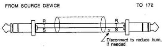
STEREO PHONE PLUG TO STEREO PHONE PLUG
Key Input Connections (Balanced Operation)
Grounding
Note: For maximum hum rejection, avoid common grounding at the 172's input and output. The best starting point is to ground the shield of the input cable at the source device (leaving it unconnected at the 172) and to ground the shield of the output cable to the ground terminal of the 172 (leaving it unconnected at the receiving device).

SIGNAL FLOW Signal Flow (Balanced Connection)
TECHNICAL SUPPORT, FACTORY SERVICE
Technical Support, Factory Service
The 172 is an all-solid-state product with components chosen for high performance and excellent reliability. Each 172 is tested, burned in and calibrated at the factory and should require no internal adjustment of any type throughout the life of the unit. We recommend that your 172 be returned to the factory only after referring to the manual and consulting with Customer Service.
Our phone number, fax number and address are listed on the inside front cover. When you contact dbx Customer Service, be prepared to accurately describe the problem. Know the serial number of your unit — this is printed on a sticker attached to the rear panel.
Note: Please refer to the terms of your Limited Two-Year Standard Warranty, which extends to the first end-user. After expiration of the warranty, a reasonable charge will be made for parts, labor, and packing if you choose to use the factory service facility. In all cases, you are responsible for transportation charges to the factory. dbx will pay return shipping if the unit is still under warranty.
Shipping Instructions: Use the original packing material if it is available. Mark the package with the name of the shipper, and with these words in red: DELICATE INSTRUMENT, FRAGILE! Insure the package properly. Ship prepaid, not collect. Do not ship parcel post.
Registration Card and User Feedback
We appreciate your feedback. After you have an opportunity to use your new 172, please complete the Registration Card (located at the back of this manual), detach it from the manual and return it.
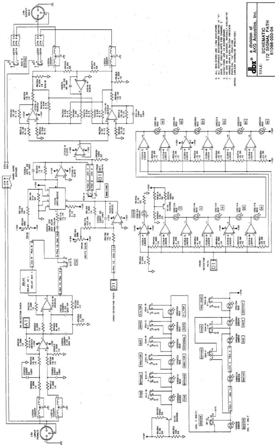
SCHEMATICS
Schematics for certain portions of the 172 circuitry are provided on the following pages. If you require complete 11" x 17" schematics and assembly drawings, contact our Customer Service Department for information on obtaining dbx Service Manuals.
SPECIFICATIONS
Note: 0dBV = 1.0Vrms; 0dBu = 0.775Vrms
Specifications are subject to change.
| Input | |
| Rear Panel | |
| Audio Input Impedance | 22kΩ; Balanced; 18.5kΩ; Unbalanced |
| Maximum Audio Input Level | +24dBu |
| Connector Type | XLR (Female) |
| Key | |
| Key Input | 22kΩ; Balanced; 18.5kΩ; Unbalanced |
| Maximum Key Input | +24dBu |
| Key Input Connector Type | 14 " TRS Phone Jack |
| Output | |
| Rear Panel | |
| Output Source Impedance | 30Ω: Balanced |
| Minimum Load Impedance | 600Ω |
| Maximum Output Level | +24dBu into 600Ω; |
| Connector Type | XLR (Male) |
| Frequency Response | 20Hz - 20kHz, ±0.5dB |
| THD | <0.02%, 1kHz, Unity Gain, Typ. <0.1%, 20Hz - 20kHz |
| Equivalent Input Noise | -90dBu, Unweighted |
| Dynamic Range | 114dB |
| Minimum Attack Time | <5μs |
| Release Time | 10ms - 10 Seconds (to 30dB Attenuation) |
| Threshold Range | -60dBu to +20dBu |
| Threshold Characteristic | Hard Knee |
| Attenuation | Adjustable, 0dB to 90dB |
| Hold Time | Adjustable, 0dB to 3 Seconds |
| Operating Voltage | DO: 100 - 125VAC, 50/60HzEU: 200 - 240VAC, 50/60Hz |
| Power Consumption | 40W |
| Operating Temperature | 0°C to 45°C (32°F to 113°F) |
| Dimensions (H x W x D) | 1.75" x 19" x 9.5" (4.45cm x 48.5cm x 24.5cm) |
| Rack Space | 1 Rack Unit, Full Width |
| Weight | Net Weight: 8.25 lbs (3.8 kg)Shipping Weight: 11 lbs (5 kg) |
| Warranty | dbx Standard Two-Year Warranty |


| dbx® a division ofAKG Acoustics, Inc. |
| TITLE: SCHEMATIC172 HOLD TIMER61098-000-04 |
- AIRBORS NEAR EACH SWITCH INDICATE THE PHYSICAL "IN" POSITION
- RESISTORS ARE 1/8W MINIATURE
- CAPACITORS ARE IN MICROFARADS
- ALL REFERENCE DESIGNATORS ENDING IN "A" HAVE "B" EQUIVALENTS FOR CHANNEL 2 NOTES: (UNLESS OTHERWISE SPECIFIED)
Registration Card
Model # ____ Serial # ____ Purchase Date ____
Your name ____ Title ____
Company Telephone
Street
City, State, Mail Code (Zip), Country ____
Purchased from ____ Price ____
Nature of your product application
Please rate the following from 1 to 10 (where 10 is the best possible rating and 1 is the lowest):
Performance____Ease of use____Documentation____Cosmetics____Serviceability____
Comments
Please list the magazines you read most often, in order of priority ____

BUSINESS REPLY MAIL
FIRST CLASS MAIL PERMIT NO 2445
SAN LEANDRO CA
POSTAGE WILL BE PAID BY ADDRESSEE
ATTN CUSTOMER SERVICE
dbx A DIVISION OF AKG ACOUSTICS INC
1525 ALVARADO STREET
SAN LEANDRO CA 94577-9810 USA
NO POSTAGE
NECESSARY IF
MAILED IN THE
UNITED STATES

natural_image
Abstract pattern of black horizontal lines on white background (no text or symbols)United States Warranty
Limited Warranty
This warranty is valid only for the original purchaser and only in the United States. We warrant dbx products against defects in material or workmanship for a period of two years from the date of original purchase for use, and agree to repair or, at our option, replace any defective item, except external power transformers, without charge for either parts or labor.
IMPORTANT: This warranty does not cover damage resulting from accident, misuse or abuse, lack of reasonable care, the affixing of any attachment not provided with the product, loss of parts, or connecting the product to any but the specified receptacles. This warranty is void unless service or repairs are performed by an authorized service center. No responsibility is assumed for any special, incidental or consequential damages. However, the limitation of any right or remedy shall not be effective where such is prohibited or restricted by law.
Simply take or ship your dbx product prepaid to our service department. Be sure to include your sales slip as proof of purchase date. (We will not repair transit damage under the no-charge terms of this warranty.) dbx will pay return shipping.
NOTE: No other warranty, written or oral is authorized for dbx products.
This warranty gives you specific legal rights, and you may also have other rights which vary from state to state. Some states do not allow the exclusion of limitations of incidental or consequential damages or limitations on how long an implied warranty lasts, so the above exclusion and limitations may not apply to you.
International Warranty
Bedingungen
dbx warrants dbx products (except for external power transformers) against evident defects in material and workmanship for a period of two years from the date of original purchase for use. This warranty does not cover damage resulting from misuse or abuse, or lack of reasonable care, and inadequate repairs performed by unauthorized service centers. Performance of repairs or replacements under this warranty is subject to proof of purchase. Shipment of the defective item for repair under this warranty will be at the customer's own risk and expense. This warranty is valid for the original purchaser only.
Conditions de garantie
- IMPORTANT SAFETY INSTRUCTIONS
- Safety Instructions (European)
- Safety Instructions (German)
- Safety Instructions (French)
- Safety Instructions (Spanish)
- Safety Instructions (Italian)
- QUICK SETUP
- INSPECTION
- Unpack and inspect the 172 package.
- INTRODUCTION
- The 172 SuperGate®
- Features
- Each channel includes:
- Applications
- The SuperGate is a useful tool for many audio applications. Use it to:
- OPERATING CONTROLS
- KEY Section (Channel 1 and 2)
- ENVELOPE Section: (Channel 1 and 2)
- OPERATING NOTES
- Gating Dry Percussive Sounds (e.g., Snare Drum, Kick Drum)
- Gating Sounds That Have Longer Decay (e.g., Cymbal, Piano)
- Using the KEY FILTER to Gate Out Specific Frequencies
- Reducing Noise Under Smooth Sounds (Vocals, Woodwinds)
- Using the 172's Duck Mode
- CONNECTING THE 172 TO YOUR SYSTEM
- Basic Connection
- Plug in the AC power cable to power On the unit.
- Multi-Channel Connections
- Key Input Connections
- INSTALLATION CONSIDERATIONS
- Input/Output Cable Configurations
- Hookups and Cabling
- Connecting Audio Inputs
- Connecting Audio Outputs
- Connect KEY Inputs (if required)
- Key Input Connections (Unbalanced Operation)
- Key Input Connections (Balanced Operation)
- Grounding
- TECHNICAL SUPPORT, FACTORY SERVICE
- Registration Card and User Feedback
- SCHEMATICS
- SPECIFICATIONS
- Registration Card
- BUSINESS REPLY MAIL
- United States Warranty
- Limited Warranty
- International Warranty
- Bedingungen
- Conditions de garantie
Brand : DBX
Model : 172
Category : Professional audio equipment