
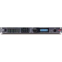
F-900A - Professional audio equipment DBX - Free user manual and instructions
Find the device manual for free F-900A DBX in PDF.


| Product Type | Audio Signal Processor |
| Brand | DBX |
| Model | F-900A |
| Dimensions (W x H x D) | 19 x 1.75 x 6.5 inches (standard rack unit) |
| Weight | 5.5 lbs (2.5 kg) |
| Power Requirements | 100-240 VAC, 50/60 Hz, 15W |
| Audio Input Type | Balanced XLR and 1/4" TRS |
| Audio Output Type | Balanced XLR and 1/4" TRS |
| Frequency Response | 20 Hz - 20 kHz ±0.5 dB |
| Dynamic Range | >110 dB |
| Signal-to-Noise Ratio | >100 dB |
| Total Harmonic Distortion | <0.01% |
| Processor Type | DSP-based |
| Primary Functions | Compression, Limiting, Gate, EQ, De-essing |
| Presets | Factory presets and user-programmable |
| Display | LCD screen with menu navigation |
| Control Interface | Front panel knobs, buttons, and encoder |
| Connections | MIDI In/Out, USB for firmware updates |
| Construction | Steel chassis, rack-mountable |
| Operating Temperature | 32°F to 104°F (0°C to 40°C) |
| Storage Temperature | -4°F to 140°F (-20°C to 60°C) |
| Included Accessories | Power cord, user manual, rack ears |
Frequently Asked Questions - F-900A DBX
User questions about F-900A DBX
0 question about this device. Answer the ones you know or ask your own.
Ask a new question about this device
Download the instructions for your Professional audio equipment in PDF format for free! Find your manual F-900A - DBX and take your electronic device back in hand. On this page are published all the documents necessary for the use of your device. F-900A by DBX.
USER MANUAL F-900A DBX
dbx Professional Products
User/Operator Description
Introduction
Congratulations on purchasing the dbx F-900A mainframe. Your new F-900A powered mainframe can hold up to nine dbx 900 series modules (as well as those of some other companies).
This owner's manual provides you with the steps you need to connect power to the F-900A and install it with 900-series modules. Basic troubleshooting information is included. For more detailed technical information, a service manual is available by order.
This manual also includes important information for completing the warranty card, supporting your F-900A with dbx customer and factory service, and forms for ordering 900 series service manuals and additional dbx binders.
Table Of Contents
| page | contents |
| 1 | Introduction |
| 2 | Unpacking |
| 3 | Registration Card, Warranty, Feedback |
| 3 | Registration Card |
| 3 | Warranty |
| 3 | User Feedback Form |
| 4 | Installation |
| 10 | Troubleshooting |
| 10 | How to remove the power supply. |
| 11 | Technical Support, Factory Service |
| 11 | Technical Support |
| 11 | Factory Service |
| 11 | Shipping Instructions |
| 12 | Technical Data |
| 12 | Specifications |
| 12 | Schematics |


Unpacking
1. Unpack and inspect. (recommended)
Your F-900A powered mainframe was carefully packed at the factory in a protective carton. Nonetheless, be sure to examine the unit and the carton for any signs of damage that may have occurred during shipping.
If obvious physical damage is noticed contact the carrier immediately to make a damage claim.
Do not destroy the carton or packing material.
Packed with the F-900A and this owner's manual are:
1 Warranty Certificate (includes Registration Card)
1 Line Cord
1 dbx Binder (to support manuals for F-900A mainframe and 900-series modules)
2. Please complete the Registration Card and return it.
Refer to the following page.
NOTE: We do not sell or pass on information provided from the Registration Card to other companies.
Registration Card, Warranty, Feedback
Registration Card
There are two good reasons for returning the Registration Card shipped with this product.
1) It enables us to inform you of new applications, performance improvements, and service aids that are developed, and
2) It helps us respond promptly to claims under warranty without having to request a copy of your bill of sale or other proof of purchase.
Please fill in the Registration Card, detach it from the Warranty Certificate, and send the card to us today. If it is lost (or you have purchased this unit used), please photocopy the duplicate below, fill it in, and send it to the address on the inside of the front cover.
| Registration Card | |
| Model # Serial # Purchase Date | |
| Your name Title | |
| Company Telephone | |
| Street | |
| City, State, Mail Code (Zip), Country | |
| Purchased from Price | |
| Nature of your product application | |
| Please rate the following from 1 to 10 (where 10 is the best possible rating, and 1 is the lowest): | |
| Performance Ease of use Documentation Cosmetics Seviceability | |
| Comments | |
| Please list the magazines you read most often, in order of priority | |
| 95078-000-01 March 1990 |
Warranty
The warranty which can be enjoyed only by the first end-user of record, is stated on the separate Warranty Certificate packed with this manual. Save it for future reference. Details on obtaining factory service are provided on page 11.
User Feedback Form
We are very interested in your comments about this product. Your suggestions for improvement to either the product or the manual will be certainly reviewed. A postpaid User Feedback Form is provided in the back of this manual for your convenience. If it is missing, please write to us at the address on the inside of the front cover. Thank you.
1. Connect Power
Ordinarily, your unit will have been shipped with the mains voltage switch set for your country, the plug will be suitable, and the fuse will be of the correct value. BUT, PLEASE CHECK IN EVERY CASE. Your unit may have reached you via an unexpected route or may have been changed in transit.
A. Locate the voltage selector switch on the rear panel. See Fig 1.
B. Check that the voltage selector switch is set correctly. To change the setting, slide the switch so that the correct voltage label is in view (115V or 230V).
The F-900A is shipped ready for 115-volt, 50/60Hz operation — unless a label on the power cord indicates otherwise. If you change the setting of the voltage selector switch, be sure to also change the fuse. Use a 3AG 250V Slow-Blow fuse ( 34 -amp for 115-volt operation, 38 -amp for 230-volt operation).
North American 14 " x 114 " fuses are normally supplied since they are available in almost every country. If more convenient, the fuseholder may be easily converted to 5 x 20mm European fuses by use of an adapter available at no cost from the factory at the address shown on the front page of this manual. If you convert the fuseholder to support European fuses, use a 250V Type T fuse (.8-amp for 115-volt operation, .315-amp for 230-volt operation).
C. Connect the F-900A's power cord to an appropriate AC power source.
The power cord is ordinarily terminated in a 'U-ground' plug (USA standard), unless specially-ordered for your country's standard. The green (or green/yellow) wire from the safety-ground prong is ordinarily connected directly to the F-900A chassis. If it becomes necessary to lift this ground to suppress ground loops, do so with a three-prong to two-prong adapter plug, rather than by damaging the power plug. You should not defeat the ground unless absolutely necessary, because it eliminates the intrinsic safety feature of the three-wire system.
WARNING: If you are not thoroughly familiar with the technique for changing the plug, ask a qualified electrical technician to change plugs, or purchase a new IEC mains cord with the correct plug attached.
WARNING: If the ground is defeated, certain fault conditions in the unit or in the system to which it is connected can result in full line voltage between chassis and earth ground. Severe injury can then result if the chassis and earth ground are touched simultaneously.

Fig 1: F-900A Rear Panel

| CONDUCTOR | WIRE COLOR | ||
| Normal | Alt | ||
| L | LINE | BROWN | BLACK |
| N | NEUTRAL | BLUE | WHITE |
| E | EARTH GND | GREEN-YELLOW | GREEN |
Fig 2: AC Power Cord Color Coding
2. Consider the location of the F-900A and Heat Management
A fully loaded frame can produce up to 75 watts of heat. The F-900A frame and its modules have been engineered to be operated in an environment where there is ample free air available at the underside of the unit and where the air is cooler than 50°C (122°F).
If, for example, you install your frame in a rack above heat-producing equipment (such as vacuum tube amplifiers), you must carefully consider the thermal sources and the air flow characteristics of the installation to avoid creating reliability problems due to overheating.
Be sure that free air is available to every heat-producing unit in the rack. One way to do this is to allow ample airspace between units. Some users install grille panels to permit heated air to escape more easily.
In racks that must be densely packed, it may be necessary to install fans to force air upward rapidly to cool all units, especially the topmost ones.
U.S. Sources of rack-mounted fan assemblies include:
Unitrack, 1372 Enterprise Drive, West Chester, Pennsylvania 19380 (212) 692-0800
McLean Engineering, Princeton Junction, New Jersey 08550 (609) 799-0100 (also makes filter grille panels)
NOTE: The inclusion of these products is not an endorsement or brand recommendation.
3. Prepare Modules for Installation — Check Supply Current Requirements
Table 1 lists all 900 series modules existing at the time of publication with corresponding supply currents. Some modules included in this list are no longer being produced.
When installing future dbx modules (as well as third party modules) consult the manual which accompanies each module, to be certain you are operating within the capacity of the F-900A's power supply.
NOTE: The 15 volt rails are used for processing; the 24 volt rails are used for output drivers in order to obtain +24dBm into 600 ohms.
A. Check the supply current ratings (+15V, -15V, +24V, -24V) for each module you intend to install.
B. Verify that the total supply current required for each voltage bus does not exceed capacity.
NOTE: +15V bus capacity = 1000mA; -15V bus capacity = 1000mA; +24V bus capacity = 555mA; -24V bus capacity = 500mA.
Table 1: Module Current Requirements
| Module # | Product Name | Regulated +15V -15v | Unregulated +24V -24V | ||
| 902 | De-Esser | 60mA | 60mA | 30mA | 30mA |
| 903 | Compressor/Limiter | 60mA | 60mA | 30mA | 30mA |
| 904 | Noise Gate | 60mA | 60mA | 30mA | 30mA |
| 905 | Parametric EQ | 100mA | 100mA | 30mA | 30mA |
| 906* | Flanger (2-rack spaces) | 200mA | 200mA | 30mA | 40mA |
| 907* | Compressor/Limiter | 50mA | 50mA | 20mA | 20mA |
| 911 | Type I NR | 50mA | 50mA | 26mA | 26mA |
| 929 | Hiss Reducer | 75mA | 75mA | 65mA | 65mA |
| 933 | Distribution Amp/Mixer | 60mA | 60mA | 90mA | 90mA |
| 941* | Type II NR Dual Encode | 50mA | 50mA | 30mA | 30mA |
| 942* | Type II NR Dual Decode | 50mA | 50mA | 30mA | 30mA |
| 941A | Type II NR Dual Encode | 50mA | 50mA | 26mA | 26mA |
| 942A | Type II NR Dual Decode | 50mA | 50mA | 26mA | 26mA |
| 408* | Type II NR Decode | 40mA | 40mA | 20mA | 20mA |
| 409* | Disc Decoder | 40mA | 40mA | 20mA | 20mA |
| 410* | Type I NR Encode/Decode | 50mA | 50mA | 30mA | 30mA |
| 411* | Type I NR Encode/Decode | 50mA | 50mA | 30mA | 30mA |
* Indicates Discontinued Modules

4. Install Modules
Modules are simply pushed into the desired slot. The F-900A can support up to nine modules. Unlike previous versions of the 900-series frame, the ninth position on the F-900A is identical to positions 1-8 and has a full I/O connections strip on the back panel.
Every slot is wired identically to the rear panel and to the power supply. (See Table 2)
As with any equipment which is densely packaged and which has a common power supply, it is possible that low-level hum, noise and crosstalk characteristics will vary with the arrangement of modules. These effects should be insignificant in well-designed practical installations even though they may be measureable in the laboratory.
A. Turn the power off.
B. Simply line up the module card and the guide rails, then gently slide the module into place until it seats in the connector. Repeat this procedure for each module you want to install.
C. The screws may be tightened for permanent installations, but you may wish to leave them loose temporarily until you have chosen the final arrangement of the modules and have marked their positions on the floor of the frame using a white grease pencil or paper labels. Thus, when modules are removed in the future, you can put them back in the correct sequence.
5. Complete Wire Connections: Inputs, Outputs, Ground, Optional Stereo Coupling
The F-900A has nine available channels, labeled CH 1 through CH 9, to support up to nine modules. Each module is connected to channel terminals located on the rear of the F-900A (Figure 1) according to Table 2. The terminal screws are #6-32 and have a diameter of 0.138" (3.5mm). They are spaced on 0.375" (9.525mm) centers.
NOTE: If you mount the F-900A in a rack, be sure to leave plenty of slack in the wiring in case you need to slide the unit out of the rack to remove the power supply. (See power supply removal instructions on page 10.)
A. Locate the F-900A terminal strips on the rear panel. These input/output barrier strips provide audio and control voltage (CV) connections for the nine modules.
B. Check Table 2 for each module you have installed and connect inputs and outputs according to each module's connection scheme. We recommend using 2-conductor shielded cable such as Belden 8451.
NOTE: See individual instruction manuals for modules not shown.
C. Complete ground connections.
Connect the circuit ground to chassis ground (if necessary). The chassis ground and circuit ground are not initially connected. In some systems it may be desirable to connect the circuit ground to the chassis ground. This may be accomplished using the chassis ground terminal on the rear panel and any one of the circuit ground terminals on a barrier strip. Since all circuit grounds are common among all modules, when the circuit ground of one module is connected to chassis ground, the circuit ground of each installed module is connected to chassis ground.
Table 2: Hookup Information*
| F-900A Terminals | 902 De-Esser | 903/907 Comp/Limiter | 904 Noise Gate | 905 Parametric | 906 Flanger | 929 Hiss Reducer | 941/941A 942/942A Type II NR | 408 Type II NR | 409 Disc Decoder | 410/411/911 Type I NR |
| + ] A - ] = + ] B - ] | Audio Input | Input | Ch. A Input | Ch. A Input | Input | Decode Input | ||||
| Audio Output | Output | Ch. A Output | Ch. B Output | Master Gain | Encode Output | |||||
| Not Used | ||||||||||
| + ] C - ] = + ] D - ] | Not Used | Detector Input (907: AUX IN) | Key Input | Not Used | Ext. CV Input | Ch. B Input | Ch. B Input | Not Used | Encode Input | |
| Remote Bypass | ||||||||||
| Control Voltage Output | Not Used | Mix Output | Ch. B Output | Ch. A Output | Output | Decode Output | ||||
| Control Voltage Input | ||||||||||
* Audio Output negative (-) terminals are internally connected to circuit ground.
Technical Support, Factory Service
Technical Support
If you require technical support, contact dbx customer service. Be prepared to accurately describe the problem. Know the serial number (and 'M' number, if any) of your F-900A — these are printed on a label attached to the rear of the F-900A unit.
| Telephone: | (1) 415/351-3500 |
| or FAX: | (1) 415/351-0500 |
| or Telex: | 285481 |
or Write
Customer Service
dbx Professional Products
a division of AKG Acoustics, Inc.
1525 Alvarado Street
San Leandro, CA 94577
USA
Factory Service
Always contact Customer Service before returning a product to the factory for service. Often, a problem is relatively simple and can be quickly fixed after telephone consultation.
Products can be returned to the factory for service only after Customer Service has issued a Return Authorization number. This number flags the returned unit for priority treatment when it arrives on our dock, and ties it to the appropriate information file.
Please refer to the terms of your Limited Two-Year Standard Warranty, which extends to the first end-user. After expiration of the warranty, a reasonable charge will be made for parts, labor, and packing if you choose to use the factory service facility. In all cases, you are responsible for transportation charges to the factory. dbx will pay return shipping.
Shipping Instructions
Use the original packing material if it is available. If it is not, use a sturdy, double-walled carton no smaller than 22 x 16 x 8 inches (56 x 41 x 21 cm) with a minimum bursting test rating of 200 pounds (91 kg). Place the chassis in a plastic bag (or wrap it in plastic) to protect the finish, then pack it in the carton with at least 1.5 inches (4 cm) of cushioning on all sides of the unit. 'Bubble' packing sheets, thick fiber blankets, and the like are acceptable cushioning materials; foam 'popcorn' and crumpled newspaper allow the unit to shift in transit and will not protect it adequately. Wrap cushioning materials tightly around the unit and tape them in place to prevent the unit from shifting out of its packing. Close the carton without sealing it and shake vigorously. If you can hear or feel the unit move, use more packing. Seal the carton with 3-inch (8 cm) reinforced fiberglass or polyester sealing tape, top and bottom in an 'H' pattern. Narrower or parcel-post type tapes will not withstand the stresses applied to commercial shipments.
Mark the package with the name of the shipper, and with these words in red:
DELICATE INSTRUMENT, FRAGILE!
Insure the package properly. Ship prepaid, not collect. Do not ship parcel post. Your Return Authorization number must be shown on the label, or the package will not be accepted.
- User/Operator Description
- Introduction
- Unpacking
- Unpack and inspect. (recommended)
- Please complete the Registration Card and return it.
- Registration Card, Warranty, Feedback
- Registration Card
- Warranty
- User Feedback Form
- Connect Power
- VOLTAGE # SWITCH
- Consider the location of the F-900A and Heat Management
- Prepare Modules for Installation — Check Supply Current Requirements
- Install Modules
- Complete Wire Connections: Inputs, Outputs, Ground, Optional Stereo Coupling
- Complete ground connections.
- Technical Support, Factory Service
- Technical Support
- Factory Service
- Shipping Instructions
- DELICATE INSTRUMENT, FRAGILE!
Brand : DBX
Model : F-900A
Category : Professional audio equipment