
Redbox RB-DA6RG - Receiver Sonifex - Free user manual and instructions
Find the device manual for free Redbox RB-DA6RG Sonifex in PDF.


| Product Type | 6 Way Stereo Distribution Amplifier with Output Gain Control |
| Dimensions (Raw) | 48cm (W) x 10.8cm (D) x 4.2cm (H) (1U) |
| Weight | 1.3kg Nett, 1.9kg Gross |
| Power Supply | Filtered IEC, 110-120V or 220-240V, 6W max |
| Input Connections | 2 x XLR-3 female (balanced), 1 x RJ45 socket (balanced), 2 x RCA Phono (unbalanced) |
| Output Connections | 6 x RJ45 socket (balanced, can be wired unbalanced) |
| Input Selector | Switch to choose between XLR/RJ45 balanced or RCA unbalanced inputs |
| Stereo/Mono Mode | Recessed switch for 6 stereo outputs or 12 mono outputs |
| Output Gain Range | -8dB to +18dB per output via preset potentiometers (front panel accessible) |
| Frequency Response | 20Hz - 20kHz ±0.1dB (600Ω load, ref 1kHz) |
| Maximum Input Level | +28dBu |
| Maximum Output Level | +28dBu |
| Total Harmonic Distortion | 0.01% THD @ 1kHz, ref +8dBu output |
| Noise | -86dB unity gain ref +8dB |
| Common Mode Rejection | >66dB typically |
| Input Impedance (XLR) | >20kΩ balanced bridging |
| Input Impedance (RCA) | >20kΩ unbalanced |
| Output Impedance | <50Ω |
| Fuse Rating | Anti-surge 100mA (230VAC) or 200mA (115VAC), 20x5mm |
| Compatibility | StudioHub+ standard for RJ45 wiring |
| Power Indicator | Front panel LED |
| Rack Mounting | 1U, optional RK1/RK2 kits |
| Country of Manufacture | United Kingdom |
Frequently Asked Questions - Redbox RB-DA6RG Sonifex
User questions about Redbox RB-DA6RG Sonifex
0 question about this device. Answer the ones you know or ask your own.
Ask a new question about this device
Download the instructions for your Receiver in PDF format for free! Find your manual Redbox RB-DA6RG - Sonifex and take your electronic device back in hand. On this page are published all the documents necessary for the use of your device. Redbox RB-DA6RG by Sonifex.
USER MANUAL Redbox RB-DA6RG Sonifex
RB-DDA6A 6 Way Stereo AES/EBU Digital Distribution Amplifier
RB-DDA6A3 6 Way Stereo AES3 Digital Audio Distribution Amplifier
RB-DDA6S 6 Way Stereo S/PDIF Digital Distribution Amplifier
RB-DDA6A-2P 6 Way Stereo AES/EBU Digital Distribution Amplifier With Dual Power Supplies
RB-DDA6W 6 Way Word Clock Distribution Amplifier
RB-DDA6W-2P 6 Way Word Clock Distribution Amplifier With Dual Power Supplies
RB-DDA22 Digital Audio Distribution Amplifier With Multiple Outputs
RB-AES4B3 Quad 3 Way Passive AES3ID Splitters With BNC Connectors
RB-AES4X3 Quad 3 Way AES3 Splitter XLR Connectors
RB-MS4X3 Quad 3 Way Microphone Splitter
RB-MSP6 6 Way +48V Phantom Power Supply

Manufacturers of audio & video products for radio & TV broadcasters SONIFEX
Redbox Handbook 4
For the latest Sonifex handbook information please visit the Sonifex website at www.sonifex.co.uk
Redbox User Handbook No 4
Stock Code: 30-341
Artwork: AW10834
Revision 3.05, October 2020
©Sonifex Ltd, 2020
All Rights Reserved
Sonifex Ltd, 61, Station Road, Irthlingborough,
Northants, NN9 5QE, England.
Tel: +44 (0)1933 650 700
Fax: +44 (0)1933 650 726
Email: sales@sonifex.co.uk
Website: https://www.sonifex.co.uk
Information in this document is subject to change without notice and does not represent a commitment on the part of the vendor. Sonifex Ltd shall not be liable for any loss or damage whatsoever arising from the use of information or any error contained in this manual.
No part of this manual may be reproduced or transmitted in any form or by any means, electronic or mechanical, including photocopying, recording, information storage and retrieval systems, for any purpose other than the purchaser's personal use, without the express written permission of Sonifex Ltd. Unless otherwise noted, all names of companies, products and persons contained herein are part of a completely fictitious adaptation and are designed solely to document the use of Sonifex product.
Made in the UK by SONIFEX
Contents
Contents
Product Warranty - 2 Year Extended ii
Sonifex Warranty & Liability Terms & Conditions ii
-
Definitions ii
-
Warranty ii
Unpacking Your Product iii
Repairs & Returns iv
CE Conformity iv
Safety & Installation of Mains Operated Equipment iv
Voltage Setting Checks iv
Fuse Rating iv
Power Cable & Connection iv
WEEE Directive v
Atmosphere/Environment v
Fitting Redboxes v
1 RB-DA6 6 Way Stereo Distribution Amplifier 1
Introduction 1
System Block Diagram 1
Connections and Operation 2
Technical Specifications RB-DA6 3
2 RB-DA6G 6 Way Stereo Distribution Amplifier With
Output Gain Control 4
Introduction 4
System Block Diagram 4
Connections and Operation 5
Technical Specifications RB-DA6G 6
3 RB-DA6P 6 Way Stereo Distribution Amplifier 7
Introduction 7
System Block Diagram 7
Connections and Operation 8
Technical Specifications RB-DA6P 9
4 RB-DA6R 6 Way Stereo Distribution Amplifier
With RJ45 Outputs 10
Introduction 10
Connections and Operation 11
System Block Diagram 11
Technical Specification RB-DA6R 13
5 RB-DA6RG 6 Way Stereo Distribution Amplifier
With RJ45 Outputs 14
Introduction 14
Connections and Operation 15
System Block Diagram 15
Technical Specification RB-DA6RG 17
6 RB-DA4x5 4 Input, 4 x 5 Output Distribution
Amplifier/Mixer 18
Introduction 18
System Block Diagram 19
Rear Panel Connections and Operation 19
Technical Specifications RB-DA4x5 21
7 RB-DA24MD 24 Way Mono Audio Distribution Amplifier 22
Introduction 22
Connections And Operation 23
Technical Specifications RB-DA24MD 25
8 RB-DDA6A 6 Way Stereo AES/EBU Digital Distribution
Amplifier 26
Introduction 26
Rear Panel Connections and Operations 26
System Block Diagram 27
Technical Specifications RB-DDA6A 28
9 RB-DDA6A-2P 6 Way Stereo AES/EBU Digital
Distribution Amplifier With Dual Power Supplies 29
Introduction 29
System Block Diagram 30
Rear Panel Connections and Operations 31
10 RB-DDA6A3 6 Way Stereo AES-3id Digital Audio
Distribution Amplifier 33
Introduction 33
Rear Panel Connections and Operations 33
System Block Diagram 34
Technical Specifications RB-DDA6A3 35
11 RB-DDA6S 6 Way Stereo S/PDIF Digital Distribution
Amplifier 36
Introduction 36
Rear Panel Connections and Operations 36
System Block Diagram 37
Technical Specifications RB-DDA6S 38
12 RB-DDA6W 6 Way Word Clock Distribution Amplifier 39
Introduction 39
Rear Panel Connections and Operations 39
System Block Diagram 40
Contents
Technical Specifications RB-DDA6W 41
13 RB-DDA6W-2P 6 Way Word Clock Distribution
Amplifier With Dual Power Supplies 42
Introduction 42
System Block Diagram 43
Rear Panel Connections and Operations 44
Technical Specification For RB-DDA6W-2P 45
14 RB-DDA22 Digital Audio Distribution Amplifier
With Multiple Outputs 46
Introduction 46
System Block Diagram 47
Rear Panel Connections and Operations 48
Digital Audio Inputs 48
Digital Audio Outputs 48
Technical Specifications RB-DDA22 49
15 RB-AES4B3 Quad 3 Way Passive AES-3id Splitters
With BNC Connectors 50
Introduction 50
Block Diagram 50
Controls & Connectors 51
Technical Specification RB-AES4B3 52
16 RB-AES4X3 Quad 3 Way AES3 Splitter XLR Connectors 53
Introduction 53
Block Diagram 53
Controls & Connectors 54
Technical Specifications RB-AES4X3 55
17 RB-MS4X3 Quad 3 Way Microphone Splitter 56
Introduction 56
Block Diagram 56
Controls & Connectors 57
Front Panel 57
Rear Panel 58
Technical Specifications RB-MS4X3 59
18 RB-MSP6 6 Way +48V Phantom Power Supply 60
Introduction 60
System Block Diagram 60
Connections and Operation
Front Panel Controls and Indicators 61
Rear Panel Connections 61
Technical Specifications RB-MSP6 62
Figures
Figures
Fig A: RB-RK1 Small Redbox Front Rack-mount Kit . v
Fig B: RB-RK2 Small Redbox Rear Rack-mount Kit. vi
Fig C: RB-RK3 Large Redbox Rear Rack-mount Kit. vi
Fig 1-1: RB-DA6 Front Panel. 1
Fig 1-2: RB-DA6 System Block Diagram 1
Fig 1-3: RB-DA6 Rear Panel 2
Fig 2-1: RB-DA6G Front Panel 4
Fig 2-2: RB-DA6G System Block Diagram 4
Fig 2-3: RB-DA6G Rear Panel 5
Fig 3-1: RB-DA6P Front Panel 7
Fig 3-2: RB-DA6P System Block Diagram 7
Fig 3-3: RB-DA6P Rear Panel 8
Fig 3-4: RB-DA6P Phoenix Connectors 8
Fig 4-1: RB-DA6R Front Panel 10
Fig 4-2: RB-DA6R System Block Diagram 11
Fig 4-3: RB-DA6R Rear Panel 11
Fig 4-4: RB-DA6R Input Selector Switch 11
Fig 4-5: RB-DA6R Front Panel Input Gain Controls and
Stereo/Mono Switch 12
Fig 5-1: RB-DA6RG Front Panel 14
Fig 5-2: RB-DA6RG System Block Diagram 15
Fig 5-3: RB-DA6RG Rear Panel 15
Fig 5-4: RB-DA6RG Input Selector Switch 16
Fig 5-5: RB-DA6RG Front Panel Output Gain Controls
and Stereo/Mono Switch 16
Fig 6-1: RB-DA4x5 Front Panel 18
Fig 6-2: RB-DA4x5 System Block Diagram 19
Fig 6-3: RB-DA4x5 Rear Panel 19
Fig 6-4: RB-DA4x5 Audio Output Group15-Way D-Type Plug 20
Fig 6-5: RB-DA4x5 Pinout for Audio Output Group Connector 20
Fig 6-6: RB-DA4x5 Routing Selection Switch 20
Fig 6-7: RB-DA4x5 Routing Selection Switch Functions 20
Fig 7-1: RB-DA24MD Front Panel 22
Fig 7-2: RB-DA24MD System Block Diagram 22
Fig 7-3: RB-DA24MD Rear Panel 23
Fig 7-4: Analogue Input 23
Fig 7-5: 25 Way D-Type Outputs 23
Fig 7-6: 25 Roll Off and Dual Mono/Mixed Operation Switches 24
Fig 8-1: RB-DDA6A Front Panel 26
Fig 8-2: RB-DDA6A Rear panel 26
Fig 8-3: RB-DDA6A System Block Diagram 27
Fig 9-1: RB-DDA6A-2P Front Panel 29
Fig 9-2: RB-DDA6A-2P System Block Diagram 30
Fig 9-3: RB-DDA6A-2P Rear panel 31
Fig 9-4: RB-DDA6A-2P Alarm Connector Diagram 31
Fig 10-1: RB-DDA6A3 Front Panel 33
Fig 10-2: RB-DDA6A3 Rear panel 33
Fig 10-3: RB-DDA6A3 System Block Diagram 34
Fig 11-1: RB-DDA6S Front Panel 36
Fig 11-2: RB-DDA6S Rear panel 36
Fig 11-3: RB-DDA6S System Block Diagram 37
Fig 12-1: RB-DDA6W Front Panel 39
Fig 12-2: RB-DDA6W Rear Panel 39
Fig 12-3: RB-DDA6W System Block Diagram 40
Fig 13-1: RB-DDA6W-2P Front Panel 42
Fig 13-2: RB-DDA6W-2P System Block Diagram 43
Fig 13-3: RB-DDA6W-2P Rear Panel 44
Fig 13-4: RB-DDA6W-2P Alarm Connector Diagram 44
Fig 14-1; RB-DDA22 Front Panel 46
Fig 14-2: RB-DDA22 Front Panel Controls 46
Fig 14-3: RB-DDA22 System Block Diagram 47
Fig 14-4: RB-DDA22 Rear Panel 48
Fig 15-1: RB-AES4B3 Front Panel 50
Fig 15-2: RB-AES4B3 System Block Diagram 50
Fig 15-3: RB-AES4B3 Front Rear Panel 51
Fig 15-4: RB-AES4B3 Examples Of Cumulative Cabling 52
Fig 16-1: RB-AES4X3 Front Panel 53
Fig 16-2: RB-AES4X3 System Block Diagram 53
Fig 16-3: RB-AES4X3 Rear Panel 54
Fig 16-4: RB-AES4X3 Examples Of Cumulative Cabling 55
Figures
Fig 17-1: RB-MS4X3 Front Panel 56
Fig 17-2: RB-MS4X3 System Block Diagram 56
Fig 17-3: RB-MS4X3 Front Panel Connections 57
Fig 17-4: RB-MS4X3 Rear Panel Connections 58
Fig 17-5: RB-MS4X3 Examples Of Usage 59
Fig 18-1: RB-MSP6 Front Panel 60
Fig 18-2: RB-MSP6 System Block Diagram 60
Fig 18-3: RB-MSP6 Front Panel LED Indicators 61
Fig 18-4: RB-MSP6 Rear Panel Connections 61
Fig 18-5: RB-MSP6 Fault Scenario Diagram 62
SONIFEX
Register Online for an Extended 2 Year Warranty
As standard, Sonifex products are supplied with a 1 year back to base warranty.
If you register the product online, you can increase your product warranty to 2 years and we can also keep you informed of any product design improvements or modifications.
Product: ____ Serial No: ____
To register your product, please go online to www.sonifex.co.uk/register
Warranty
Product Warranty - 2 Year Extended
As standard, Sonifex products are supplied with a 1 year back to base warranty. In order to register the date of purchase and so that we can keep you informed of any product design improvements or modifications, it is important to complete the warranty registration online. Additionally, if you register the product on the Sonifex website, you can increase your product warranty to 2 years. Go to the Sonifex website at: https://www.sonifex.co.uk/technical/register/index.asp to apply for your 2 year warranty.
Note: For your own records the product serial number is recorded on the CE certification page of this handbook.
Sonifex Warranty & Liability Terms & Conditions
1. Definitions
'the Company' means Sonifex Ltd and where relevant includes companies within the same group of companies as Sonifex Limited.
'the Goods' means the goods or any part thereof supplied by the Company and where relevant includes: work carried out by the Company on items supplied by the Purchaser; services supplied by the Company; and software supplied by the Company.
'the Purchaser' means the person or organisation who buys or has agreed to buy the Goods.
'the Price' means the Price of the Goods and any other charges incurred by the Company in the supply of the Goods.
'the Warranty Term' is the length of the product warranty which is usually 12 months from the date of despatch; except when the product has been registered at the Sonifex website when the Warranty Term is 24 months from the date of despatch.
'the Contract' means the quotation, these Conditions of Sale and any other document incorporated in a contract between the Company and the Purchaser.
This is the entire Contract between the parties relating to the subject matter hereof and may not be changed or terminated except in writing in accordance with the provisions of this Contract. A reference to the consent, acknowledgement, authority or agreement of the Company means in writing and only by a director of the Company.
2. Warranty
a. The Company agrees to repair or (at its discretion) replace Goods which are found to be defective (fair wear and tear excepted) and which are returned to the Company within the Warranty Term provided that each of the following are satisfied:
i. notification of any defect is given to the Company immediately upon its becoming apparent to the Purchaser;
ii. the Goods have only been operated under normal operating conditions and have only been subject to normal use (and in particular the Goods must have been correctly connected and must not have been subject to high voltage or to ionising radiation and must not have been used contrary to the Company's technical recommendations);
iii. the Goods are returned to the Company's premises at the Purchaser's expense;
iv. any Goods or parts of Goods replaced shall become the property of the Company;
v. no work whatsoever (other than normal and proper maintenance) has been carried out to the Goods or any part of the Goods without the Company's prior written consent;
Warranty
vi. the defect has not arisen from a design made, furnished or specified by the Purchaser;
vii. the Goods have been assembled or incorporated into other goods only in accordance with any instructions issued by the Company;
viii. the defect has not arisen from a design modified by the Purchaser;
ix. the defect has not arisen from an item manufactured by a person other than the Company. In respect of any item manufactured by a person other than the Company, the Purchaser shall only be entitled to the benefit of any warranty or guarantee provided by such manufacturer to the Company.
b. In respect of computer software supplied by the Company the Company does not warrant that the use of the software will be uninterrupted or error free.
c. The Company accepts liability:
(i) for death or personal injury to the extent that it results from the negligence of the Company, its employees (whilst in the course of their employment) or its agents (in the course of the agency);
(ii) for any breach by the Company of any statutory undertaking as to title, quiet possession and freedom from encumbrance.
d. Subject to conditions (a) and (c) from the time of despatch of the Goods from the Company's premises the Purchaser shall be responsible for any defect in the Goods or loss, damage, nuisance or interference whatsoever consequential economic or otherwise or wastage of material resulting from or caused by or to the Goods. In particular the Company shall not be liable for any loss of profits or other economic losses. The Company accordingly excludes all liability for the same.
e. At the request and expense of the Purchaser the Company will test the Goods to ascertain performance levels and provide a report of the results of that test. The report will be accurate at the time of the test, to the best of the belief and knowledge of the Company, and the Company accepts no liability in respect of its accuracy beyond that set out in Condition (a).
f. Subject to Condition (e) no representation, condition, warranty or other term, express or implied (by statute or otherwise) is given by the Company that the Goods are of any particular quality or standard or will enable the Purchaser to attain any particular performance or result, or will be suitable for any particular purpose or use under specific conditions or will provide any particular capacity, notwithstanding that the requirement for such performance, result or capacity or that such particular purpose or conditions may have been known (or ought to have been known) to the Company, its employees or agents.
g. (i) To the extent that the Company is held legally liable to the Purchaser for any single breach of contract, tort, representation or other act or default, the Company's liability for the same shall not exceed the price of the Goods.
(ii) The restriction of liability in Condition (g)(i) shall not apply to any liability accepted by the Seller in Condition (c).
h. Where the Goods are sold under a consumer transaction (as defined by the Consumer Transactions (Restrictions on Statements) Order 1976) the statutory rights of the Purchaser are not affected by these Conditions of Sale.
Unpacking Your Product
Each product is shipped in protective packaging and should be inspected for damage before use. If there is any transit damage take pictures of the product packaging and notify the carrier immediately with all the relevant
CE Conformity
details of the shipment. Packing materials should be kept for inspection and also for if the product needs to be returned.
The product is shipped with the following equipment so please check to ensure that you have all of the items below. If anything is missing, please contact the supplier of your equipment immediately.
Item
Quantity
Product unit 1
IEC mains lead fitted with moulded mains plug 1
Handbook and warranty card 1
If you require a different power lead, please let us know when ordering the product.
Repairs & Returns
Please contact Sonifex or your supplier if you have any problems with your Sonifex product. Email technical.support@sonifex.co.uk for the repair/ upgrade/returns procedure, or for support & questions regarding the product operation.
CE Conformity
The products in this manual comply with the essential requirements of the relevant European health, safety and environmental protection legislation.
The technical justification file for this product is available at Sonifex Ltd.
The declaration of conformity can be found at: https://www.sonifex.co.uk/declarations
Safety & Installation of Mains Operated Equipment
There are no user serviceable parts inside the equipment. If you should ever need to look inside the unit, always disconnect the mains supply before removing the equipment covers. The cover is connected to earth by means of the fixing screws. It is essential to maintain this earth/ground connection to ensure a safe operating environment and provide electromagnetic shielding.
Voltage Setting Checks
Ensure that the machine operating voltage is correct for your mains power supply by checking the box in which your product was supplied. The voltage is shown on the box label. The available voltage settings are 115V, or 230V. Please note that all products are either switchable between 115V and 230V, or have a universal power supply.
Fuse Rating
The product is supplied with a single fuse in the live conducting path of the mains power input. For reasons of safety it is important that the correct rating and type of fuse is used. Incorrectly rated fuses could present a possible fire hazard, under equipment fault conditions. The active fuse is fitted on the outside rear panel of the unit.
Power Cable & Connection
An IEC power connector is supplied with the product which has a moulded plug attached.
The mains plug or IEC power connector is used as the disconnect device. The mains plug and IEC power connector shall remain readily operable to disconnect the apparatus in case of a fault or emergency.
The mains lead is automatically configured for the country that the product is being sent to, from one of:
Territory Voltage IEC Lead Type Image
| UK & Middle East 230V UK 3 pin to IEC lead | ||
| Europe 230V | European Schuko round 2 pin to IEC lead | |
| USA, Canada and South America | 115V 3 flat pin to IEC lead | |
| Australia & New Zealand | 230V Australasian 3 flat pin to IEC lead | |
Connect the equipment in accordance with the connection details and before applying power to the unit, check that the machine has the correct operating voltage for your mains power supply.
This apparatus is of a class I construction. It must be connected to a mains socket outlet with a protective earthing connection.
Important note: If there is an earth/ground terminal on the rear panel of the product then it must be connected to Earth.
WEEE Directive

The Waste Electrical and Electronic Equipment (WEEE) Directive was agreed on 13 February 2003, along with the related Directive 2002/95/EC on Restrictions of the use of certain Hazardous Substances in electrical and electronic
equipment (RoHS). The Waste Electrical and Electronic Equipment Directive (WEEE) aims to minimise the impacts of electrical and electronic equipment on the environment during their life times and when they become waste. All products manufactured by Sonifex Ltd have the WEEE directive label placed on the case. Sonifex Ltd will be happy to give you information about local organisations that can reprocess the product when it reaches its "end of use", or alternatively all products that have reached "end of use" can be returned to Sonifex and will be reprocessed correctly free of charge.
Atmosphere/Environment
This apparatus should be installed in an area that is not subject to excessive temperature variation (<0°C, >50°C), moisture, dust or vibration.
This apparatus shall not be exposed to dripping or splashing, and no objects filled with water, such as vases shall be placed on the apparatus.
Fitting Redboxes
Redboxes can be fixed to the underside of a desk, or other surfaces using 4.2mm holes in the sides and fixed with 2 x M4 screws or 2 x No. 6 countersink wood screws.


Fig A: RB-RK1 Small Redbox Front Rack-mount Kit.
Safety & Installation
They can also be rack-mounted, with either the front, or rear of the Redbox positioned at the front of the rack (Note: this product is front rack-mounted as standard):
Front Mounting Redboxes: For rack mounting smaller (28cm) units the optional RB-RK1 (Red) or RB-RK1B (Black) kit can be used (which include 4 off M6 panel fixing screws).
Rear Mounting a Redbox: For rear panel mounting you can use either the RB-RK2 (in this case), or RB-RK3, depending on the size of your Redbox.
RK2

Fig B: RB-RK2 Small Redbox Rear Rack-mount Kit.
RK3

Fig C: RB-RK3 Large Redbox Rear Rack-mount Kit.
vi
1 RB-DA6 6 Way Stereo Distribution Amplifier
Introduction

Fig 1-1: RB-DA6 Front Panel.
The RB-DA6 is a high performance 6 way stereo analogue distribution amplifier for splitting a source to a number of different outputs. The RB-DA6 has 1 stereo input and 6 stereo outputs with gain control on both inputs. It can also be configured so that 1 mono input can be distributed to 12 outputs.
The XLR-3 inputs and outputs are electronically balanced and can be wired unbalanced. Each output is individually buffered so that a short circuit on one won't affect the others.
The RB-DA6 has master left and right gain controls which are pre-set potentiometers accessible through the front panel.
System Block Diagram
![graph TD A["Left Input Balanced"] --> B["△"] C["Right Input Balanced"] --> D["△"] B --> E["1 2 3 4 5 6 7 8"] D --> F["△"] E --> G["△"] F --> H["△"] G --> I["△"] H --> J["△"] I --> K["△"] J --> L["△"] K --> M["△"] L --> N["△"] M --> O["△"] N --> P["△"] O --> Q["△"] P --> R["△"] Q --> S["△"] R --> T["…](/content/2026/05/1083478/images/b3e481b67607e3fc13c98d6a5b6ec7283ba755c9e0a6d6337992e0fa98789663.jpg)
Fig 1-2: RB-DA6 System Block Diagram
1 Audio Distribution Amplifier - RB-DA6
Connections and Operation

Fig 1-3: RB-DA6 Rear Panel
Inputs (Left and Right)
The XLR-3 input connectors can take balanced professional levels, or unbalanced by using the front panel gain controls, and by connecting the non-phase to the signal ground. The input can be configured as either a stereo input with six stereo outputs or a mono input with twelve outputs. The XLR 3 pin input has the following connections:
Pin 1: Screen
Pin 2: Phase
Pin 3: Non-phase
Stereo Outputs 1-6 (Mono Outputs 1-12)
The XLR 3 pin outputs are electronically balanced, and can be wired unbalanced. Each output is individually buffered so that a short circuit on one output will not affect the others. They have the following connections:
Pin 1: Screen
Pin 2: Phase
Pin 3: Non-phase
Input Gain Control
The input gain on the RB-DA6 can be varied -8dB to 18db by adjusting the pre-set potentiometers. These are accessible through the holes in the front panel. The RB-DA6 has separate left and right master gain controls.
Stereo/Mono Operation
The mode of operation may be switched between a stereo distributed channel to 6 stereo channels, and a mono channel to 12 mono channels, by the push button on the front panel, which is recessed to prevent accidental switching.
Technical Specifications RB-DA6
Audio Specifications
Input Impedance: >20kΩ bridging
Output Impedance: <50Ω
Maximum Input Level: +28dBu
Maximum Output Level: +28dBu
Frequency Response: 20Hz to 20kHz ± 0.1dB (600Ω load, ref 1kHz)
Common Mode Rejection:>66dB typically
Distortion: 0.01% THD @ 1kHz, ref +8dBu output
Noise: -100dB unity gain ref +8dB
Connections
Inputs: 2 x 3 pin female (Balanced, can be unbalanced)
Outputs: 12 x XLR 3 pin male (Balanced, can be unbalanced)
Mains Input: Filtered IEC, 110V-120V, or 220-240V, fused, 6W maximum
Fuse Rating: Anti-surge fuse 100mA 20 x 5mm (230VAC) Anti-surge fuse 250mA 20 x 5mm (115VAC)
Equipment Type
RB-DA6: 6 way stereo distribution amplifier
Physical Specifications
Dimensions (Raw): 48cm (W) x 10.8cm (D) x 4.2cm (H) (1U) 19" (W) x 4.3" (D) x 1.7" (H) (1U)
Dimensions (Boxed): 58.5cm (W) x 22.5cm (D) x 7cm (H) 21" (W) x 8" (D) x 2.4" (H)
Weight: Nett: 1.3kg Gross: 1.9kg Nett: 2.9lbs Gross: 4.2lbs
2 Audio Distribution Amplifier - RB-DA6G
2 RB-DA6G 6 Way Stereo Distribution Amplifier With Output Gain Control Introduction

Fig 2-1: RB-DA6G Front Panel
The RB-DA6G is a high performance 6 way stereo analogue distribution amplifier for splitting a source to a number of different outputs. The RB-DA6P has 1 stereo input and 6 stereo outputs with gain control on both inputs. It can also be configured so that 1 mono input can be distributed to 12 outputs. As a variant of the RB-DA6, the RB-DA6G, has an individual gain control on every output.
On the RB-DA6G the XLR-3 inputs and outputs are electronically balanced and can be wired unbalanced. Each output is individually buffered so that a short circuit on one won't affect the others.
The RB-DA6G has master left and right gain controls which are pre-set potentiometers accessible through the front panel. Each channel has an individual output gain control (normalising) which are all pre-set potentiometers, also accessible through the front panel. The 1-12 mono, 1-6 stereo switch is recessed on the front panel to prevent accidental knocking. An LED power indicator on the front panel displays the power supply connection.
System Block Diagram
![graph TD A["Left Input Balanced"] --> B["Left Outputs Balanced"] C["Right Input Balanced"] --> D["Right Outputs Balanced (Mono 7-12)"] B --> E["Stereo/Mono"] D --> E E --> F["Output 1-5"] E --> G["Output 4-5"] E --> H["Output 6-7"] E --> I["Output 8-9"] E --> J["Output 10-11"]](/content/2026/05/1083478/images/9157da652ea5ebde977eae9aca0ceca3c2bc91e5a2d57b56590ce7be18ecf8d5.jpg)
Connections and Operation

Fig 2-3: RB-DA6G Rear Panel
Inputs (Left and Right)
The XLR-3 input connectors can take balanced professional levels, or unbalanced by using the front panel gain controls, and by connecting the non-phase to the signal ground. The input can be configured as either a stereo input with six stereo outputs or a mono input with twelve outputs.
The XLR 3 pin input has the following connections:
Pin 1: Screen
Pin 2: Phase
Pin 3: Non-phase
Stereo Outputs 1-6 (Mono Outputs 1-12)
The XLR 3 pin outputs are electronically balanced, and can be wired unbalanced. Each output is individually buffered so that a short circuit on one output will not affect the others. They have the following connections:
Pin 1: Screen
Pin 2: Phase
Pin 3: Non-phase
Output Gain Control
The output gain on the RB-DA6G can be varied -8dB to 18dB by adjusting the pre-set potentiometers. These are accessible through the holes in the front panel. The RB-DA6G has output gain controls on every output.
Stereo/Mono Operation
The mode of operation may be switched between a stereo distributed channel to 6 stereo channels, and a mono channel to 12 mono channels, by the push button on the front panel, which is recessed to prevent accidental switching.
2 Audio Distribution Amplifier - RB-DA6G
Technical Specifications RB-DA6G
Audio Specifications
Input Impedance: >20kΩ bridging
Output Impedance: <50Ω
Maximum Input Level: +28dBu
Maximum Output Level: +28dBu
Frequency Response: 20Hz to 20kHz ± 0.1dB (600Ω load, ref 1kHz)
Gain Range: Adjustable 8dB loss to 18dB gain
Common Mode Rejection:>66dB typically
Distortion: 0.01% THD @ 1kHz, ref +8dBu output
Noise: -88dB unity gain ref +8dB
Connections
Inputs: 2 x 3 pin female (Balanced, can be unbalanced)
Outputs: 12 x XLR 3 pin male (Balanced, can be unbalanced)
Mains Input: Filtered IEC, 110V-120V, or 220-240V, fused, 6W maximum
Fuse Rating: Anti-surge fuse 100mA 20 x 5mm (230VAC) Anti-surge fuse 250mA 20 x 5mm (115VAC)
Equipment Type
| RB-DA6G: output gain | RK3 | 6 way stereo distribution amplifier with |
Physical Specifications
Dimensions (Raw): 48cm (W) x 10.8cm (D) x 4.2cm (H) (1U) 19" (W) x 4.3" (D) x 1.7" (H) (1U)
Dimensions (Boxed): 58.5cm (W) x 22.5cm (D) x 7cm (H) 21" (W) x 8" (D) x 2.4" (H)
Weight: Nett: 1.3kg Gross: 1.9kg Nett: 2.9lbs Gross: 4.2lbs
3 RB-DA6P 6 Way Stereo Distribution Amplifier
Introduction

Fig 3-1: RB-DA6P Front Panel
The RB-DA6P is a high performance 6 way stereo analogue distribution amplifier for splitting a source to a number of different outputs. The RB-DA6P has 1 stereo input and 6 stereo outputs with gain control on both inputs. It can also be configured so that 1 mono input can be distributed to 12 outputs.
The RB-DA6P is a version of the RB-DA6 audio distribution amplifier which uses Neutrik Phoenix styke connectors instead of XLR inputs and outputs. Each unit is shipped with the mating connectors so that wires can be simply
terminated using a small flat-blade screwdriver. The inputs and outputs are electronically balanced and can be wired unbalanced. Each output is individually buffered so that a short circuit on one won't affect the others.
It has master left and right gain controls which are pre-set potentiometers accessible through the front panel.
System Block Diagram
![graph TD A["Left Input Balanced"] --> B["Gain"] C["Right Input Balanced"] --> D["Gain"] B --> E["1 2 3 4 5 6 7 8 Stereo/Mono"] D --> F["1 2 3 4 5 6 7 8 Stereo/Mono"] E --> G["Right Outputs Balanced (Mono 7-12)"] F --> H["Right Outputs Balanced (Mono 7-12)"]](/content/2026/05/1083478/images/baf9c21403017d36bdd1808fd310fe1c928ac12f07aa44da629c4c15b626ac85.jpg)
3 Audio Distribution Amplifier - RB-DA6P
Connections and Operation

Fig 3-3: RB-DA6P Rear Panel
Inputs (Left and Right)
The Phoenix style input connectors can take balanced professional levels, or unbalanced by using the front panel gain controls, and by connecting the non-phase to the signal ground. The input can be configured as either a stereo input with six stereo outputs or a mono input with twelve outputs. The connections are shown in Fig 1-8.
Stereo Outputs 1-6
(Mono Outputs 1-12)
The Phoenix style 3 pin outputs are electronically balanced, and can be wired unbalanced. Each output is individually buffered so that a short circuit on one output will not affect the others. The connections are shown in Fig 3-4.

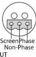
Fig 3-4: RB-DA6P Phoenix Connectors
Input Gain Control
The input gain on the RB-DA6 can be varied -8dB to 18db by adjusting the pre-set potentiometers. These are accessible through the holes in the front panel. The RB-DA6 has separate left and right master gain controls.
Stereo/Mono Operation
The mode of operation may be switched between a stereo distributed channel to 6 stereo channels, and a mono channel to 12 mono channels, by the push button on the front panel, which is recessed to prevent accidental switching.
Technical Specifications RB-DA6P
Audio Specifications
Input Impedance: >20kΩ bridging
Output Impedance: <50Ω
Maximum Input Level: +28dBu
Maximum Output Level: +28dBu
Frequency Response: 20Hz to 20kHz ± 0.1dB (600Ω load, ref 1kHz)
Gain Range: Adjustable 8dB loss to 18dB gain
Common Mode Rejection:>66dB typically
Distortion: 0.01% THD @ 1kHz, ref +8dBu output
Noise: -100dB unity gain ref +8dB (RB-DA6)
Connections
Inputs: 2 x Phoenix 3 pin female (Balanced, can be unbalanced)
Outputs: 12 x Phoenix 3 pin male (Balanced, can be unbalanced)
Mains Input: Filtered IEC, 110V-120V, or 220-240V, fused, 6W maximum
Fuse Rating: Anti-surge fuse 100mA 20 x 5mm (230VAC) Anti-surge fuse 250mA 20 x 5mm (115VAC)
Equipment Type
RB-DA6P:

6 way stereo distribution amplifier with Phoenix connectors
Physical Specifications
Dimensions (Raw): 48cm (W) x 10.8cm (D) x 4.2cm (H) (1U) 19" (W) x 4.3" (D) x 1.7" (H) (1U)
Dimensions (Boxed): 58.5cm (W) x 22.5cm (D) x 7cm (H) 21" (W) x 8" (D) x 2.4" (H)
Weight:
Nett: 1.3kg Gross: 1.9kg
Nett: 2.9lbs Gross: 4.2lbs
4 Audio Distribution Amplifier - RB-DA6R
4 RB-DA6R 6 Way Stereo Distribution Amplifier With RJ45 Outputs
Introduction

Fig 4-1: RB-DA6R Front Panel
The RB-DA6R is a high performance 6 way stereo analogue distribution amplifiers for splitting a source to a number of different outputs. The RB-DA6R has 1 stereo input and 6 stereo outputs with gain control on both inputs. It can also be configured so that 1 mono input is distributed to 12 outputs.
A rear panel mounted switch selects between electronically balanced inputs via either XLR-3 or RJ45 connectors, or unbalanced inputs via RCA Phono connectors. The balanced inputs can be wired unbalanced. The electronically balanced outputs are via RJ45 connectors and can also be wired unbalanced.
The RJ45 connectors are wired to be StudioHub compatible, a format defined by Radio Systems Inc.
The RB-DA6R has master left and right gain controls which are pre-set potentiometers accessible through the front panel, providing a gain range of -8dB to +18dB. An LED power indicator on the front panel shows the unit is powered.
System Block Diagram
![graph LR A["Balanced Inputs"] --> B["Input Select"] C["XLR-3"] --> B D["Right"] --> B E["RJ-45"] --> B F["Left & Right"] --> B G["Unbalanced Inputs"] --> B H["Left"] --> I["Output"] J["RCA Phono"] --> I K["Right"] --> I B --> L["Stereo/Mono"] B --> M["Gain"] B --> N["Gain"] style B fill:#f9f,stroke:…](/content/2026/05/1083478/images/e4138c75484314a8a87a34a9dd9552f079aa1c500d8a7d773867cbcf9d4c99e1.jpg)
Fig 4-2: RB-DA6R System Block Diagram
Connections and Operation

Fig 4-3: RB-DA6R Rear Panel
Balanced Inputs
Balanced professional inputs are provided via dual XLR-3 connectors or the single RJ45 connector. The two connector types are wired in parallel and each can take unbalanced signals by connecting the non-phase of each channel to signal ground (screen). The inputs can be configured as either stereo, with six stereo outputs, or as mono with twelve outputs.

Fig 4-4: RB-DA6R Input Selector Switch
The XLR-3 pin inputs have the following connections:
Pin 1: Screen
Pin 2: Phase
Pin 3: Non-Phase
4 Audio Distribution Amplifier - RB-DA6R
The RJ45 Input is wired according to the StudioHub+ standard and has the following connections:
Pin 1: Left Phase
Pin 2: Left Non-Phase
Pin 3: Right Phase
Pin 4: Screen
Pin 5: No Connection
Pin 6: Right Non-Phase
Pin 7: No Connection
Pin 8: No Connection
Unbalanced Inputs
The RCA Phono input connectors provide an unbalanced input with an additional gain of +10dB to compensate for consumer level signals.
Input Selector Switch
This switch controls which input is routed to the outputs; either balanced (XLR-3 or RJ45) or unbalanced (RCA Phono).
Stereo Outputs 1-6 (Mono Outputs 1-12)
The electronically balanced outputs, which can be wired unbalanced, are via six RJ45 connectors. Each output is individually buffered so that a short on one output will not affect the others. They are wired according to the StudioHub+ standard and have the following connections:
Pin 1: Left Phase
Pin 2: Left Non-Phase
Pin 3: Right Phase
Pin 4: Screen
Pin 5: No Connection
Pin 6: Right Non-Phase
Pin 7: No Connection
Pin 8: No Connection
Input Gain Control
The input gain on the RB-DA6R can be varied -8dB to +18dB by adjusting the pre-set potentiometers. These are accessible through the holes in the front panel. The RB-DA6R has separate left and right master gain controls.

Fig 4-5: RB-DA6R Front Panel Input Gain Controls and Stereo/Mono Switch
Stereo/Mono Operation
The mode of operation may be switched between a stereo distributed channel to 6 stereo channels, and a mono channel to 12 mono channels, by the push button on the front panel, which is recessed to prevent accidental switching. In mono mode the left input channel is distributed to all outputs.
Technical Specification RB-DA6R
Audio Specifications
Input Impedance (XLR): >20kΩ balanced bridging
Input Impedance (RCA): >20kΩ unbalanced
Output Impedance: <50Ω
Maximum Input Level: +28dBu
Maximum Output Level: +28dBu
Frequency Response: 20Hz to 20kHz ± 0.1dB (600R load, ref 1kHz)
Gain Range: Adjustable 8dB loss to 18dB gain
Common Mode Rejection:>66dB typically
Distortion: 0.01% THD @ 1kHz, ref +8dBu output
Noise: -98dB unity gain ref +8dB (RB-DA6R)
-86dB unity gain ref +8dB (RB-DA6RG)
Connections
Inputs: 2 x XLR-3 pin female (Balanced, can be unbalanced)
1 x RJ45 socket (Balanced, can be unbalanced)
2 x RCA Phono sockets (Unbalanced)
Outputs: 6 x RJ45 socket (Balanced, can be unbalanced)
Mains Input: Filtered IEC, 110V-120V, or 220V-240V, fused, 6W max
Fuse Rating: Anti-surge fuse 100mA 20 x 5mm (230VAC) Anti-surge fuse 200mA 20 x 5mm (115VAC)
Equipment Type
RB-DA6R:
with RJ45 ol

6 way stereo distribution amplifier
Physical Specifications
Dimensions (Raw): 48cm (W) x 10.8cm (D) x 4.2cm (H) (1U) 19" (W) x 4.3" (D) x 1.7" (H) (1U)
Dimensions (Boxed): 53cm (W) x 20.5cm (D) x 6cm (H) 21" (W) x 8" (D) x 2.4" (H)
Weight: Nett: 1.3kg Gross: 1.9kg
Nett: 2.9lbs Gross: 4.2lbs
5 Audio Distribution Amplifier - RB-DA6RG
5 RB-DA6RG 6 Way Stereo Distribution Amplifier With RJ45 Outputs
Introduction
Mono/Stereo SwitchOutput Gain Control

Fig 5-1: RB-DA6RG Front Panel
The RB-DA6RG is a high performance 6 way stereo analogue distribution amplifiers for splitting a source to a number of different outputs. The RB-DA6R has 1 stereo input and 6 stereo outputs with individual gain control on every output. It can also be configured so that 1 mono input is distributed to 12 outputs.
A rear panel mounted switch selects between electronically balanced inputs via either XLR-3 or RJ45 connectors, or unbalanced inputs via RCA Phono connectors. The balanced inputs can be wired unbalanced. The electronically balanced outputs are via RJ45 connectors and can also be wired unbalanced.
The RJ45 connectors are wired to be StudioHub compatible, a format defined by Radio Systems Inc.
On the RB-DA6RG each channel has an individual output gain control (normalising) which are all pre-set potentiometers, also accessible through the front panel. These can similarly be adjusted between -8db and +18dB. An extra 10dB of gain is applied to the unbalanced inputs to compensate for lower level consumer signals. The 1-12 mono, 1-6 stereo switch is recessed on the front panel to prevent accidental knocking. An LED power indicator on the front panel shows the unit is powered.
System Block Diagram
![graph LR A["Balanced Inputs"] --> B["XLR-3"] A --> C["RJ-45"] A --> D["Unbalanced Inputs"] E["Left"] --> B F["Right"] --> C G["Left & Right"] --> C H["RCA Phono"] --> I["Output"] J["Input Select"] --> B K["Stereo/Mono"] --> L["Gain Gain Gain Gain Gain Gain Gain Gain Gain Gain Gain Gain Gain Gain Gai…](/content/2026/05/1083478/images/5c768ce683fc56f2ed8ad3d531347ad79a4b987dfca0a8513b9cdd284ff73b98.jpg)
Fig 5-2: RB-DA6RG System Block Diagram
Connections and Operation

Fig 5-3: RB-DA6RG Rear Panel
5 Audio Distribution Amplifier - RB-DA6RG
Balanced Inputs
Balanced professional inputs are provided via dual XLR-3 connectors or the single RJ45 connector. The two connector types are wired in parallel and each can take unbalanced signals by connecting the non-phase of each channel to signal ground (screen). The inputs can be configured as either stereo, with six stereo outputs, or as mono with twelve outputs.
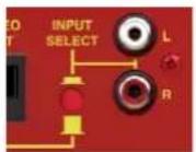
Fig 5-4: RB-DA6RG
Input Selector Switch
The XLR-3 pin inputs have the following connections:
Pin 1: Screen
Pin 2: Phase
Pin 3: Non-Phase
The RJ45 input is wired according to the StudioHub+ standard and has the following connections:
Pin 1: Left Phase
Pin 2: Left Non-Phase
Pin 3: Right Phase
Pin 4: Screen
Pin 5: No Connection
Pin 6: Right Non-Phase
Pin 7: No Connection
Pin 8: No Connection
Unbalanced Inputs
The RCA Phono input connectors provide an unbalanced input with an additional gain of +10dB to compensate for consumer level signals.
Input Selector Switch
This switch controls which input is routed to the outputs; either balanced (XLR-3 or RJ45) or unbalanced (RCA Phono).
Stereo Outputs 1-6 (Mono Outputs 1-12)
The electronically balanced outputs, which can be wired unbalanced, are via six RJ45 connectors. Each output is individually buffered so that a short on one output will not affect the others. They are wired according to the StudioHub+ standard and have the following connections:
Pin 1: Left Phase
Pin 2: Left Non-Phase
Pin 3: Right Phase
Pin 4: Screen
Pin 5: No Connection
Pin 6: Right Non-Phase
Pin 7: No Connection
Pin 8: No Connection
Output Gain Control
The output gain on the RB-DA6RG can be varied -8dB to +18dB by adjusting the pre-set potentiometers. These are accessible through the holes in the front panel. The RB-DA6RG has output gain controls on every output.

Fig 5-5: RB-DA6RG Front Panel Output Gain Controls and Stereo/Mono Switch
Stereo/Mono Operation
The mode of operation may be switched between a stereo distributed channel to 6 stereo channels, and a mono channel to 12 mono channels, by the push button on the front panel, which is recessed to prevent accidental switching. In mono mode the left input channel is distributed to all outputs.
Technical Specification RB-DA6RG
Audio Specifications
Input Impedance (XLR): >20kΩ balanced bridging
Input Impedance (RCA): >20kΩ unbalanced
Output Impedance: <50Ω
Maximum Input Level: +28dBu
Maximum Output Level: +28dBu
Frequency Response: 20Hz to 20kHz ± 0.1dB (600R load, ref 1kHz)
Gain Range: Adjustable 8dB loss to 18dB gain
Common Mode Rejection:>66dB typically
Distortion: 0.01% THD @ 1kHz, ref +8dBu output
Noise: -98dB unity gain ref +8dB (RB-DA6R)
-86dB unity gain ref +8dB (RB-DA6RG)
Connections
Inputs: 2 x XLR-3 pin female (Balanced, can be unbalanced)
1 x RJ45 socket (Balanced, can be unbalanced)
2 x RCA Phono sockets (Unbalanced)
Outputs: 6 x RJ45 socket (Balanced, can be unbalanced)
Mains Input: Filtered IEC, 110V-120V, or 220V-240V, fused, 6W max
Fuse Rating: Anti-surge fuse 100mA 20 x 5mm (230VAC)
Anti-surge fuse 200mA 20 x 5mm (115VAC)
Equipment Type
RB-DA6RG: 6 way stereo distribution amplifier with RJ45 outputs and output gain
Physical Specifications
Dimensions (Raw): 48cm (W) x 10.8cm (D) x 4.2cm (H) (1U) 19" (W) x 4.3" (D) x 1.7" (H) (1U)
Dimensions (Boxed): 53cm (W) x 20.5cm (D) x 6cm (H) 21" (W) x 8" (D) x 2.4" (H)
Weight: Nett: 1.3kg Gross: 1.9kg
Nett: 2.9lbs Gross: 4.2lbs
6 Audio Distribution Amplifier - RB-DA4x5
6 RB-DA4x5 4 Input, 4 x 5 Output Distribution Amplifier/Mixer

Fig 6-1: RB-DA4x5 Front Panel
The RB-DA4x5 is a 1U rack-mount combined distribution amplifier and mixer. It has 4 mono analogue audio inputs on female XLR and 4 groups of 5 outputs on 15 way D-type connectors. Each output group has a five way front-panel DIP switch assigned to it which is used to select the input(s) to send to the output group. This enables each of the four inputs, and a 1kHz 0dBu tone, to be mixed to the output group.
The inputs and outputs are electronically balanced and can be wired unbalanced. Each input has adjustable gain using a preset potentiometer, providing a gain range of -8dB to +18dB. Each output is individually buffered so that a short circuit on one output will not affect the others. The output gain of each group can similarly be adjusted between -8dB and +18dB using preset potentiometers.
The DIP switch settings and gain controls are recessed beneath a front-mounting screw-on cover so that settings can not be accidentally altered, for secure applications. Four bright front-panel signal present LEDs show the levels of either the inputs or the output groups by pressing the AUDIO PRESENCE button. The LEDs will show green illumination from -12dBu through to 0dBu, amber from 0dBu through to +6dBu and red for inputs and outputs at +6dBu and over.
System Block Diagram
![graph TD A["Balanced XLR Input 1"] --> B["Gain"] C["Balanced XLR Input 2"] --> D["Gain"] E["Balanced XLR Input 3"] --> F["Gain"] G["Balanced XLR Input 4"] --> H["Gain"] I["Reference Tone"] --> J["Gain"] K["Output 1 Switch Bank Gain"] --> L["Meter 1 Output"] M["Output 1 Switch Bank Gain"] --> N["Mete…](/content/2026/05/1083478/images/5453f5295aef275c062f5f437d0ae459e9a7c296c9a4a1531fd7e6267eef208c.jpg)
Fig 6-2: RB-DA4x5 System Block Diagram
Rear Panel Connections and Operation

Fig 6-3: RB-DA4x5 Rear Panel
6 Audio Distribution Amplifier - RB-DA4x5
Audio Inputs 1-4
The XLR 3 pin sockets used for the audio inputs are electronically balanced and have an impedance of 20kΩ bridging. They are routed to the switch matrix. Each XLR has the following connections:
Pin 1: Screen
Pin 2: Phase
Pin 3: Non-phase
D-Type Audio Output Groups 1-4
Each output group connector has 5xDA driven balanced audio outputs on a D-type connector outputs each with an output impedance of <50Ω .
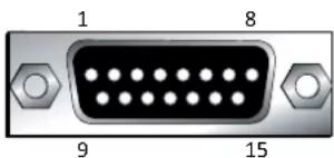

Output 1 Output 3 Output 5
Fig 6-4: RB-DA4x5 Audio Output Group15-Way D-Type Plug
Function Output 1 Output 2 Output 3 Output 4 Output 5
Out - Pin No. 13467
Out + Pin No. 9 10 12 13 15
Signal Ground
2 11 5 14 8
Pin No.
Fig 6-5: RB-DA4x5 Pinout for Audio Output Group Connector
Monitor LEDs
There are 4 LEDs on the front panel that indicate the relative levels of the audio signals at the inputs or outputs. A pushbutton switch on the front panel toggles the function of these LEDs between input and output. These LEDs indicate the levels of the signals by illuminating green for signals between -12 and 0dBu, illuminating yellow for signals between 0 and +6dBu, and illuminating red for signals over +6dBu.
Input Level Adjustment
The gain for each input can be adjusted through pre-set potentiometers that are accessible from behind the removable plate on the front panel. The gain of each balanced input is variable within a range of -8dB to +18dB into the router input.
Output Level Adjustment
The gain for each output group can be adjusted through pre-set potentiometers that are accessible from behind the removable plate on the front panel. The gain of each output group is variable within a range of -8dB to +18dB from the router output.
Routing Selection
Each output group is capable of selecting its signal from any combination of inputs and the test tone. Set the appropriate dip-switch for that group & that input to the on position to include the signal in the group's output.

On ↓

Fig 6-6: RB-DA4x5 Routing Selection Switch
| Function | Group 1Routing | Group 2Routing | Group 3Routing | Group 4Routing |
| Input 1 SW1-1 On SW1-6 On SW2-1 On SW2-6 On | ||||
| Input 2 SW1-2 On SW1-7 On SW2-2 On SW2-7 On | ||||
| Input 3 SW1-3 On SW1-8 On SW2-3 On SW2-8 On | ||||
| Input 4 SW1-4 On SW1-9 On SW2-4 On SW2-9 On | ||||
| Test Tone SW1-5 On SW1-10 On SW2-5 On SW2-10 On | ||||
Fig 6-7: RB-DA4x5 Routing Selection Switch Functions
Alignment Test Tone
Each of the output groups has the capability of selecting a 1kHz, 0dBu test tone. This signal can be used as a reference to set the output gain levels. Once these values are known then the input gains can be set by providing a known tone to the input and adjusting the input gain to the required level. It is possible to use this test tone as a reference level for the input gain by adjusting the output gains to unity and then looping back any output to the input connector. The on-board oscillator is temperature sensitive and in cold conditions may take a short time to start oscillating. In any case you should always allow the unit to fully come to its normal operating temperature before adjusting the gains.
Technical Specifications RB-DA4x5
Audio Specifications
| Maximum Input Level: +28dBu |
| Input Impedance (XLR): >20kΩ balanced bridging |
| Output Impedance: | <50Ω |
| Maximum Output Level: +28dBu |
| Distortion: 0.01% THD @ 1kHz, ref +8dBu output |
| Noise: -100dB, unity gain, ref +8dBu output |
| Common Mode Rejection:>66dB typically |
| Frequency Response: 20Hz to 20kHz ±0.1dB (600Ω load, ref 1kHz) |
| Input Gain Range: Adjustable 8dB loss to 18dB gain (channel 1-4 adjust) |
| Output Gain Range: Adjustable 8dB loss to 18dB gain (group 1-4 adjust) |
Connections
| Inputs (4 x Mono): 4 x XLR 3 pin female (Balanced) |
| Outputs (20 x Mono): 4 x 15 way D-type (Balanced) |
| Mains Input: Filtered IEC, 110V-120V, or 220-240V switchable, fused, 9W maximum |
| Fuse Rating: | Anti-surge fuse 100mA 20 x 5mm (230VAC) |
| Anti-surge fuse 250mA 20 x 5mm (115VAC) | |
Equipment Type
| RB-DA4x5: & mixer | RK3 | 4 input to 20 output distribution amplifier |
Physical Specifications
| Dimensions (Raw): | 48cm (W) x 15.8cm (D*) x 4.2cm (H) (1U) |
| 19" (W) x 6.2" (D*) x 1.7 (H) (1U) | |
| Dimensions (Boxed): | 59cm (W) x 27.4cm (D*) x 10.8cm (H) |
| 23.2" (W) x 10.8" (D*) x 4.3" (H) | |
| Weight: | Nett: 1.6kg | Gross: 2.2kg |
| Nett: 3.5lbs | Gross: 4.8lbs |
* Note that this product is deeper than standard Redboxes.
7 Audio Distribution Amplifier - RB-DA24MD
7 RB-DA24MD 24 Way Mono Audio Distribution Amplifier
Introduction

Fig 7-1: RB-DA24MD Front Panel
The RB-DA24MD is a 1U rack mount high performance 24 way audio distribution amplifier. It has 2 inputs which can be each individually routed to 12 outputs, or mixed and routed to all 24 outputs.
The XLR Inputs and D-type outputs are electronically balanced and can be wired unbalanced. Each output is individually buffered so that a short circuit on one won't affect the others. Each output is also protected against connection to both POE (power over Ethernet) and phantom power circuits.
The RB-DA24MD has master gain controls for both input 1 and input 2 which are pre-set potentiometers accessible through the rear panel. These controls allow the gain to be adjusted from -15dB to +15dB, useful for normalising consumer to professional signals and vice versa. An LED power indicator on the front panel shows the unit is powered.
A 125Hz 6dB per octave roll off filter is activated by a push switch on the rear panel. When selected the filter is the applied to both inputs.
![graph LR A["Input 1 (L) Balanced"] --> B["Gain LF Filter Mix Level"] C["Input 2 (R) Balanced"] --> D["-0 LF Filter Gain"] B --> E["Dual Mono (Stereo)/Mixed Mono"] D --> F["Dual Mono (Stereo)/Mixed Mono"] E --> G["Outputs 13-24 (R) Balanced"] F --> G G --> H["Outputs 1-12 (L) Balanced"]](/content/2026/05/1083478/images/82ef765c83da19f69d0d2ee226eef4f38d4641d0ca22379c65e04a47f62d1d0f.jpg)
Connections And Operation

Fig 7-3: RB-DA24MD Rear Panel
Inputs (1&2)
The XLR-3 input connectors can take balanced professional levels, or unbalanced consumer levels by connecting the non-phase to the signal ground and adjusting the rear panel input gain controls. The inputs can be configured as either dual mono, input 1 routed to outputs 1-12 and input 2 routed to outputs 13-24, or mixed mono, inputs 1 and 2 mixed at a pre-set level and routed to all 24 outputs. The XLR 3 pin input has the following connections:
Pin 1: Screen
Pin 2: Phase
Pin 3: Non-Phase
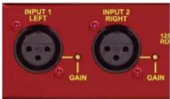
Fig 7-4: Analogue Input
Outputs (1 - 24)
The 25 way D-type outputs are electronically balanced, and can be wired unbalanced (not recommended). Each output is individually buffered so that a short circuit on one output will not affect the others. The outputs are also protected from connection to POE (power over Ethernet) and phantom power circuits. They have the following connections:
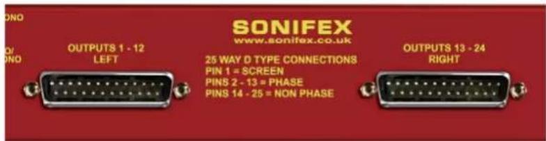
Fig 7-5: 25 Way D-Type Outputs
7 Audio Distribution Amplifier - RB-DA24MD
| Outputs 1-12 D-Type Outputs 13-24 D-Type | ||
| Pin No. Signal | Signal | |
| Pin 1 Screen S | Screen | |
| Pin 2 Output 1 | - Phase Output 13 - Phase | |
| Pin 14 Output | 1 - Non-Phase Output 13 - | Non-Phase |
| Pin 3 Output 2 | - Phase Output 14 - Phase | |
| Pin 15 Output | 2 - Non-Phase Output 14 - | Non-Phase |
| Pin 4 Output 3 | - Phase Output 15 - Phase | |
| Pin 16 Output | 3 - Non-Phase Output 15 - | Non-Phase |
| Pin 5 Output 4 | - Phase Output 16 - Phase | |
| Pin 17 Output | 4 - Non-Phase Output 16 - | Non-Phase |
| Pin 6 Output 5 | - Phase Output 17 - Phase | |
| Pin 18 Output | 5 - Non-Phase Output 17 - | Non-Phase |
| Pin 7 Output 6 | - Phase Output 18 - Phase | |
| Pin 19 Output | 6 - Non-Phase Output 18 - | Non-Phase |
| Pin 8 Output 7 | - Phase Output 19 - Phase | |
| Pin 20 Output | 7 - Non-Phase Output 19 - | Non-Phase |
| Pin 9 Output 8 | - Phase Output 20 - Phase | |
| Pin 21 Output | 8 - Non-Phase Output 20 - | Non-Phase |
| Pin 10 Output | 9 - Phase Output 21 - Phase | |
| Pin 22 Output | 9 - Non-Phase Output 21 - | Non-Phase |
| Pin 11 Output | 10 - Phase Output 22 - Phase | |
| Pin 23 Output | 10 - Non-Phase Output 22 - | Non-Phase |
| Pin 12 Output | 11 - Phase Output 23 - Phase | |
| Pin 24 Output | 11 - Non-Phase Output 23 - | Non-Phase |
| Pin 13 Output | 12 - Phase Output 24 - Phase | |
| Pin 25 Output | 12 - Non-Phase Output 24 - | Non-Phase |
Input Gain Control
The input gain on the RB-DA24MD can be varied between -15dB and +15dB by adjusting the pre-set potentiometers. These are accessible through the holes in the rear panel. The RB-DA24MD has separate input 1 and input 2 gain controls.
LF Roll Off Filter
A low frequency roll off filter is activated by a push switch on the rear panel. This implements a 125Hz 6dB per octave roll off filter which is applied to both inputs.
Dual Mono/Mixed Mono Operation
The method of operation may be switched between stereo/dual mono and mixed mono. When the RB-DA24MD is set to dual mono each input is distributed separately to outputs 1-12 and 13-24. Input 1 is routed to outputs 1-12 and input 2 to 13-24. When it is set to mixed mono mode both inputs are mixed and routed to all 24 outputs.
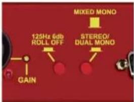
Fig 7-6: 25 Roll Off and Dual Mono/Mixed Operation Switches
Mixed Mono Settings
When set to mixed mono operation there are 3 different mix level modes, selected by the 4 jumpers on the PCB.
| Jumper Link Mix Mode |
| Off (Input 1 + Input 2) -6dB |
| Pin 1 & 2 (Input 1 + Input 2) -3dB |
| Pin 2 & 3 Input 1 + Input 2 |
All jumpers (J1 to J4) must be set the same for correct operation.
Technical Specifications RB-DA24MD
| Audio Specifications: |
| Input Impedance: >20kΩ bridging (balanced) |
| Output Impedance: <50Ω |
| Maximum Input Level: +28dBu |
| Maximum Output Level: +28dBu |
| Frequency Response: 20Hz to 20kHz ±0.1dB (600Ω load, ref 1kHz) |
| Gain Range: Adjustable -15dB loss to +15dB gain |
| Common Mode Rejection: >66dB typically |
| LF Roll Off Filter 125Hz at 6dB/octave |
| Distortion: 0.01%THD @ 1kHz, red + 8dBu output |
| Noise: -100dB unity gain, ref +8dBu output |
Connections:
| Inputs: 2 x XLR 3 pin female (balanced) |
| Outputs: 2 x 25 way D-type plug (balanced, can be unbalanced) |
| Mains Input: Filtered IEC, switchable 110-120V, or 220-240V, fused, 12W maximum |
| Fuse Rating: Anti-surge fuse 100mA x 5mm (230VAC) Anti-surge fuse 200mA x 5mm (115VAC) |
| Equipment Type: | |
| Equipment Type: RB-DA24MD | 24 Way Mono Distribution Amplifier |
| RK3 | |
| Physical Specification: | |
| Dimensions (Raw): | 48cm (W) x 15.8cm (D) x 4.2 (H) (1U)19" (W) x 6.2" (D) x 1.7" (H) (1U) |
| Dimensions (Boxed) | 58.5cm (W) x 27.4cm (D) x 10.8cm (H)23" (W) x 10.9" (D) x 4.3" (H) |
| Weight | Nett: 1.6kg Gross: 2.2kgNett: 3.5lbs Gross: 4.8lbs |
8 Audio Distribution Amplifier - RB-DDA6A
8 RB-DDA6A 6 Way Stereo AES/EBU Digital Distribution Amplifier
Introduction

Fig 8-1: RB-DDA6A Front Panel

The RB-DDA6A digital distribution amplifier is used for distributing digital audio data in AES/EBU format, repeating both the audio data and the status information of the input whilst re-normalising to standard digital audio levels.
It has a single XLR-3 female AES/EBU audio input which is distributed to 6 XLR-3 male AES/EBU outputs.
Applications include distributing audio from a digital mixing desk to multiple digital recorders, or feeding multiple studios with an output from a DAT machine.
It can accept input sample rates in the range of 30kHz - 100kHz, and bit rates of 16, 20 and 24 bit. So, it can be used for standard CD signal distribution at 16 bit 44.1kHz, as well as for high quality 24 bit 96kHz recording.
AES/EBU Input
The XLR 3 pin socket has an impedance of 110Ω. It has the following connections:
Pin 1: Screen
Pin 2: Phase
Pin 3: Non-phase
AES/EBU Outputs
The XLR 3 pin sockets have an impedance of 110Ω. They have the following connections:
Pin 1: Screen
Pin 2: Phase
Pin 3: Non-phase
Rear Panel Connections and Operations
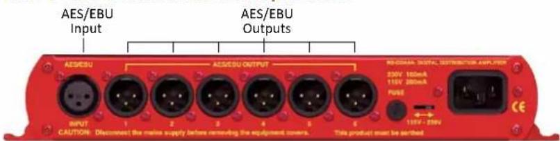
Fig 8-2: RB-DDA6A Rear panel
System Block Diagram
![graph LR A["Input XLR-3 Female"] --> B["AES/EBU Receiver"] B --> C1["AES/EBU Transmitter"] --> D1["Output XLR-3 Male"] B --> C2["AES/EBU Transmitter"] --> E1["Output XLR-3 Male"] B --> C3["AES/EBU Transmitter"] --> F1["Output XLR-3 Male"] B --> C4["AES/EBU Transmitter"] --> G1["Output XLR-3 Male"] B…](/content/2026/05/1083478/images/c133926d690cbe401b81eb0e43fe827e889fa9331aee253fb12f3e3945bee10e.jpg)
Fig 8-3: RB-DDA6A System Block Diagram
8 Audio Distribution Amplifier - RB-DDA6A
Technical Specifications RB-DDA6A
Audio Specifications
Input Impedance: 110Ω ± 20% balanced
Output Impedance: 110Ω ± 20% balanced
Sample Freq Range: 30-100kHz (i.e. including 32kHz, 44.1kHz, 48kHz, 64kHz, 88.2kHz and 96kHz)
Signal Level: 2V/7V peak to peak min/max
Connections
Input: 1 x AES/EBU XLR 3 pin female (balanced)
Outputs: 6 x AES/EBU XLR 3 pin male (balanced)
Mains Input: Filtered IEC, 110-120V, or 220-240V switchable, fused, 6W max
Fuse Rating: Anti-surge fuse 100mA 20 x 5mm (230VAC) Anti-surge fuse 250mA 20 x 5mm (115VAC)
Equipment Type
RB-DDA6A 6.04 AVS/EBU stereo digital distribution amplifier
Physical Specifications
Dimensions (Raw): 28cm (W) x 10.8cm (D) x 4.2cm (H) (1U) 11" (W) x 4.3" (D) x 1.7" (H) (1U)
Dimensions (Boxed): 36cm (W) x 20.5cm (D) x 6cm (H) 14.2" (W) x 8" (D) x 2.4" (H)
Weight: Nett: 0.95kg Gross: 1.4kg Nett: 2.1lbs Gross: 3.2lbs
9 RB-DDA6A-2P 6 Way Stereo AES/EBU Digital Distribution Amplifier With Dual Power Supplies
Introduction
Power Indicator LEDs

Fig 9-1: RB-DDA6A-2P Front Panel
The RB-DDA6A-2P digital distribution amplifier is used for distributing digital audio data in AES/EBU format, repeating both the audio data and the status information of the input whilst re-normalising to standard digital audio levels.
It has a single XLR-3 female AES/EBU audio input which is distributed to 6 XLR-3 male AES/EBU outputs. In the event of power failure to the unit, the input is routed to AES/EBU output 1 by relays to ensure broadcast continuity at all times for output 1.
Applications include distributing audio from a digital mixing desk to multiple digital recorders, or feeding multiple studios with an output from a DAT machine.
It can accept input sample rates in the range of 30kHz - 100kHz, and bit rates of 16, 20 and 24 bit. So, it can be used for standard CD signal distribution at 16 bit 44.1kHz, as well as for high quality 24 bit 96kHz recording.
The unit provides redundancy protection by using two power supply units that can be supplied from separate mains feeds. The unit automatically load shares between the two supplies so that if either supply should fail the unit will continue to work correctly. If both supplies fail the input is connected directly to output 1.
The condition of the two supplies is indicated on the front panel by two red LEDs which illuminate to indicate the correct function of the supply. On the alarm output connector there is a changeover relay to indicate the status of each supply. This is normally closed to indicate power fail and once the supply is working correctly the relay activates to make a normally open contact.
9 Audio Distribution Amplifier - RB-DDA6A-2P
System Block Diagram
![graph TD A["Input"] --> B["Digital Audio Receiver"] B --> C["Power Off Connectivity"] C --> D["Digital Audio Driver"] C --> E["Digital Audio Driver"] C --> F["Digital Audio Driver"] C --> G["Digital Audio Driver"] C --> H["Digital Audio Driver"] C --> I["Digital Audio Driver"] D --> J["PSU 1"] E -->…](/content/2026/05/1083478/images/def17428a86d50ded56535aab7a1ed70ed2c6c6c441803e3c263025d25458208.jpg)
Fig 9-2: RB-DDA6A-2P System Block Diagram
Rear Panel Connections and Operations

Fig 9-3: RB-DDA6A-2P Rear panel
AES/EBU Input
The XLR 3 pin socket has an impedance of 110Ω. It has the following connections:
Pin 1: Screen
Pin 2: Phase
Pin 3: Non-phase
AES/EBU Outputs
The XLR 3 pin sockets have an impedance of 110Ω. They have the following connections:
Pin 1: Screen
Pin 2: Phase
Pin 3: Non-phase
Alarm Connector
Pin 1: Power Supply 1 Common
Pin 2: Power Supply 1 Normally Open
Pin 3: Ground
Pin 4: Power Supply 2 Common
Pin 5: Power Supply 2 Normally Open
Pin 6: Power Supply 1 Normally Closed (indicates supply inactive)
Pin 7: Ground
Pin 8: Ground
Pin 9: Power Supply 2 Normally Closed (indicates supply inactive)
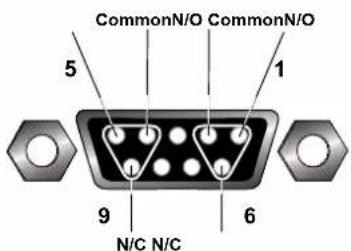
PSU 2PSU 1
Fig 9-4: RB-DDA6A-2P Alarm Connector Diagram
9 Audio Distribution Amplifier - RB-DDA6A-2P
Technical Specification RB-DDA6A-2P
Audio Specifications
Input Impedance: 110Ω ± 20% balanced
Output Impedance: 110Ω ± 20% balanced
Sample Freq Range: 30-100kHz (i.e. including 32kHz, 44.1kHz, 48kHz, 64kHz, 88.2kHz and 96kHz)
Signal Level: 2V/7V peak to peak min/max
Connections
Audio Input: 1 x AES/EBU XLR 3 pin female (balanced)
Audio Outputs: 6 x AES/EBU XLR 3 pin male (balanced)
Alarm Outputs: 2 x Relay output indicators on 1 x 9 pin D-Type socket
Mains Inputs: 2 x Filtered IEC, 85-264V switchable, fused, 6W max
Fuse Ratings: 2 x Anti-surge fuse 1A 20 x 5mm
Equipment Type
RB-DDA6A-2P: 6 way AES/EBU stereo digital distribution amplifier with dual power supplies
Physical Specifications
Dimensions (Raw): 48cm (W) x 10.8cm (D) x 4.2cm (H) (1U) 19" (W) x 4.3" (D) x 1.7" (H) (1U)
Dimensions (Boxed): 58.5cm (W) x 22.5cm (D) x 7cm (H) 23" (W) x 8.9" (D) x 2.8" (H)
Weight: Nett: 1.5kg Gross: 2.0kg Nett: 3.3lbs Gross: 4.4lbs
10 RB-DDA6A3 6 Way Stereo AES-3id Digital Audio Distribution Amplifier
Introduction

Fig 10-1: RB-DDA6A3 Front Panel
The RB-DDA6A3 digital distribution amplifier is used for distributing digital audio data in AES-3id format, repeating both the audio data and the status information of the input whilst re-normalising to standard AES-3id digital audio levels.
It has a single female BNC AES-3id audio input which is distributed to 6 female BNC AES-3id outputs.
It can accept input sample rates in the range of 30kHz - 100kHz, and bit rates of 16, 20 and 24 bit.
AES-3id Input
The AES-3id input has an impedance of 75Ω.
AES-3id Outputs
The AES-3id outputs have an impedance of 75Ω.
Rear Panel Connections and Operations

Fig 10-2: RB-DDA6A3 Rear panel
10 Audio Distribution Amplifier - RB-DDA6A3
System Block Diagram
![graph LR A["Input BNC"] --> B["AES-3id Receiver"] B --> C1["AES-3id Transmitter"] B --> C2["AES-3id Transmitter"] B --> C3["AES-3id Transmitter"] B --> C4["AES-3id Transmitter"] B --> C5["AES-3id Transmitter"] C1 --> D1["Output BNC"] C2 --> D2["Output BNC"] C3 --> D3["Output BNC"] C4 --> D4["Output…](/content/2026/05/1083478/images/cac956e7dec43daa8a191dc3d3f903c26055d805f41cbb11def947c75385b503.jpg)
Fig 10-3: RB-DDA6A3 System Block Diagram
Technical Specifications RB-DDA6A3
Audio Specifications
Input Impedance: 75Ω
Output Impedance: 75Ω
Sample Freq Range: 30-100kHz (i.e. including 32kHz, 44.1kHz, 48kHz, 64kHz, 88.2kHz and 96kHz)
Signal Level: 0.8V/1.2V peak to peak min/max
Connections
Input: 1 x BNC female
Outputs: 6 x BNC female
Mains Input: Filtered IEC, 110-120V, or 220-240V switchable, fused, 6W max
Fuse Rating: Anti-surge fuse 100mA 20 x 5mm (230VAC) Anti-surge fuse 250mA 20 x 5mm (115VAC)
Equipment Type
RB-DDA6A3 6R1A5S2d stereo digital distribution amplifier
Physical Specifications
Dimensions (Raw): 28cm (W) x 10.8cm (D) x 4.2cm (H) (1U) 11" (W) x 4.3" (D) x 1.7" (H) (1U)
Dimensions (Boxed): 36cm (W) x 20.5cm (D) x 6cm (H) 14.2" (W) x 8" (D) x 2.4" (H)
Weight: Nett: 0.92kg Gross: 1.46kg Nett: 2.1lbs Gross: 3.2lbs
11 Audio Distribution Amplifier - RB-DDA6S
11 RB-DDA6S 6 Way Stereo S/PDIF Digital Distribution Amplifier
Introduction

Fig 11-1: RB-DDA6S Front Panel

The RB-DDA6S digital distribution amplifier is similar to the above models except that it is used for distributing digital audio data in S/PDIF format.
It has a single S/PDIF audio input which is distributed to 6 x S/PDIF audio outputs at the same level and condition as the input signal. It can accept input sample rates in the range of 30kHz - 100kHz, and bit rates of 16, 20 and 24 bit.
Uses include audio distribution at 16 bit 44.1kHz from a consumer CD player to multiple digital recorders, distribution of high quality 24 bit 96kHz signals from digital mixing desks to recorders and connection of the output of, say, a DVD player to multiple studios.
S/PDIF Input
The S/PDIF phono input has an impedance of 75Ω.
S/PDIF Outputs
The S/PDIF phono outputs have an impedance of 75Ω.
Rear Panel Connections and Operations

Fig 11-2: RB-DDA6S Rear panel
System Block Diagram
![graph LR A["Input RCA Phono"] --> B["S/PDIF Receiver"] B --> C1["S/PDIF Transmitter"] --> D1["Output RCA Phono"] B --> C2["S/PDIF Transmitter"] --> D2["Output RCA Phono"] B --> C3["S/PDIF Transmitter"] --> D3["Output RCA Phono"] B --> C4["S/PDIF Transmitter"] --> D4["Output RCA Phono"] B --> C5["S/P…](/content/2026/05/1083478/images/c950e91f90ea12d23ac8697f8b73cdad86e82814a01ee049761a115952ca26d1.jpg)
Fig 11-3: RB-DDA6S System Block Diagram
11 Audio Distribution Amplifier - RB-DDA6S
Technical Specifications RB-DDA6S
Audio Specifications
Input Impedance: 75Ω ±5% unbalanced
Output Impedance: 75Ω ±5% unbalanced
Sample Freq Range: 30-100kHz (i.e. including 32kHz, 44.1kHz, 48kHz, 64kHz, 88.2kHz and 96kHz)
Signal Level: Balanced min 0.5V ±20% peak to peak
Connections
Input (unbalanced): 1 x S/PDIF RCA phono female
Outputs: 6 x S/PDIF RCA phono female (unbalanced)
Mains Input: Filtered IEC, 110-120V, or 220-240V switchable, fused, 6W max
Fuse Rating: Anti-surge fuse 100mA 20 x 5mm (230VAC) Anti-surge fuse 250mA 20 x 5mm (115VAC)
Equipment Type
RB-DDA6S RKF1 stereo S/PDIF digital distribution amplifier
Physical Specifications
Dimensions (Raw): 28cm (W) x 10.8cm (D) x 4.2cm (H) (1U) 11" (W) x 4.3" (D) x 1.7" (H) (1U)
Dimensions (Boxed): 36cm (W) x 20.5cm (D) x 6cm (H) 14.2" (W) x 8" (D) x 2.4" (H)
Weight RB-DDA6S: Nett: 0.9kg Gross: 1.35kg Nett: 2lbs Gross: 3lbs
12 RB-DDA6W 6 Way Word Clock Distribution Amplifier
Introduction

Fig 12-1: RB-DDA6W Front Panel
The RB-DDA6W 6 Way Word Clock Distribution Amplifier distributes a word clock BNC input signal to 6 word clock BNC outputs re-conditioned. It is used in distributing reference clocks for digital audio systems.
It has a single female BNC input which is distributed to 6 female BNC outputs.
The unit's primary application is to distribute a master TTL word clock source to multiple pieces of equipment that need to be synchronised from the master.
Rear Panel Connections and Operations
Word Clock Input Word Clock Outputs

Fig 12-2: RB-DDA6W Rear Panel
Word Clock Input
The Word Clock BNC input has an impedance of 75 Ω.
Word Clock Outputs
The Word Clock BNC outputs have an impedance of <75\ Ω .
12 Audio Distribution Amplifier - RB-DDA6W
System Block Diagram
![graph LR A["Input BNC"] --> B["TTL Receiver"] B --> C1["TTL Transmitter"] B --> C2["TTL Transmitter"] B --> C3["TTL Transmitter"] B --> C4["TTL Transmitter"] B --> C5["TTL Transmitter"] C1 --> D1["Output BNC"] C2 --> D2["Output BNC"] C3 --> D3["Output BNC"] C4 --> D4["Output BNC"] C5 --> D5["Output…](/content/2026/05/1083478/images/559ba358ace15743ddd07e599ad5364740301fa76b832f41a84ec07be5fca8a6.jpg)
Fig 12-3: RB-DDA6W System Block Diagram
Technical Specifications RB-DDA6W
Signal Specifications
Input Impedance : 75Ω
Output Impedance: <75Ω
Connections
Input: 1 x BNC female
Outputs: 6 x BNC female
Mains Input: Filtered IEC, 110-120V, or 220-240V
switchable, fused, 6W max
Fuse Rating: Anti-surge fuse 100mA 20 x 5mm (230VAC)
Anti-surge fuse 250mA 20 x 5mm (115VAC)
Equipment Type
RB-DDA6W: 8001 word clock distribution amplifier
Physical Specifications
Dimensions (Raw): 28cm (W) x 10.8cm (D) x 4.2cm (H) (1U)
13 RB-DDA6W-2P 6 Way Word Clock Distribution Amplifier With Dual Power Supplies
Introduction
Power Indicator LEDs

Fig 13-1: RB-DDA6W-2P Front Panel
The RB-DDA6W-2P word clock distribution amplifier distributes a word clock BNC input signal to 6 word clock BNC outputs re-conditioned. It is used to distribute reference clocks for digital audio systems.
It has a single female BNC audio input which is distributed to 6 female BNC outputs. The units primary application is to distribute a master TTL word clock source to multiple pieces of equipment that need to be synchronised from the master.
The unit provides redundancy protection by using two power supply units that can be supplied from separate mains feeds. The unit automatically load shares between the two supplies so that if either supply should fail the unit will continue to work correctly. If both supplies fail the input is connected directly to output 1.
The condition of the two supplies is indicated on the front panel by two red LEDs which illuminate to indicate the correct function of the supply. On the alarm output connector there is a changeover relay to indicate the status of each supply. This is normally closed to indicate power fail and once the supply is working correctly the relay activates to make a normally open contact.
System Block Diagram
![graph LR A["Input BNC"] --> B["TTL Receiver"] B --> C["TTL Transmitter"] B --> D["TTL Transmitter"] B --> E["TTL Transmitter"] B --> F["TTL Transmitter"] B --> G["TTL Transmitter"] C --> H["Output BNC"] D --> I["Output BNC"] E --> J["Output BNC"] F --> K["Output BNC"] G --> L["Output BNC"] H --> M["…](/content/2026/05/1083478/images/d736f7c2e88a394c63fe4ff4b058da441cc8bb4c3ade9e7a9802b97608b3e719.jpg)
Fig 13-2: RB-DDA6W-2P System Block Diagram
13 Audio Distribution Amplifier - RB-DDA6W-2P
Rear Panel Connections and Operations

Fig 13-3: RB-DDA6W-2P Rear Panel
Word Clock Input
The Word Clock BNC input has an impedance of 75Ω.
Word Clock Outputs
The Word Clock BNC outputs have an impedance of <75 Ω.
Alarm Connector
Pin 1: Power Supply 1 Common
Pin 2: Power Supply 1 Normally Open
Pin 3: Ground
Pin 4: Power Supply 2 Common
Pin 5: Power Supply 2 Normally Open
Pin 6: Power Supply 1 Normally Closed (indicates supply inactive)
Pin 7: Ground
Pin 8: Ground
Pin 9: Power Supply 2 Normally Closed (indicates supply inactive)

PSU 2PSU 1
Fig 13-4: RB-DDA6W-2P Alarm Connector Diagram
Technical Specification For RB-DDA6W-2P
Audio Specification
Input impedance: 75Ω
Output impedance: <75Ω
Connections
Audio Inputs: 1 x BNC female
Audio Outputs: 6 x BNC female
Alarm Outputs: 2 x Relay output indicators on 1 x 9 pin D-Type socket
Mains Input: 2 x Filtered IEC, 85-264V switchable, fused, 6W max
Fuse Rating: 2 x Anti-surge fuse 1A 20 x 5mm
Equipment Type
RB-DDA6W-2P: 600-word clock distribution amplifier with dual power supplies
Physical Specification
Dimensions (Raw): 48cm (W) x 10.8cm (D) x 4.2cm (H) (1U) 19" (W) x 4.3" (D) x 1.7" (H) (1U)
Dimensions (Boxed): 58.5cm (W) x 22.5cm (D) x 7cm (H) 23" (W) x 8.9" (D) x 2.8" (H)
Weight: Nett: 1.5kg Gross: 2.0kg
Nett: 3.3lbs Gross: 4.4lbs
14 Audio Distribution Amplifier - RB-DDA22
14 RB-DDA22 Digital Audio Distribution Amplifier With Multiple Outputs
Introduction

Fig 14-1: RB-DDA22 Front Panel
The RB-DDA22 digital distribution amplifier is used for distributing digital audio data in many formats, repeating both the audio data and the status information of the input whilst re-clocking the data and re-normalising to the appropriate standard digital audio levels.
The unit has 5 inputs and you can select one of them to distribute to all of the 22 outputs.
Input Signals:
• 1 x XLR 3 female AES/EBU digital audio input
• 1 x BNC AES-3id digital audio input
• 1 x RJ45 AES/EBU digital audio input
• 1 x RCA Phono S/PDIF input
• 1 x TOSLink digital audio optical input
Output Signals:
- 6 x XLR-3 male AES/EBU digital audio outputs
- 6 x BNC AES-3id digital audio outputs
- 6 x RJ45 AES/EBU digital audio outputs
• 2 x RCA Phono S/PDIF outputs
• 2 x TOSLink optical outputs
The RJ-45 connectors are wired to be StudioHub+ compatible, a format defined by Radio Systems Inc.
StudioHub+TM is a registered trademark of Radio Systems Inc
Applications include distributing audio from a digital mixing desk to multiple digital recorders, or feeding multiple studios with an output from a USB audio player.
It can accept input sample rates in the range of 30kHz - 200kHz, and bit rates of 16, 20 and 24 bit. So, it can be used for standard CD signal distribution at 16 bit 44.1kHz, as well as for high quality 24 bit 96kHz or 192kHz recording.

Fig 14-2: RB-DDA22 Front Panel Controls
The front panel has an INPUT SELECT button and 7 indicator LEDs. The button is used to select the input to be used and shows the mode of operation of the unit. The LEDs will indicate, depending on the mode of operation, the input selected,
valid signal presence, or the operational frequency.
Operating Mode
In 'operating mode', the central button LED is unlit. The unit selects this mode when a valid input signal has been present and no button presses have been made for 8 seconds. The LEDs around the button illuminate amber to directly indicate the following frequencies 32, 44.1, 48, 88.2, 96,
176.4 & 192 kHz. If the input is at a non-standard frequency then the unit will indicate both the frequencies either side of the incoming frequency – e.g. if the input signal has a frequency of 64kHz then both the 48kHz and 88.2kHz LEDs will be illuminated. If the frequency is below 32kHz or above 192kHz then the appropriate LED will flash.
Input Select Mode
Pressing the INPUT SELECT central button illuminates it red and allows you to select the required input. Pressing the button will step the selected input to the next input selection including auto mode.
In Input Select Mode the LEDs have the following states:
Off - Signal not selected and no valid signal present
Green – Signal not selected and valid signal present
Red - Signal selected and no valid signal present
Amber – Signal selected and valid signal present or Auto Mode Selected
Note: Input Select mode is chosen automatically when the selected input is not present.
Auto Select Mode
In this special input select mode the unit will hunt through all the inputs until it finds a valid signal. If multiple signals are present you can force selection of the next input by holding the input select button down for 2 seconds, when the next valid input will be selected.
System Block Diagram
![graph LR A["AES/EBU XLR3"] --> B["Digital Audio Receiver & Input Select"] C["AES3id BNC"] --> B D["AES/EBU RJ45"] --> B E["S/PDIF RCA Phono"] --> B F["TOSLink Optical"] --> B B --> G["Digital Audio Transmitter"] G --> H["Circuit Replicated 6 Times"] G --> I["Circuit Replicated 6 Times"] G --> J["Cir…](/content/2026/05/1083478/images/0e266a0708a13f2e08bcbdb9885e4e47ff5206e91b126dbf5e3772f202e202fa.jpg)
Fig 14-3: RB-DDA22 System Block Diagram
14 Audio Distribution Amplifier - RB-DDA22
Rear Panel Connections and Operations

Digital Audio Inputs
AES/EBU Inputs
The XLR 3 pin socket has an impedance of 110Ω. It has the following connections:
Pin 1: Screen
Pin 2: Phase
Pin 3: Non-phase
The BNC AES3id input has an impedance of 75Ω.
The RJ45 AES input has an impedance of 110Ω. It has the following connections:
Pin 1: Phase
Pin 2: Non-phase
Pin 3: No Connection
Pin 4: Screen
Pin 5: No Connection
Pin 6: No Connection
Pin 7: No Connection
Pin 8: No Connection
S/PDIF Input
The S/PDIF phono input has an impedance of 75Ω.
Optical Input
The optical input is a standard TOSLink connector.
Digital Audio Outputs
AES/EBU Outputs
The XLR 3 pin sockets have an impedance of 110Ω. They have the following connections:
Pin 1: Screen
Pin 2: Phase
Pin 3: Non-phase
The BNC AES3id outputs have an impedance of 75Ω.
The RJ45 AES outputs have an impedance of 110Ω. They have the following connections:
Pin 1: Phase
Pin 2: Non-phase
Pin 3: No Connection
Pin 4: Screen
Pin 5: No Connection
Pin 6: No Connection
Pin 7: No Connection
Pin 8: No Connection
S/PDIF Outputs
The S/PDIF phono outputs have an impedance of 75Ω.
Optical Outputs
The optical outputs are standard TOSLink connectors.
Technical Specifications RB-DDA22
Audio Specifications
| Sample Frequency Range: 30-200kHz (i.e. including 32kHz, 44.1kHz, 48kHz, 88.2kHz, 96kHz, 176.4kHz and 192kHz) |
Bit Depth: Up to and including 24 bit
| Input Impedance: AES/EBU or RJ45: 110 Ω ± 20% balancedAES BNC: 75 Ω ± 20% unbalancedS/PDIF: 75 Ω ± 5% unbalanced |
| Input Signal Level: AES/EBU or RJ45: 3V/10V peak to peak min/max |
| AES/BNC: 1.0V ±20% min |
| S/PDIF: 0.5V ±20% min |
| Output Impedance: AES/EBU or RJ45: 110 Ω ± 20% balanced |
| AES BNC: 75 Ω ± 20% unbalanced |
| S/PDIF: 75 Ω ± 5% unbalanced |
| Input Signal Level: AES/EBU or RJ45: 3V/10V peak to peak min/max |
| AES/BNC: 1.0V ±20% min |
| S/PDIF: 0.5V ±20% min |
Front Panel Operational Controls & Indicators
| Digital Input Select: AES/EBU (XLR), AES/EBU (BNC), AES/EBU (RJ45), S/PDIF or TOSlink optical |
| Indicators: Input presence and sample rate being used indicators via tricolour LEDS around the input select button |
Connections
| Inputs: 1 x AES/EBU XLR 3 pin female (balanced) |
| 1 x AES3id BNC (unbalanced) |
| 1 x AES StudioHub+TM RJ45 (balanced) |
| 1 x S/PDIF RCA phono female (unbalanced) |
| 1 x TOSLink optical receiver |
| Outputs: 6 x AES/EBU XLR 3 pin male (balanced) |
| 6 x AES3id BNC male (balanced) |
| 6 x AES StudioHub+ TM RJ45 (balanced) |
| 2 x S/PDIF RCA phono female (unbalanced) |
| 2 x TOSLink optical transmitter |
| Mains Input: Filtered IEC, 85-264VAC 47-63Hz, fused, 10W max |
| Fuse Rating: Anti-surge fuse 1A 20 x 5mm |
Equipment Type
| RB-DDA22: Digital audio distribution amplifier with multiple outputs |
Physical Specifications
| Dimensions (Raw): | 48cm (W) x 10.8cm (D) x 4.2cm (H) (1U) |
| 19" (W) x 4.3" (D) x 1.7" (H) (1U) | |
| Dimensions (Boxed): | 58.5cm (W) x 22.5cm (D) x 7cm (H) |
| 23" (W) x 8.9" (D) x 2.75" (H) | |
| Weight: | Nett: 1.4kg | Gross: 2.0kg |
| Nett: 3.0lbs | Gross: 4.4lbs |
15 Audio Distribution Amplifier - RB-AES4B3
15 RB-AES4B3 Quad 3 Way Passive AES-3id Splitters With BNC Connectors
Introduction

Fig 15-1: RB-AES4B3 Front Panel
The RB-AES4B3 is a passive digital splitter, designed to split a single AES-3id source to up to three destinations, using BNC connectors. 75Ω termination can be applied, if desired to unconnected outputs. The RB-AES4B3 is a quad "one-to-three" splitter housed in a 19" rack.
Block Diagram

Fig 15-2: RB-AES4B3 System Block Diagram
Controls & Connectors

Fig 15-3: RB-AES4B3 Front Rear Panel
AES/EBU input(s)
The single digital audio input is via a female BNC connector with the following pin assignment:
Tip: Signal
Screen: 0V Common
AES/EBU outputs 1-3
The digital audio outputs are via a female BNC connectors with the following pin assignment:
Tip: Signal
Screen: 0V Common
Termination switches
It is possible to terminate Output 2 and Output 3 with 75Ω in the event that they are not connected to a destination device. It may be necessary to remove termination from an unused output if a used output is connected to a destination via a long cable run, in order to increase the level of the AES-3id carrier signal.
15 Audio Distribution Amplifier - RB-AES4B3
Technical Specification RB-AES4B3
Cable drive capability
Cumulative cable drive capability of 100m of 75Ω coaxial cable at sample rates up to and including 96kHz .
Equipment Type
RB-AES4B3 Quad 3 Way Passive Digital AES-3id Splitters, with BNC connections in a 19" rack.
Physical Specification
Dimensions (Raw): 48cm (W) x 10.8cm (D) x 4.2cm (H)(1U) 19" (W) x 4.3" (D) x 1.7" (H) (1U)
Dimensions (Boxed): 58.5cm (W) x 22.5cm (D) x 7cm (H) 23" (W) x 8.9" (D) x 2.8" (H)
Weight: Nett: 1.02kg Gross: 1.38kg Nett: 2.25lbs Gross: 3.04lbs
Fig 15-4: RB-AES4B3 Examples Of Cumulative Cabling
![graph TD A["Source Splitter"] --> B["Short"] B --> C["Destination 1"] B --> D["Destination 2"] B --> E["Short"] E --> F["Destination 3"] A --> G["Source Splitter"] G --> H["30m"] H --> I["Destination 1"] G --> J["50m"] J --> K["Destination 2"] G --> L["50m"] L --> M["Destination 3"] style A fill:#f9…](/content/2026/05/1083478/images/e47cace7da55b185ee688e1c62324096ca37deb0cca969d57fbba7d6f1751014.jpg)
16 RB-AES4X3 Quad 3 Way AES3 Splitter XLR Connectors
Introduction

Fig 16-1: RB-AES4X3 Front Panel
The RB-AES4X3 is a passive digital splitter, designed to split a single AES3 source to up to three destinations, using Neutrik XLR connectors. 110Ω termination can be applied, if desired to unconnected outputs. The RB-AES4X3 is a quad "one-to-three" splitter housed in a 19" rack.
Block Diagram
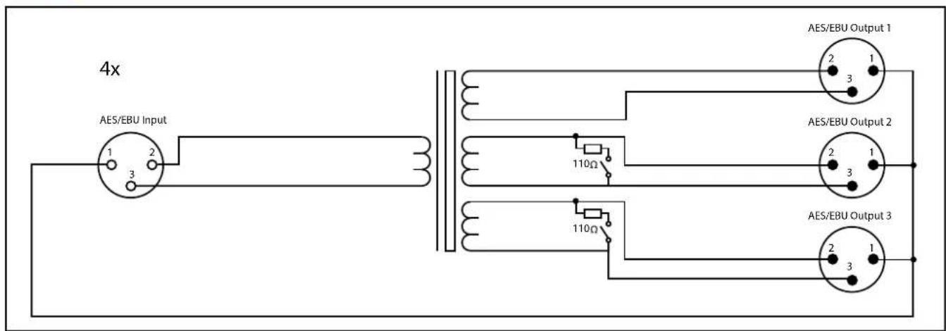
Fig 16-2: RB-AES4X3 System Block Diagram
16 Audio Distribution Amplifier - RB-AES4X3
Controls & Connectors

Fig 16-3: RB-AES4X3 Rear Panel
AES/EBU input(s)
The single digital audio input is via a female XLR connector with the following pin assignment:
Pin 1: 0V Common
Pin 2: Phase
Pin 3: Non Phase
AES/EBU outputs 1-3
The digital audio outputs are via male XLR connectors with the following pin assignment:
Pin 1: 0V Common
Pin 2: Phase
Pin 3: Non Phase
Termination switches
It is possible to terminate Output 2 and Output 3 with 110Ω in the event that they are not connected to a destination device. It may be necessary to remove termination from an unused output if a used output is connected to a destination via a long cable run, in order to increase the level of the AES3 carrier signal.
Technical Specifications RB-AES4X3
Cable drive capability
The table below sets out the minimum signal amplitude required to drive 100m (cumulative) of 110Ω twisted pair cable, based on the sample rate of the digital audio:
| Sample Rate | Minimum Signal Amplitude |
| 32kHz | *2Vpk-pk |
| 44.1kHz | *2Vpk-pk |
| 48kHz | *2Vpk-pk |
| 88.2kHz | 5Vpk-pk |
| 96kHz | 5Vpk-pk |
* Minimum of 2Vpk-pk is defined by the AES3 format specification.
The table below sets out the minimum signal amplitude required to drive 30m (cumulative) of 110Ω twisted pair cable, based on the sample rate of the digital audio:
Sample Rate Minimum Signal Amplitude
| 176.4kHz | 3Vpk-pk |
| 192kHz | 3Vpk-pk |
Audio Specification
| Input & Output Impedances: 110Ω |
| Insertion Loss: 0.17dB 1:1, 1.3dB 1:3 |
| Impedance Match: +/- 2% |
| Max Signal 10 V P-P: Up to 96kHz |
| Attenuation Loss: 0.17dB 1:1, 6.2dB |
Equipment Type
| RB-AES4X3 Quad-3 Way Passive Digital AES3 Splitters, with XLR connections in a 19" rack. |
Physical Specification
| Dimensions (Raw): 48cm (W) x 10.8cm (D) x 4.2cm (H)(1U) |
| 19" (W) x 4.3" (D) x 1.7" (H) (1U) |
| Dimensions (Boxed): 58.5cm (W) x 22.5cm (D) x 7cm (H) |
| 23" (W) x 8.9" (D) x 2.8" (H) |
Weight: Nett: 1.02kg Gross: 1.38kg Nett: 2.25lbs Gross: 3.04lbs
![graph TD A["Source Splitter 100m Short"] --> B["Short"] B --> C["Destination 1"] A --> D["Short"] D --> E["Destination 2"] A --> F["Short"] F --> G["Destination 3"] A --> H["Short"] H --> I["Destination 1"] A --> J["Short"] J --> K["Destination 2"] A --> L["Short"] L --> M["Destination 3"] A --> N["…](/content/2026/05/1083478/images/3425dde3241f003b98ad1c30a22b5a5410f8100b7ad826ce1f4675e65a9dea87.jpg)
17 Audio Distribution Amplifier - RB-MS4X3
17 RB-MS4X3 Quad 3 Way Microphone Splitter
Introduction

Fig 17-1: RB-MS4X3 Front Panel
Controls x 4
The RB-MS4X3 is a passive microphone splitter, designed to split the signal from a single mic or line source, to up to 3 destinations, whilst allowing the operator to pass phantom power back from mic preamplifier inputs, or apply +48VDC power directly from the unit. Pin 1 "ground" lifts are provided to eliminate ground loop problems.
Block Diagram

Fig 17-2: RB-MS4X3 System Block Diagram
Controls & Connectors
Front Panel

Fig 17-3: RB-MS4X3 Front Panel Connections
External +48VDC
This latching push switch applies the external +48V phantom power (if connected) to a microphone connected to the rear panel input connector.
ON LED
The ON LED illuminates when both external +48V phantom power is connected to the rear panel DC socket and the external power is switched to the input.
30dB Pad
It is possible to attenuate the incoming signal by 30dB for example when interfacing a line level signal into a microphone preamplifier. The latching push switch applies and removes the 30dB pad.
Important: Phantom power should be disabled when connecting a line level signal to the splitter input.
Output 2 Toggle switch
This switch controls both the grounding of the output 2 XLR connector (pin 1) and the ability to pass back phantom power (via the internal transformer's centre tap) from output 2 to a mic connected to the splitter's input.
| Switch Position Phantom Loopback (PL) Output 2 | XLR Pin 1 |
| Left Disabled Grounded | |
| Centre Disabled Lifted | |
| Right Enabled Grounded |
Output 3 Toggle Switch
This switch controls the grounding of the output 3 XLR connector.
| Switch Position Phantom Loopback (PL) | |
| Left Grounded | |
| Right Lifted | |
Phantom Powering Guidance
It is possible to pass phantom power to the splitter input by three different methods:
• Via the external +48V DC connector.
- From a mic pre-amp connected to direct output (output 1).
- From a mic pre-amp connected to output 2 (provided phantom loopback is enabled).
It is therefore possible to concurrently power the microphone using any two of the above methods (for power redundancy) without causing signal degradation. It is important the output connectors are grounded (and not lifted) should the external phantom power be connected, to prevent hum/hiss caused by ground loop currents.
Important: A maximum of two phantom powering methods can be used concurrently.
17 Audio Distribution Amplifier - RB-MS4X3
Rear Panel

Fig 17-4: RB-MS4X3 Rear Panel Connections
Input
The XLR 3 pin input socket is transformer balanced and is capable of accepting a dynamic or phantom powered microphone, or a line level signal up to +18dBu (without the 30dB pad applied). The input socket has the following connections:
Pin 1: Screen
Pin 2: Phase
Pin 3: Non Phase
Output 1 (Direct)
The XLR 3 pin plug is a parallel connection of the input. It is therefore possible to supply phantom power to the splitter input by connecting output 1 to a phantom powered microphone preamplifier. The output 1 plug has the following connections:
Pin 1: Screen
Pin 2: Phase
Pin 3: Non Phase
Output 2 (+48V PL Phantom Loopback)
The XLR 3 pin plug is a transformer isolated output. A switchable centre tap connection makes it possible to supply phantom power to the splitter input by connecting output 2 to a phantom powered microphone preamplifier, and setting the front panel toggle switch to the correct position (see front panel controls). The output 2 plug has the following connections:
Pin 1: Screen (Can be grounded or lifted by front panel toggle switch)
Pin 2: Phase
Pin 3: Non Phase
Output 3
The XLR 3 pin plug is a transformer isolated output and has the following connections:
Pin 1: Screen (Can be grounded or lifted by front panel toggle switch)
Pin 2: Phase
Pin 3: Non Phase
Technical Specifications RB-MS4X3
Test
Conditions
Result
Frequency Response Ref. -6dBu, 1kHz 10Hz - 30kHz ±0.5dB
Source Impedance = 150Ω
Load Impedance = 10kΩ
Total Harmonic Ref. +3dBu, 50Hz 0.02%
Distortion Source Impedance = 150Ω
Load Impedance = 10kΩ
Total Harmonic Ref. 0.1%THD+N, 50Hz +13dBu
Distortion 0.1% Source Impedance = 150Ω
Load Impedance = 10kΩ
Total Harmonic Ref. 1%THD+N, 50Hz +18dBu
Distortion 1% Source Impedance = 150Ω
Load Impedance = 10kΩ
Common Mode Ref. 20kHz >60dB
Rejection Ratio Source Impedance = 600Ω
Load Impedance = 10kΩ
Equipment Type
RB-MS4X3

Quad 3 Way Microphone Splitter.
Physical Specification
Dimensions (Raw): 48cm (W) x 10.8cm (D) x 4.2cm (H)(1U)
Fig 17-5: RB-MS4X3 Examples Of Usage
Examples of usage:
![graph TD A["Dynamic Mic"] --> B["Splitter"] B --> C["Main Desk Mic In"] B --> D["Monitor Mixer Mic In"] B --> E["Recorder Mic In"] F["Condenser Mic"] --> G["Splitter"] G --> H["Main Desk Mic In"] G --> I["Monitor Mixer Mic In"] G --> J["Recorder Mic In"] K["Ext Phantom Off 30dB Pad Off +48V PL Off"]…](/content/2026/05/1083478/images/4da0ec3d53e3858be4fac5f67184c1e0acb4bc06ff11ede20ff751ce3a56fbb8.jpg)
18 Phantom Power Supply- RB-MSP6
18 RB-MSP6 6 Way +48V Phantom Power Supply
Introduction

Fig 18-1: RB-MSP6 Front Panel
The RB-MSP6 is a 1U rack-mount phantom power supply, designed to be used in conjunction with up to six RB-MS4X3s, providing mains input redundancy to ensure the target microphones remain powered in the event of a single mains failure.
Two mains AC inlets power separate 48V supplies that are diode fed to six locking DC connector outputs. Each output connector is individually
protected with a resettable fuse rated at 50mA, so a fault on one output will not affect the others.
Should either of the 48V supplies fail, or if their AC power input is removed, the corresponding red front panel LED will extinguish, and a relay alarm output is provided on the rear panel D-Type.
System Block Diagram
![graph LR A["Mains Inlet 1"] --> B["1A Anti-Surge"] C["Mains Inlet 2"] --> D["1A Anti-Surge"] B --> E["AC/DC Converter 20W +48V Out"] D --> F["AC/DC Converter 20W +48V Out"] E --> G["Diode"] F --> H["Diode"] G --> I["50mA Resettable"] H --> J["Locking DC Connector 2.5mm Pin"] I --> K["Alarm Relay"] J…](/content/2026/05/1083478/images/9bec09e5989d3aa01f71dbd545be8f64952bb2f07995e401b7fa5f78bba7d6e8.jpg)
Fig 18-2: RB-MSP6 System Block Diagram
Connections and Operation Front Panel Controls and Indicators

Fig 18-3: RB-MSP6 Front Panel LED Indicators
The RB-MSP6 front panel LEDs (labelled 1 and 2) show the presence of power at the input of each IEC AC supply. Each LED illuminates red if power is present at the input. If a LED extinguishes, it indicates a problem with the corresponding supply. This could be due to one or more of the following:
- The AC mains input is out of range or missing.
• The mains fuse is blown or missing.
• The internal AC/DC 48V supply is faulty.
The current status of the two AC/DC 48V power supplies is also reflected at the remote output port on the rear panel, see below for details.
Rear Panel Connections
AC Mains inputs
The two mains inputs should be connected to 90V – 264V, 47 – 63Hz AC mains supplies, and protected with a 1A anti-surge fuse.
+48V Phantom Power Outputs
The DC outputs each provide up to 50mA of phantom power (48V) to an externally connected RB-MS4X3. The connectors are locking to prevent accidental unplugging, and the positive voltage is on the 2.5mm centre pin.

Alarm Outputs (ALARMS)
The 9 way D-Type socket contains alarm outputs that monitor the status of the two 48V power supplies. A changeover relay provides a normally open (NO), normally closed (NC) and a common connection for each supply. The pinout of the D-Type connector is shown below.
Note: "Normally closed" refers to the pin that is connected to the common when the corresponding supply is working normally.

Fig 18-4: RB-MSP6 Rear Panel Connections
18 Phantom Power Supply- RB-MSP6
Pin Number Connection
1 Supply 1 Normally Open (NO)
2 Supply 1 Common
3 Supply 1 Normally Closed (NC)
6 Supply 2 Normally Open (NO)
7 Supply 2 Common
8 Supply 2 Normally Closed (NC)
4,5,9 No Connection
Example:
The diagram below shows a fault scenario where the mains connection to Supply 2 has been unplugged. The front panel LED is no longer illuminated, and the relay has switched, creating a connection between pins 6 and 7 of the ALARMS D-Type.
Technical Specifications RB-MSP6
Mains inputs 2 x Filtered IEC, 90V-264V, 47-63Hz, fused, 20W maximum
Fuse Ratings 2 x Anti-surge fuse 1A 20 x 5mm
Phantom Power Outputs 6 x locking DC connectors, 2.5mm pin, 48VDC, 50mA maximum current, protected by resettable fuse.
Equipment Type:
RB-MSP6: RB-MSP6 6 way phantom power supply
Physical Specification:
Dimensions (Raw): 28cm (W) x 10.8cm (D) x 4.2cm (H) (1U) 11" (W) x 4.3" (D) x 1.7" (H) (1U)
Dimensions (Boxed): 36cm (W) x 20.5cm (D) x 6cm (H) 14.2" (W) x 8" (D) x 2.4" (H)
Weight: Nett: 1.14kg Gross: 1.52kg Nett: 2.50lbs Gross: 3.34lbs
Accessories:
RB-RK2: 1U rear panel rack kit for small Redbox range

Fig 18-5: RB-MSP6 Fault Scenario Diagram
Notes
SONIFEX
www.sonifex.co.uk
t:+44 (0)1933 650 700
f:+44 (0)1933 650 726
sales@sonifex.co.uk


- REDBOX HANDBOOK 4
- CONTENTS
- FIGURES
- SONIFEX
- REGISTER ONLINE FOR AN EXTENDED 2 YEAR WARRANTY
- WARRANTY
- PRODUCT WARRANTY - 2 YEAR EXTENDED
- SONIFEX WARRANTY & LIABILITY TERMS & CONDITIONS
- DEFINITIONS
- UNPACKING YOUR PRODUCT
- CE CONFORMITY
- ITEM
- QUANTITY
- REPAIRS & RETURNS
- SAFETY & INSTALLATION OF MAINS OPERATED EQUIPMENT
- VOLTAGE SETTING CHECKS
- FUSE RATING
- POWER CABLE & CONNECTION
- WEEE DIRECTIVE
- ATMOSPHERE/ENVIRONMENT
- FITTING REDBOXES
- SAFETY & INSTALLATION
- 1 RB-DA6 6 WAY STEREO DISTRIBUTION AMPLIFIER
- INTRODUCTION
- SYSTEM BLOCK DIAGRAM
- 1 AUDIO DISTRIBUTION AMPLIFIER - RB-DA6
- INPUTS (LEFT AND RIGHT)
- STEREO OUTPUTS 1-6 (MONO OUTPUTS 1-12)
- INPUT GAIN CONTROL
- STEREO/MONO OPERATION
- TECHNICAL SPECIFICATIONS RB-DA6
- AUDIO SPECIFICATIONS
- CONNECTIONS
- EQUIPMENT TYPE
- PHYSICAL SPECIFICATIONS
- 2 AUDIO DISTRIBUTION AMPLIFIER - RB-DA6G
- 2 RB-DA6G 6 WAY STEREO DISTRIBUTION AMPLIFIER WITH OUTPUT GAIN CONTROL INTRODUCTION
- OUTPUT GAIN CONTROL
- TECHNICAL SPECIFICATIONS RB-DA6G
- 3 RB-DA6P 6 WAY STEREO DISTRIBUTION AMPLIFIER
- 3 AUDIO DISTRIBUTION AMPLIFIER - RB-DA6P
- CONNECTIONS AND OPERATION
- STEREO OUTPUTS 1-6
- (MONO OUTPUTS 1-12)
- TECHNICAL SPECIFICATIONS RB-DA6P
- 4 AUDIO DISTRIBUTION AMPLIFIER - RB-DA6R
- 4 RB-DA6R 6 WAY STEREO DISTRIBUTION AMPLIFIER WITH RJ45 OUTPUTS
- BALANCED INPUTS
- UNBALANCED INPUTS
- INPUT SELECTOR SWITCH
- TECHNICAL SPECIFICATION RB-DA6R
- 5 AUDIO DISTRIBUTION AMPLIFIER - RB-DA6RG
- 5 RB-DA6RG 6 WAY STEREO DISTRIBUTION AMPLIFIER WITH RJ45 OUTPUTS
- TECHNICAL SPECIFICATION RB-DA6RG
- 6 AUDIO DISTRIBUTION AMPLIFIER - RB-DA4X5
- 6 RB-DA4X5 4 INPUT, 4 X 5 OUTPUT DISTRIBUTION AMPLIFIER/MIXER
- AUDIO INPUTS 1-4
- D-TYPE AUDIO OUTPUT GROUPS 1-4
- FUNCTION OUTPUT 1 OUTPUT 2 OUTPUT 3 OUTPUT 4 OUTPUT 5
- MONITOR LEDS
- INPUT LEVEL ADJUSTMENT
- OUTPUT LEVEL ADJUSTMENT
- ROUTING SELECTION
- ALIGNMENT TEST TONE
- TECHNICAL SPECIFICATIONS RB-DA4X5
- 7 AUDIO DISTRIBUTION AMPLIFIER - RB-DA24MD
- 7 RB-DA24MD 24 WAY MONO AUDIO DISTRIBUTION AMPLIFIER
- INPUTS (1&2)
- OUTPUTS (1 - 24)
- LF ROLL OFF FILTER
- DUAL MONO/MIXED MONO OPERATION
- MIXED MONO SETTINGS
- 8 AUDIO DISTRIBUTION AMPLIFIER - RB-DDA6A
- 8 RB-DDA6A 6 WAY STEREO AES/EBU DIGITAL DISTRIBUTION AMPLIFIER
- AES/EBU INPUT
- AES/EBU OUTPUTS
- REAR PANEL CONNECTIONS AND OPERATIONS
- TECHNICAL SPECIFICATIONS RB-DDA6A
- 9 RB-DDA6A-2P 6 WAY STEREO AES/EBU DIGITAL DISTRIBUTION AMPLIFIER WITH DUAL POWER SUPPLIES
- 9 AUDIO DISTRIBUTION AMPLIFIER - RB-DDA6A-2P
- ALARM CONNECTOR
- TECHNICAL SPECIFICATION RB-DDA6A-2P
- 10 RB-DDA6A3 6 WAY STEREO AES-3ID DIGITAL AUDIO DISTRIBUTION AMPLIFIER
- AES-3ID INPUT
- AES-3ID OUTPUTS
- 10 AUDIO DISTRIBUTION AMPLIFIER - RB-DDA6A3
- TECHNICAL SPECIFICATIONS RB-DDA6A3
- 11 AUDIO DISTRIBUTION AMPLIFIER - RB-DDA6S
- 11 RB-DDA6S 6 WAY STEREO S/PDIF DIGITAL DISTRIBUTION AMPLIFIER
- S/PDIF INPUT
- S/PDIF OUTPUTS
- TECHNICAL SPECIFICATIONS RB-DDA6S
- 12 RB-DDA6W 6 WAY WORD CLOCK DISTRIBUTION AMPLIFIER
- WORD CLOCK INPUT
- WORD CLOCK OUTPUTS
- 12 AUDIO DISTRIBUTION AMPLIFIER - RB-DDA6W
- TECHNICAL SPECIFICATIONS RB-DDA6W
- SIGNAL SPECIFICATIONS
- 13 RB-DDA6W-2P 6 WAY WORD CLOCK DISTRIBUTION AMPLIFIER WITH DUAL POWER SUPPLIES
- 13 AUDIO DISTRIBUTION AMPLIFIER - RB-DDA6W-2P
- TECHNICAL SPECIFICATION FOR RB-DDA6W-2P
- AUDIO SPECIFICATION
- PHYSICAL SPECIFICATION
- 14 AUDIO DISTRIBUTION AMPLIFIER - RB-DDA22
- 14 RB-DDA22 DIGITAL AUDIO DISTRIBUTION AMPLIFIER WITH MULTIPLE OUTPUTS
- INPUT SIGNALS
- OUTPUT SIGNALS
- OPERATING MODE
- INPUT SELECT MODE
- AUTO SELECT MODE
- DIGITAL AUDIO INPUTS
- AES/EBU INPUTS
- OPTICAL INPUT
- DIGITAL AUDIO OUTPUTS
- OPTICAL OUTPUTS
- TECHNICAL SPECIFICATIONS RB-DDA22
- 15 AUDIO DISTRIBUTION AMPLIFIER - RB-AES4B3
- 15 RB-AES4B3 QUAD 3 WAY PASSIVE AES-3ID SPLITTERS WITH BNC CONNECTORS
- AES/EBU INPUT(S)
- AES/EBU OUTPUTS 1-3
- TERMINATION SWITCHES
- TECHNICAL SPECIFICATION RB-AES4B3
- CABLE DRIVE CAPABILITY
- 16 RB-AES4X3 QUAD 3 WAY AES3 SPLITTER XLR CONNECTORS
- 16 AUDIO DISTRIBUTION AMPLIFIER - RB-AES4X3
- TECHNICAL SPECIFICATIONS RB-AES4X3
- 17 AUDIO DISTRIBUTION AMPLIFIER - RB-MS4X3
- 17 RB-MS4X3 QUAD 3 WAY MICROPHONE SPLITTER
- BLOCK DIAGRAM
- EXTERNAL +48VDC
- ON LED
- 30DB PAD
- OUTPUT 2 TOGGLE SWITCH
- OUTPUT 3 TOGGLE SWITCH
- PHANTOM POWERING GUIDANCE
- INPUT
- OUTPUT 1 (DIRECT)
- OUTPUT 2 (+48V PL PHANTOM LOOPBACK)
- OUTPUT 3
- TECHNICAL SPECIFICATIONS RB-MS4X3
- 18 PHANTOM POWER SUPPLY- RB-MSP6
- 18 RB-MSP6 6 WAY +48V PHANTOM POWER SUPPLY
- CONNECTIONS AND OPERATION FRONT PANEL CONTROLS AND INDICATORS
- REAR PANEL CONNECTIONS
- AC MAINS INPUTS
- 48V PHANTOM POWER OUTPUTS
- ALARM OUTPUTS (ALARMS)
- PIN NUMBER CONNECTION
- EXAMPLE
- TECHNICAL SPECIFICATIONS RB-MSP6
- ACCESSORIES
Brand : Sonifex
Model : Redbox RB-DA6RG
Category : Receiver