
EG-PMS2-WLAN - Power strip EnerGenie - Free user manual and instructions
Find the device manual for free EG-PMS2-WLAN EnerGenie in PDF.


| Product Type | Programmable Surge Protector with WLAN Interface |
| Brand | EnerGenie |
| Model | EG-PMS2-WLAN |
| Input Voltage | Up to 250 VAC, 50-60 Hz |
| Maximum Load Current | 10 A |
| Maximum Power Consumption | 3.5 W |
| Wireless Standard | IEEE 802.11 b/g |
| Surge Protection | Type 3, Up = 1.2 kV (L-N), Uoc = 4 kV (L-N) |
| Number of Sockets | 6 (2 non-manageable, 4 individually manageable) |
| Manageable Sockets Control | Via web browser, Power Manager software, or hardware schedule |
| Remote Access | Via EnerGenie.com account (free), no external IP required |
| Hardware Schedule Events | Up to 45 independent events per socket |
| Timer Accuracy | Less than 2 seconds error per day (with continuous power) |
| Built-in Battery | Keeps timer schedule active during power loss (charge time: 1 day) |
| Security | IP filter, 64-bit password encrypted data encryption |
| Dimensions (W x D x H) | 378 x 98 x 55 mm |
| Net Weight | 1 kg |
| Indoor Use Only | Yes |
| Package Contents | EG-PMS2-WLAN, user manual, USB configuration cable, WLAN antenna, CD with Power Manager software |
| Maintenance | Clean with a dry cloth; do not use liquids |
| Safety Notes | Do not plug several sockets in line; do not use if covered; de-energized only when unplugged; never connect appliances that do not allow unattended operation |
| Spare Parts / Repairability | Contact manufacturer or authorized service center for replacement parts and repairs |
Frequently Asked Questions - EG-PMS2-WLAN EnerGenie
User questions about EG-PMS2-WLAN EnerGenie
0 question about this device. Answer the ones you know or ask your own.
Ask a new question about this device
Download the instructions for your Power strip in PDF format for free! Find your manual EG-PMS2-WLAN - EnerGenie and take your electronic device back in hand. On this page are published all the documents necessary for the use of your device. EG-PMS2-WLAN by EnerGenie.
USER MANUAL EG-PMS2-WLAN EnerGenie
natural_image
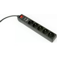
Black power plug with six charging outlets and a red switch, no visible text or symbols on the device itself.USER MANUAL
HANDBUCH
HANDLEIDING
MANUEL DESCRIPTIF
PROTECTOR WITH WLAN INTERFACE
Programmable surge protector with WLAN interface

- Do not plug several sockets in line
- Do not use if covered
- De-energized only if power plug is unplugged
- NEVER connect appliances which do not allow unattained operation!



1. Introduction
Congratulations with your purchase of this Programmable WLAN Surge protector. Your EG-PMS2-WLAN is an advanced surge protector with power management features. Four sockets are individually manageable via your local WiFi network or the internet.
The sockets can be switched on/off by a timer schedule, manually by user or by different programmable events. It is also possible to pre-program the unit event timer schedule (hardware schedule) and then disconnect EG-PMS2-WLAN from WLAN and use it elsewhere. The device can be used as an advanced standby-killer.
With your free personal user account at EnerGenie.com you can manage your EG-PMS2-WLAN via the Internet from all over the world, even from your smartphone.
1.1. Features
- Switch individual sockets on/off manually from your computer
- Switch individual sockets on/off by a programmable timer schedule
- Switch individual sockets on/off whenever a certain software event occurs (e.g. Windows/other software start-up/shutdown, print spooler starting and finishing its job, etc)
-
Because of the LAN interface and the built-in web-server, EG-PMS2-WLAN can be accessed from any computer within your local network (via an Internet browser or Power manager software)
-
It is also possible to assign an external IP-address to EG-PMS2-WLAN, to enable worldwide remote access via the Internet
- No external IP-address at home? No problem. Create your own user account on EnerGenie.com to manage your EG-PMS2-WLAN via Internet with any PC or smartphone. Switching on your coffee maker before setting off for home becomes a reality.
- IP-filter 64-bit password protected data encryption guarantees secure Internet access to EG-PMS2-WLAN
- EG-PMS2-WLAN has a built-in battery for the timer schedule, so the timer schedule remains active even when EG-PMS2-WLAN is temporarily turned off.
1.2. Specifications
- Input voltage: up to 250 VAC, 50 – 60 Hz
• Maximum load current: 10 A
• Maximum power consumption: 3.5 W
• Built-in power supply
• Wireless LAN: IEEE 802.11 b/g - Surge: Type3, Up = 1.2 kV for L-N, Uoc = 4 kV for L-N Uo = 230 V Uc = 250V Ucs = 1.1 x 230 V = 253 V
• Hardware schedule possibilities:
- Maximum number of independent hardware schedule events – 45 per socket
• Time setting accuracy in seconds
- Combine periodical and once events
- Timer accuracy: not more than 2 seconds error per day in case that power is always present. Otherwise there can be an additional up to 2 seconds error per each "power off"
- Indoor use only
• Dimensions: 378 x 98 x 55 mm - Net weight: 1 Kg
1.3. Hardware requirements
- Local area network with WLAN router
- Any Internet-enabled computer connected to the local area network
- Computer running Windows® 2000/XP/7/8/10 is required for using the Power Manager software (use of this software is not compulsory)
1.4. Package contents
- EG-PMS2-WLAN
- User manual and Quick installation guide
• USB configuration cable - WLAN antenna
• CD with Power Manager software for Windows
2. Indicators and controls of the EG-PMS2-WLAN
Figure # 1

All brands and logos are registered trademarks of their respective owners
2.1. Side panel #1

All brands and logos are registered trademarks of their respective owners
Figure # 3

All brands and logos are registered trademarks of their respective owners
2.2. Indicators
- Main rocker switch Z (see Figure #1 above) is lit – this means that EG-PMS2-WLAN is connected to the power supply and active
- Power indicator (see Figure #1 above) is lit – this means that the non-manageable sockets (marked with the sign) are switched on
- The indicator Socket 1 (2,3,4) (see Figure #1 above) is lit – this means that this particular socket is switched on
- The indicator WLAN activity (see Figure #2 above) blinks green – this means that there is some WLAN activity taking place
- The indicator WLAN activity (see Figure #2 above) lights green – this means that EG-PMS2-WLAN is trying to connect to wireless router after power on.
3. Installation
- It is strongly recommended to avoid damp or wet places for installation.
- EG-PMS2-WLAN should be connected to the European AC wall socket of the standard DIN 49 440.
3.1. Getting started
- Screw the supplied antenna into the antenna socket of EG-PMS2-WLAN.
- Connect EG-PMS2-WLAN to the wall socket.
- EG-PMS2-WLAN can now be switched on and off by means of the Main rocker switch (Z).
- Two (the first and the last) sockets of EG-PMS2-WLAN are marked with the symbol. These two sockets are switched on and off by means of the Main rocker switch (Z) and cannot be managed by the computer – so they are called non-manageable sockets in this manual.
- If EG-PMS2-WLAN is switched on then the red indicator POWER is lit. In this case both non-manageable sockets are now live and connected to the power supply.
- The sockets: Socket 1, Socket 2, Socket 3 and Socket 4 can be managed or pre-programmed by computer via LAN. They are called manageable sockets in this manual.
- The manageable sockets of EG-PMS2-WLAN can be programmed to be on or off. The current status of each manageable socket is represented by the corresponding indicator which will be lit if socket has power to it.
- If the Main rocker switch (Z) (see Figure #1 above) is turned off then the manageable sockets cannot be switched on by either web server, Power manager software or the hardware schedule.
- As soon as you turn the Main rocker switch (Z) on then the web server, Power manager software or the hardware schedule will be able to turn the manageable sockets on and off.
- Master switch button (B) (see Figure #2 above) can also switch all the manageable sockets on and off regardless of their current status or schedule that is being executed. To switch them on you should keep the button pressed for 1-2 seconds. To switch them off you should keep the button pressed for more than 3 seconds.
- To protect the connected devices from possible high current and short circuit EG-PMS2-WLAN is equipped with the automatic circuit breaker.
- NOTE: If the total power consumption (or peak power) of the devices, connected to EG-PMS2-WLAN exceeds 2500 Watts, the circuit breaker may power EG-PMS2-WLAN off. In this case, please, remove the excessive load first and then (after 2-3 minutes) press the main rocker switch (Z) to restore the power supply (see Figure #3 above). To be able to use EG-PMS2-WLAN you will now have to complete its WLAN configuration.
3.2. Power Manager software installation
For EG-PMS2-WLAN to connect to your wireless router you should configure it first. To do that, please, follow the steps below:
- For the configuration you will have to use any PC which is located within the reach of your wireless network.
- Insert the Power Manager CD into the PC CD-ROM drive.
- If for any reason the automatic setup does not work, then open CD-ROM drive in the My Computer window and launch SETUP.EXE from the CD
- If your laptop does not have CD-ROM player, just download the latest software from www.energenie.com
- Follow instructions of the WLAN Config software (see below).
3.3. WLAN and local network configuration
After software installation the WLAN Config utility will be started. Once it appears on the screen, power your EG-PMS2-WLAN on and connect it to the PC with the supplied USB cable. The device status will change to "Device is found" (see Figure #4 below).
To configure the device you will need to know the parameters of your WLAN router: network name (SSID), authentication type and password (Network key). These are the same parameters you also use when connecting your PC to your WiFi network. Input these parameters into the
corresponding fields in the WLAN config window, then press the "Configure" button.
Figure # 4

The configuration might take some time - wait until it is completed. If you see a string “Connected to SSID:” (as shown on Figure #5 below) it means that the connection to the wireless router has been successful.
All brands and logos are registered trademarks of their respective owners
Figure # 5

If your router has a DHCP server, it will assign IP address to EG-PMS2-WLAN automatically. Alternatively, you could input them manually using the checkbox “Manual IP settings” and then entering IP settings into the corresponding fields. Don’t forget to press the “Configure” button to complete the manual IP configuration.
All brands and logos are registered trademarks of their respective owners
Now the wireless configuration has been completed. You can now disconnect USB cable from the device. Click “Go to device” button to access the device via web-interface (see section 4 for further details).
Important note: SSID broadcast option must be enabled in WLAN router for successful connection of EG-PMS2-WLAN.
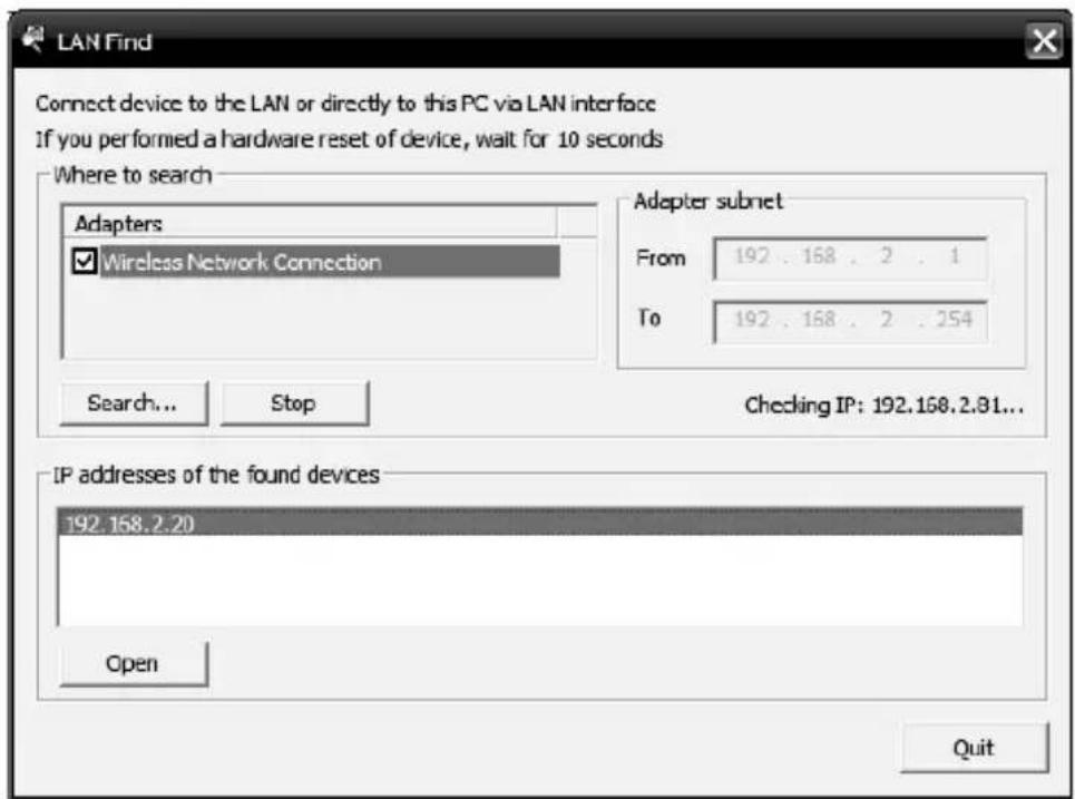
If you ever lost the IP address of EG-PMS2-WLAN on your network, you could use LAN Find utility (See Figure #6 below) to find it. To do that, select your wireless LAN connection from the adapters list, and click “Search” button. The found EG-PMS2-WLAN devices will appear in the list during the search process. When the search is finished, select the desired device from the list and click “Open” button. The window of your default internet browser will then be opened to give you access to the built-in web-server. See section 4 below for the further details.
Figure # 6
All brands and logos are registered trademarks of their respective owners
4. The web server
Your EG-PMS2-WLAN is equipped with a web-server which allows managing the device using any web browser such as Internet Explorer, Firefox, Chrome, etc.
4.1. Web-server login page
To access the web-server of EG-PMS2-WLAN, just open Internet Explorer (or other browser) and input the IP address of EG-PMS2-WLAN (for example http://192.168.1.241). If you have used WLAN Config or Find EG-PMS2-WLAN utilities to locate EG-PMS2-WLAN then you will be taken to this webpage automatically. The login page will then be displayed (see Figure #7 below).
NOTE: Java script must be enabled in your Internet Explorer (or another browser) settings. Otherwise, you get an error message: WARNING! JAVASCRIPT IS DISABLED!
Figure # 7

The default password is 1. It is recommended to change the password on the Device settings page (see section 4.6 below) after the first login.
All brands and logos are registered trademarks of their respective owners
After a successful login you will face the EnerGenie page (see section 4.2 below).
NOTE: There is a possibility that you might then need to open the LAN settings page (see section 4.5 below) to complete the IP configuration.
4.2. EnerGenie page
With the help of EnerGenie page (see Figure #8 below) you will be able to see the status of all your four manageable sockets, and to switch the sockets on and off manually. The status of your sockets, as well as the buttons to switch them on/off are located at the top of the page.
NOTE: the names of the sockets can be changed from the default Socket1/Socket2/Socket3/Socket4 to something meaningful on the page Socket Name Settings (see section 4.4 below).
The EnerGenie page also allows you to setup access and management (switch on and off) of your EG-PMS2-WLAN from anywhere via Internet even if it does not have an external IP address. To setup this free service you should follow two simple steps:
- Register the device. To restrict access to the device via the Internet to the rightful owner only, the device should be registered – e.g.
assigned to your account. To register the device, simply push the button Register on this page (see Figure #6 below). You will then be redirected to Login page of EnerGenie.com. If you already own an account at EnerGenie.com then just enter your login and password on this page and you are done. Otherwise, use the Registration button on the Login page to create a new account. After your successful login (regardless whether you created a new or used an existing account) your EG-PMS2-WLAN is automatically registered.
- Return back to the EnerGenie page of your EG-PMS2-WLAN (see Figure #6 below). Push Activate button to let the device initiate communication with EnerGenie.com server. The EnerGenie page will then start updating itself until the Status becomes Registered Activated Connected (see Figure #8 below).
Figure # 8


flowchart
graph TD
    A["Socket 1 ON OFF"] --> B["Your EnerGenie account"]
    C["Socket 2 ON OFF"] --> B
    D["Socket 3 ON OFF"] --> B
    E["Socket 4 ON OFF"] --> B
    F["Deactivate"] --> G["Login"]
Status: Registered - Activated - Connected
After a successful registration and activation the button Register will be renamed to Login (and will then open the Login page of EnerGenie.com) and the button Activate will turn into Deactivate. If by any reason you would eventually decide to stop managing your EG-PMS2-WLAN from Internet use then Deactivate button to stop communication of the device with EnerGenie.com server.
If you eventually decide to change registration of your EG-PMS2-WLAN and assign it to another account, it will be possible via EnerGenie.com website (see section 5 below).
See section 5 below for further details on managing your EG-PMS2-WLAN via EnerGenie.com website.
4.3. Socket page
There are 4 manageable sockets on EG-PMS2-WLAN and so there are 4 status pages corresponding to them. On each status page you can see the socket status (on or off) and you have the Switch On (Switch Off) button. Besides you can see the scheduled events for this socket.
The socket number and its eventual name (see section 4.4 below) are shown at the very top of the page (see Figure #9 below).
Figure # 9

Socket 1 Socket 1
OFF Switch ON
Set schedule
Event schedule
| Event | Date/Time | |
| ON | Tue Jul 10 2012 14:20:00 GMT+0200 (W. Europe Daylight Time) | Periodic |
| OFF | Tue Jul 10 2012 14:30:15 GMT+0200 (W. Europe Daylight Time) | Periodic |
| ON | Mon Jul 09 2012 14:40.30 GMT+0200 (W. Europe Daylight Time) | |
| OFF | Mon Jul 09 2012 14:50:45 GMT+0200 (W. Europe Daylight Time) | |
Loop period: 1 days
Synchronized: Mon Jul 09 2012 12:37:00 GMT+0200 (W Europe Daylight Time)
Mon Jul 09 2012 14:10:29 GMT+0200 (W. Europe Daylight Time)
The socket shown on the Figure #9 is currently off, it will be turned on again automatically on the 9th of July at 14:40:30 and on the same day at 14:50:45 it will be switched off. Next day it will be turned on at 14:20:00
All brands and logos are registered trademarks of their respective owners
and at 14:30:15 it will be switched off. Last two events will be executed each day staring from the 10 th of July.
Below the page you can see the current time of the web-server and eventual information about the last successful timer synchronization. Automatic timer synchronization is used if Use NTP for timer correction option is enabled (see section 4.6 below).
NOTE: If a certain socket has a switching fault, e.g. it should be switched on but the whole device is switched off, or it should be off but it does have voltage, then the warning message Wrong voltage on socket! will be shown above the Event schedule (see Figure #9 above). This message might also indicate that this socket is defective.
For setting up the socket schedule click Set schedule button. You will face then the page shown below (see Figure #10).
Figure # 10

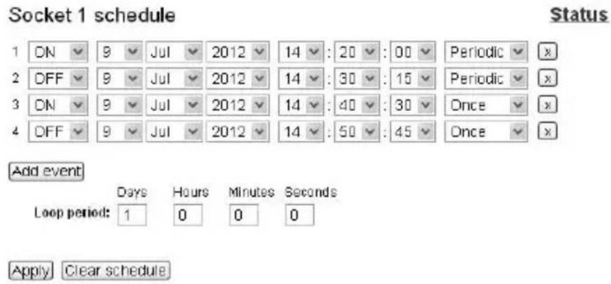
Choose the date and time of the scheduled event. If you wish the events to be executed periodically then check the Loop option and set the
All brands and logos are registered trademarks of their respective owners
loop period. To commit to your changes press the Apply button. To delete the entered schedule press the Clear schedule button.
NOTE: The hardware schedule keeps running even when the device is powered off. However it is recommended not to power off the device for longer than 1 week, because the built-in battery might get discharged then. In this case the internal clock of the device would be reset and as result some schedule events would not be executed. Besides all the sockets would lose their previous status (they will be switched on). In case of an empty battery, just leave the device switched on for one day to fully charge the battery again.
4.4. Socket Name settings page
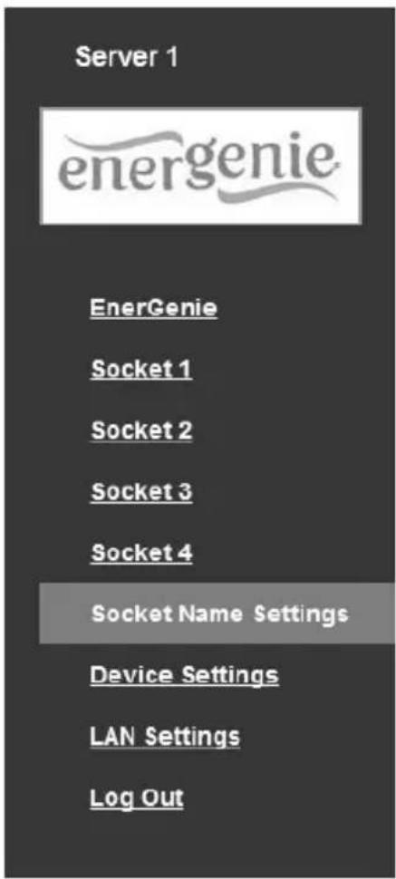
On the Socket name settings page (see Figure #11 below) you can assign an applicable name to your sockets. These names will be shown on EnerGenie page (see section 4.2 above) as well as on the Socket pages (see section 4.3 above).
NOTE: The socket names can not be longer than 11 characters.
HINT: Call your socket by the device which is attached to this socket. For example call Socket 1 – TV set if your TV is connected to this socket.
Figure # 11
Socket Name Settings
| Socket 1 | Socket 1 |
| Socket 2 | Socket 2 |
| Socket 3 | Socket 3 |
| Socket 4 | Socket 4 |
| Apply |
4.5. LAN settings page
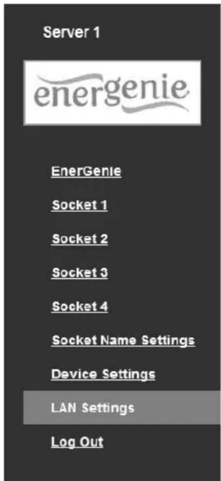
Figure # 12
LAN settings
Obtain IP address automatically (DHCP):
IP address:
Subnet mask:
Gateway:
DNS server:
IP filter:
IP 1:
IP 2:
IP 3:
MAC address:
Power Manager client port:
Network mode:
Wireless Network Name (SSID):
Authentication:
Pass phrase:

192.168.2.20
255.255.255.0
192.168.2.1
172.16.100.1

0.0.0.0
0.0.0.0
0.0.0.0
88B627010010
5000
Access Point
My Wifi router
WPA TKIP
walker78
Apply
On the LAN settings page (see Figure #12 above) you can set up DHCP, IP address, Subnet mask, Gateway, DNS server and IP filter (up to 3 IP addresses can then be enabled for remote access).
The new settings will be applied immediately after you press the Apply button.
IP address, Subnet mask, Gateway, DNS server will be used only if the DHCP option is disabled.
If you set DHCP option it is recommended for your own convenience to set up your DHCP server so that it always provides the same IP address to EG-PMS2-WLAN. To do that you will need to know the MAC address of EG-PMS2-WLAN. It can be found on this page or on the bottom sticker of the device. The MAC address is fixed and cannot be changed.
DNS server address is important to be properly set up in case you wish to enable the NTP timer correction option (see section 4.6 below).
IP filter option is needed to prevent unauthorized access to the server. It restricts the web server access from any computer with IP address different from IP1, IP2 and IP3. Make sure that you input IP1, IP2, and IP3 correctly before enabling this option.
Power Manager client port is used for connecting with the Power Manager software, normally it is not needed to change this setting.
Network mode can be AP mode (device is connected to the wireless router) or Ad-Hoc mode (device might be connected to another WLAN-enabled device in this mode).
Wireless Network Name (SSID) is the name of network, it can be set manually or via the WLAN Configuration utility.
Authentication should correspond to the settings of your wireless router in AP mode. It can be set to WEP64, WEP128, WPA-TKIP, WPA2-AES. With WEP64 or WEP128 authentication modes, you might additionally have to choose the Key index (from 1 to 4, usually 1), which corresponds to that key (pass phrase).
Pass phrase is a password or key, depending on the Authentication type. For WPA-TKIP, WPA2-AES it has to be at least 8 characters long.
4.6. Device settings page
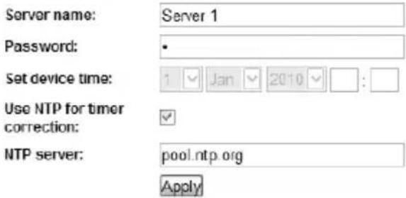
On the device settings page you can setup name, password and internal time of EG-PMS2-WLAN (see Figure #13 below).
Figure # 13

Device settings
All brands and logos are registered trademarks of their respective owners
To be able to setup the schedule of EG-PMS2-WLAN you have to first setup its internal clock correctly. Enter the current local time and date.
Alternatively if the option Use NTP for timer correction is enabled (by default) then the time will be taken from NTP server. The device will try to connect with the server every 18 hours. The first synchronization would take place in 15 seconds after you press the Apply button.
NTP server field should have a valid name of NTP server (by default "pool.ntp.org"). If for any reason the NTP time correction doesn't work you can choose the best NTP server for your country via the website www.pool.ntp.org.
NOTE: for NTP time correction to work properly the device should have access to the Internet and have a proper DNS server setting (see section 4.5 above).
Server name can be convenient to identify the web server if you have more than one EG-PMS2-WLAN. It is “Server 1” by default.
The password is necessary to access EG-PMS2-WLAN both from your web browser and the Power Manager software (see section 6 below). This password is case-sensitive and can be up to 32 characters long. Alphanumeric characters and spaces are allowed to be entered. Only the first eight characters of the password are used to access the device with the Power Manager software. You will need to enter this password in the Add LAN device window (see section 7 below).
The Power Manager software accesses EG-PMS2-WLAN via a certain client port (by default 5000). You can change this port to any other except port 80 which is always occupied by the web server.
Don't forget to push the Apply button to save your settings.
4.7. Web-server logout
Having finished working with EG-PMS2-WLAN, choose Log Out in the main menu. If you don't do this, you will be logged automatically after 10 minutes of inactivity. While you are logged to the web server, it can't be accessed from any other computer. If another user tries to access the web server which is running an active session the error message will be shown on the login page: Somebody with another IP has already logged in. Try again later. In the meantime the Power Manager software (see section 6) can still access the EG-PMS2-WLAN.
5. EnerGenie.com device interface
With your free personal account at EnerGenie.com website you will be able to access your EG-PMS2-WLAN from anywhere in the world using any Internet-enabled device (desktop PC, laptop, smartphone etc). See section 4.2 above on how to register your EG-PMS2-WLAN on the server and setup the connection.
5.1. Logging in
To login into your EnerGenie account just open the webpage www.energenie.com/user in your Internet browser and enter your login and password in the login window (see Figure #14 below).
Figure # 14

Check Remember me checkbox for automatic login in the future (the website will then save a cookie on your computer). If you lost your password, click Forgot password button.
All brands and logos are registered trademarks of their respective owners
5.2. Device management page
After a successful login you will see the list of your registered devices and their corresponding sockets (see Figure # 15 below).
Figure # 15
![energenie User: John [change owner] Log out Device3 Last user online: 21-Jul-2011 17:30:15 JP: 86.232.18.145 NAC: 68-86-17-01-90-10Device nub-interface: 151.168.1.20 Socket1 OFF Socket2 ON Socket3 ON Socket4 ON](/content/2026/05/1083022/images/c425a99a3d6d6da7149a8e6cb3c6978ec438cd2386c058b04d1655269f41bc57.jpg)
All brands and logos are registered trademarks of their respective owners
This page will automatically update itself and will keep showing you the time when your device was last seen online (the latest time when the device communicated with the server) and the status of each socket.
Click your user name to change your account settings.
Click the device to change its name and/or transfer it to another account.
Click the sockets to change their names
Click the On/Off buttons to switch the sockets on or off.
NOTE: the switching command can only be properly executed if the device is switched on, connected to the Internet and activated.
NOTE: the Last seen online status information lets you check if the device keeps communicating with the server.
6. Power Manager software
The Power Manager software is designed to support not only EG-PMS2-WLAN but also other power management family products (please visit www.energenie.com).
6.1. Finding EG-PMS2-WLAN
To be able to manage preconfigured EG-PMS2-WLANs, please, do the following:
- Install Power Manager software on a PC connected to your local network. A socket icon will then appear in your system tray
- With a right mouse click on the socket icon you will get access to the Power Manager main menu. Choose LAN devices from the menu (see Figure #16 below)
Figure # 16

The LAN devices window (see Figure #17 below) will appear, click Add button there to add a new EG-PMS2-WLAN device.
All brands and logos are registered trademarks of their respective owners
Figure # 17

In the Add LAN device window (see figure #18 below) please, enter correct IP address, port number (5000 by default) and password (1 by default) as configured on the Device settings page (see section 4.6 above) of the web server. To disconnect from the device uncheck the option Enable, set this option again to regain the access. Click OK button to return to the LAN devices window.
All brands and logos are registered trademarks of their respective owners
Figure # 18

Specified device should then appear with a green square next to it and Connected status in the LAN devices window (see Figure #19 below).
NOTE: Antivirus or firewall software may block connection to EG-PMS2-WLAN. Please, configure antivirus/firewall to permit connection to the IP address and port of your EG-PMS2-WLAN
All brands and logos are registered trademarks of their respective owners
Figure # 19

- To edit the WLAN device, select it and click the Edit button, or just double click on the LAN device
- To remove the WLAN device, select it and click the Remove button. You can select multiple WLAN devices using Ctrl and Shift keys. You can also remove all WLAN devices by clicking the Clear button
HINT: Use the popup menu which can be activated by the right mouse button click over the table.
All brands and logos are registered trademarks of their respective owners
If the status of EG-PMS2-WLAN shows the device not to be Connected - it could be due to the following reasons:
- Incorrect IP/Port/Password specified in the Add LAN device window
• PC is not connected to the local network - You are trying to access EG-PMS2-WLAN from the PC which is not allowed to do so. Change PC IP address or change IP filter list in EG-PMS2-WLAN hardware settings (see section 4.5 above)
- EG-PMS2-WLAN is not connected to local network. To check if EG-PMS2-WLAN is on your local network you can do so-called ping test:
- Go to Start->Run
- Type cmd
- Type ping
in the window which would appear
Suppose EG-PMS2-WLAN with IP address 192.168.2.189 is connected to the local network. Then the cmd window will look as shown on the Figure #20 below:
Figure # 20
![Administrator: C:\Windows\system32\cmd.exe Microsoft Windows [Version 6.0.6002] Copyright 2006 Microsoft Corporation. All rights reserved. C:\Users\Administrator>ping 192.168.2.189 Pinging 192.168.2.189 with 32 bytes of data: Reply from 192.168.2.189: bytes=32 time=1ns TTL=128 Reply from 192.168.2.189: bytes=32 time](/content/2026/05/1083022/images/8cb4845a413bd81e3ead92af39e6c775fb68e2f43d688933c52c428b1d960a60.jpg)
- EG-PMS2-WLAN is connected to local network (ping test is ok) but not responding. Reset EG-PMS2-WLAN by pressing the Reset button (A) on the side control panel (see Figure #2 above) or switch it off and then on again (see Figure #1 above)
NOTE: The Reset button A (see Figure #2 above) can sometimes help if EG-PMS2-WLAN can't be accessed or works abnormally. The device will then be restarted. All the IP settings and device settings will remain the same as before, but the server time will be reset and all schedules will become outdated.
All brands and logos are registered trademarks of their respective owners
6.2. Managing EG-PMS2-WLAN
After successful connection, close LAN devices window. You can now start managing EG-PMS2-WLAN via the Power Manager interface. Double click on the socket icon in the system tray or select Open from the popup menu (see Figure #16 above). You will get the window of the main control panel shown on the Figure #21 below.
Figure # 21

All brands and logos are registered trademarks of their respective owners
Sockets should switch on and off (green color means the socket is switched on; red color means the socket is switched off) when you double click on them. Click the Settings button for each socket to access the Settings dialog box (see Figure #22 below).
Figure # 22

All brands and logos are registered trademarks of their respective owners
You can choose a different device and another socket from the Device and Socket drop down list-boxes.
- It is possible to give a name to the device and socket (for example Printer or Scanner) using the Rename button
- Check the System tray checkbox if you want to put the icon of the socket into the system tray. You can choose the icon from drop down list box. Such icon is a fast way to switch the device connected to the socket on/off or check the device status
- You can also assign a hot key to switch the socket on/off. Check the Switch ON and Switch OFF checkboxes and specify the hot keys
- To switch the socket on/off on Windows startup (wake up), check the On Windows startup checkbox and choose the required action
- To switch the socket on/off on the Windows shutdown (sleep), check the On Windows shutdown checkbox and choose the required action
7. Power Manager core features
7.1. Setting up the hardware schedule
Using the Hardware schedule button available from the Settings window (see section 6.2 above) you can create the hardware timer schedule (see Figure #23 below). To add a new record, click the Add button.
Figure # 23

All brands and logos are registered trademarks of their respective owners
- The window Add entry will appear (see Figure #24 below). In the dialog box, specify the required time and the action
Figure # 24

- To edit the record, select it and click the Edit button or just double click on the entry (see Figure #23 above). The window Edit entry will appear
- To remove the record, select it and click the Remove button (see Figure #23 above). You can select multiple entries using Ctrl and Shift keys. You can also remove all entries from the schedule by clicking the Clear button (see Figure #23 above)
- To repeat your event (for example if you want to perform the same events every day) use the Loop button (see Figure #23 above) and
specify the loop time period in the Edit loop period window (see Figure #26 below)
Figure # 26

- After the schedule record has been created, click the Apply button (see Figure #23 above) to save the hardware timer schedule changes. In case of incorrect entries, these will be highlighted and an error message will appear. Click the Apply button again after correcting all the errors
- Use Sync button (see Figure #23 above) to synchronize device timer with PC clock. Note that after synchronization past entries will be removed from the schedule
HINT: Use the popup menu (see Figure #23 above) which can be activated by the right mouse button click over the table.
All brands and logos are registered trademarks of their respective owners
NOTE: The hardware schedule keeps running even when the device is powered off. However it is recommended not to power off the device for longer than 1 week, because the built-in battery might get discharged then. In this case the internal clock of the device would be reset and as result some schedule events would not be executed. Besides all the sockets would lose their previous status (they will be switched on). Leave the device switched on for one day to fully charge the battery.
7.2. Setting up software schedule
Using the Software schedule button available from the Settings window (see section 6.2 above) you can create the software timer schedule (see Figure #27 below).
NOTE: the software timer schedule will only be executed if the managing computer is on and the Power Manager is launched.
Figure # 27
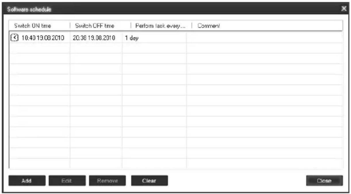
- To add a new task, click the Add button. The Add task window will appear (see Figure #28 below)
All brands and logos are registered trademarks of their respective owners
Figure # 28

In the Add task window, check Switch ON time and/or Switch OFF time checkboxes and specify the time to switch the socked on and/or off. If you want the same event to be performed periodically, check Perform task every checkbox and specify the time interval. You can also add remarks about the task in the Comment field. To disable the task, uncheck the Enabled checkbox and to enable the task again, re-check the checkbox.
All brands and logos are registered trademarks of their respective owners
- To edit the task, select it (see Figure #27 above) and click the Edit button or just double click on the task. The Edit task window will appear (see Figure #29 below)
Figure # 29

- To remove the task select it and click the Remove button (see Figure #27 above). You may select multiple tasks using Ctrl and Shift keys. You can also remove all tasks by clicking the Clear button
All brands and logos are registered trademarks of their respective owners
HINT: Use the popup menu which can be activated by the right mouse button click over the table (see Figure #25 above).
7.3. Setting up application events
Using the Application events window you can specify the socket events when a certain application is launched or closed down. You can also associate switching the sockets off or on with placement and removal of particular files in certain folders.
To use this feature push Application events button available from the Settings window (see section 6.2 above – Figure #22). You will get the following window (see Figure #30 below).
Figure # 30
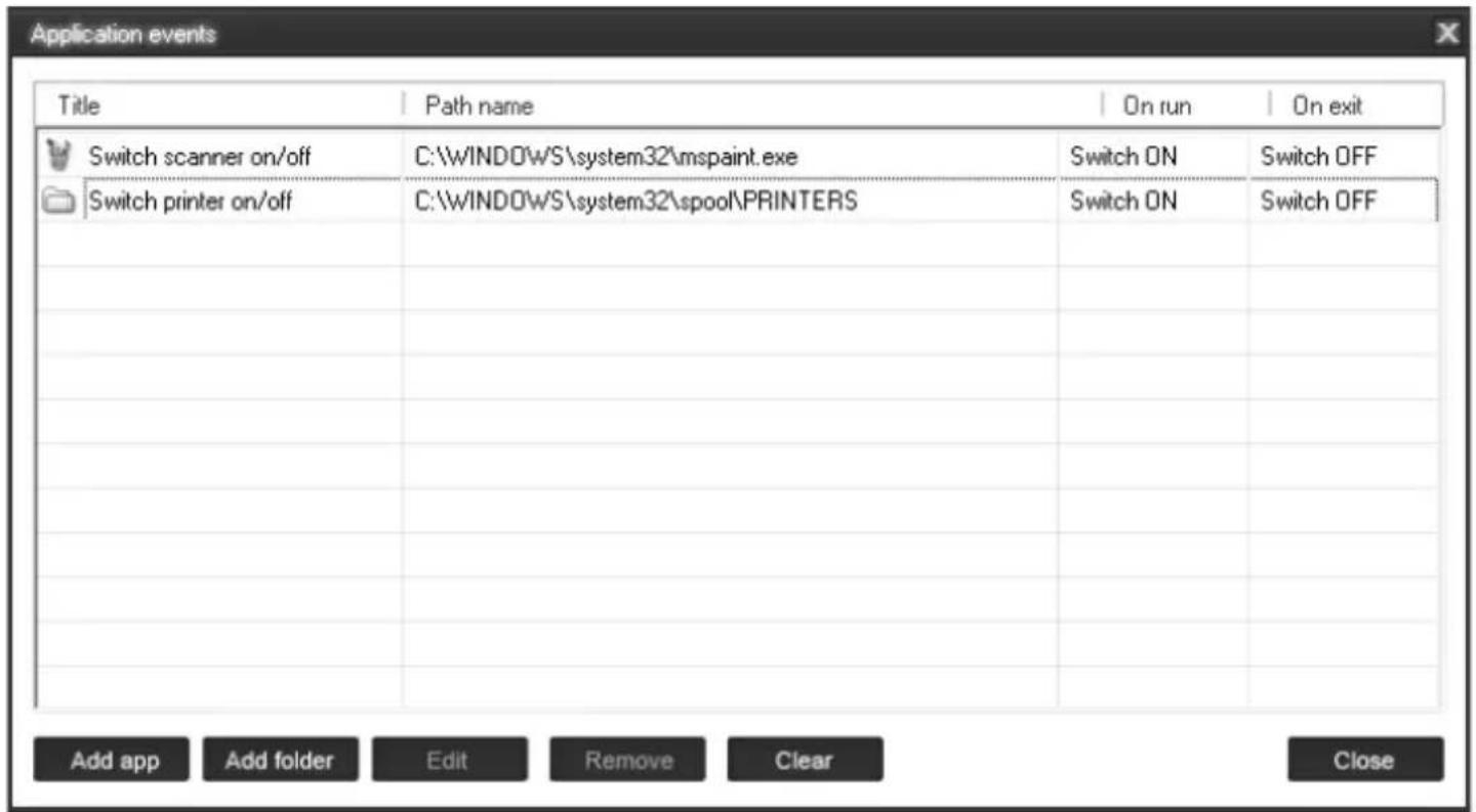
- To add a new program event, click the Add app button. The Add program event dialog will appear (see Figure #31 below)
All brands and logos are registered trademarks of their respective owners
Figure # 31

Specify the application title and path to it using the Browse (...) button or typing it manually in the Title and Path name fields. If you use the Browse (...) button you can also select a shortcut to the application. In this case the application title and path name will be taken automatically via the shortcut if possible. After you have specified the application, check On run and/or On exit and choose the event (switch on or off).
All brands and logos are registered trademarks of their respective owners
NOTE: The On run event will take place when the first window of the selected application is opened. The On exit event will take place when the last window of the application is closed.
HINT: Your device is an advanced standby-killer. Using this feature you can for example switch your scanner on/off whenever Photoshop is started/closed.
- To add a new file event, click the Add folder button (see Figure #30 above). The Add file event window will appear (see Figure #32 below)
Figure # 32

All brands and logos are registered trademarks of their respective owners
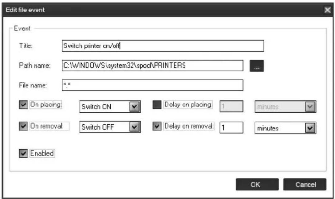
Specify the path to the folder you would like to monitor using the Browse (...) button or typing it manually in the Path name field. Specify the File name mask using wildcard characters: *, ?. Check then On placing and/or On removal checkboxes and select the event and delay.
NOTE: The On placing event will take place when the first file matching the specified file name mask is placed into the specified folder. The On removal event will take place when the last file matching the specified file name mask is removed from the specified folder.
HINT: Your device is an advanced standby-killer. Use the Add folder button to assign c:\system32\spool\printers folder to switch your printer on whenever you start printing and to switch it off again whenever you are ready with printing.
HINT: If you have several printers connected to the same computer, we suggest moving default spool directory of each printer to a separate location.
- To edit the event, select it and click the Edit button, or just double click on the event (see Figure #30 above). The Edit file event window will appear (see Figure #33 below)
Figure # 33
- To remove the event, select it and click the Remove button (see Figure # 30 above). You can select multiple events using Ctrl and Shift keys. You can also remove all events by clicking the Clear button
HINT: Use the popup menu which can be activated by the right mouse button click over the table.
All brands and logos are registered trademarks of their respective owners
8. Managing EG-PMS2-WLAN via your own software
To let you switch the sockets from your own applications the following command line interface syntax is supported:
- pm.exe -[on | off] -device name -socket name
Examples:
- "C:\Program Files\Energenie\Power Manager\pm.exe" -on -My EnerGenie -Socket1
- "E:\Utils\PM3\pm.exe" -off -My EnerGenie -Table lamp
- Execute pm.exe with -info key (pm.exe -info) to get the complete information about the status of the current devices.
For each of the connected devices the following information will then be provided and placed into Info.ini file in the Power Manager folder:
- DeviceName - the user specified device name
- Socket#name, where # is replaced by a certain socket number - the user specified socket name
- Socket#SwitchState, where # is replaced by a certain socket number - TRUE, when the socket is switched on, FALSE, when the socket is switched off
- Socket#VoltageState, where # is replaced by a certain socket number - TRUE, when voltage presence on the socket is detected, FALSE, when there is no voltage on the socket;
Example:
NOTE: Each use of this command line option totally overrides the data in Info.ini file.
NOTE: Power Manager should be active.
9. EG-PMS2-WLAN SDK
For advanced users we offer a software development kit (SDK) to manage the device. Check the SDK manual in SDK folder on the supplied CD to get more information about it, or download the latest SDK from www.energenie.com.
- Troubleshooting
| Problem | Solution |
| The rocker switch turns off. | The load connected to the device is too high, some of the devices connected to the EG-PMS2-WLAN should be disconnected before the rocker switch can be turned on. |
| The switching command is not carried out, the rocker switch and indicators are not lit. | There is no power supply to the EG-PMS2-WLAN. Please, make sure the EG-PMS2-WLAN is connected to the power supply and the rocker switch is switched on. |
| The status of EG-PMS2-WLAN in Power Manager does not become Connected | Maybe network settings problem. Try to ping the device (see section 6.1 above) |
| EG-PMS2-WLAN is connected to local network (ping test is ok) but not responding. | Reset EG-PMS2-WLAN by pressing the Reset button on the side control panel (see Figure #2 above) or switch it off and then on again using the Main rocker switch Z (see Figure #1 above). |
| Connection to EG-PMS2-WLAN is lost. It seems something is wrong with its IP address. | Make sure EG-PMS2-WLAN is connected to WLAN and switched on. Launch LAN Find utility. You can also try to use IP config (C) button to let the device renew its IP address (see section 3.2 above) |
This product is tested and complies with the essential requirements of the laws of member states concerning R&TTE(1999/5/EC). The CE declaration can be found under www.gembird.eu
natural_image
Simple line drawing of a hand holding a tool with water droplets falling (no text or symbols)

natural_image
Simple line drawing of a hand using a tool to cut a screwdriver into a screwdriver (no text or symbols)
natural_image
Simple line drawing of a hand holding a bag with a diagonal line crossing through it, no text or symbols present.63
All brands and logos are registered trademarks of their respective owners
Waste disposal:

Do not deposit this equipment with the household waste. Improper disposal can harm both the environment and human health. For Information about waste collection facilities for used electrical and electronic devices, please contact your city council or an authorized company for the disposal of electrical and electronic equipment.
- Programmable surge protector with WLAN interface
- Introduction
- Features
- Specifications
- Hardware requirements
- Package contents
- Indicators and controls of the EG-PMS2-WLAN
- Side panel #1
- Indicators
- Installation
- Getting started
- Power Manager software installation
- WLAN and local network configuration
- The web server
- Web-server login page
- EnerGenie page
- Socket page
- Socket Name settings page
- Socket Name Settings
- LAN settings page
- LAN settings
- Device settings page
- Device settings
- Web-server logout
- EnerGenie.com device interface
- Logging in
- Device management page
- Power Manager software
- Finding EG-PMS2-WLAN
- Managing EG-PMS2-WLAN
- Power Manager core features
- Setting up the hardware schedule
- Setting up software schedule
- Setting up application events
- Managing EG-PMS2-WLAN via your own software
- Examples:
- EG-PMS2-WLAN SDK
- Waste disposal:
Brand : EnerGenie
Model : EG-PMS2-WLAN
Category : Power strip