
MICA-101 - Graphic tablet Advantech - Free user manual and instructions
Find the device manual for free MICA-101 Advantech in PDF.


| Product Type | Mobile Clinical Assistant (MCA) / Graphic Tablet |
| Brand | Advantech |
| Model | MICA-101 |
| Dimensions (W × D × H) | 255.4 mm × 255.3 mm × 42.75 mm |
| Weight | 1.5 kg (max) |
| Display | 10.4" XGA TFT LCD |
| Touch Panel | Dual mode – Digitizer (pen) & Resistive (finger) |
| Processor | Intel® Atom Processor (Z510 1.1 GHz or Z530 1.6 GHz) |
| Memory | DDR2 667 MHz SODIMM, 2 GB |
| Storage | 1.8" PATA HDD 60 GB (newer B series: SATA HDD) |
| Operating System | Windows XP Professional, XP Embedded, or XP Tablet PC Edition |
| Power Adapter | Input: 100-240 VAC, 47-63 Hz; Output: 15 VDC, 4.2 A max (63 W) |
| Battery | Lithium-ion, 11.1 V, 3760 mAh; up to 5 hours usage; 2.5 hours charging |
| Connectivity | WiFi 802.11 a/b/g/n, Bluetooth V2.0, optional 3.5G, RFID, barcode scanner |
| Ports | 1 × USB 2.0, DC-in, cradle connector, SIM card reader (optional) |
| Camera | 2.0 MP rear camera with LED and autofocus; 1.3 MP front webcam |
| Ingress Protection | IP54 |
| Certifications | FCC Class B, UL, CE, CB60950, CCC, UL60601-1, IEC/EN60601-1 |
| Operating Temperature | 0 °C to 40 °C (32 °F to 104 °F) |
| Storage Temperature | -20 °C to 60 °C (-4 °F to 140 °F) |
| Cleaning | Wipe with a clean damp cloth; do not use phenol, solvents, or abrasive cleaners |
Frequently Asked Questions - MICA-101 Advantech
User questions about MICA-101 Advantech
0 question about this device. Answer the ones you know or ask your own.
Ask a new question about this device
Download the instructions for your Graphic tablet in PDF format for free! Find your manual MICA-101 - Advantech and take your electronic device back in hand. On this page are published all the documents necessary for the use of your device. MICA-101 by Advantech.
USER MANUAL MICA-101 Advantech
Mobile Clinical Assistant (MCA)
10.4" Intel® Atom Processor-based Mobile Clinical Assistant
Copyright
The documentation and the software included with this product are copyrighted 2009 by Advantech Co., Ltd. All rights are reserved. Advantech Co., Ltd. reserves the right to make improvements in the products described in this manual at any time without notice. No part of this manual may be reproduced, copied, translated or transmitted in any form or by any means without the prior written permission of Advantech Co., Ltd. Information provided in this manual is intended to be accurate and reliable. However, Advantech Co., Ltd. assumes no responsibility for its use, nor for any infringements of the rights of third parties, which may result from its use.
Acknowledgements
Intel and Pentium are trademarks of Intel Corporation.
Microsoft Windows and MS-DOS are registered trademarks of Microsoft Corp.
All other product names or trademarks are properties of their respective owners.
Declaration of Conformity
FCC Class B
Note: This equipment has been tested and found to comply with the limits for a Class B digital device, pursuant to part 15 of the FCC Rules. These limits are designed to provide reasonable protection against harmful interference in a residential installation. This equipment generates, uses and can radiate radio frequency energy and, if not installed and used in accordance with the instructions, may cause harmful interference to radio communications. However, there is no guarantee that interference will not occur in a particular installation. If this equipment does cause harmful interference to radio or television reception, which can be determined by turning the equipment off and on, the user is encouraged to try to correct the interference by one or more of the following measures:
■Reorient or relocate the receiving antenna.
■ Increase the separation between the equipment and receiver.
■ Connect the equipment into an outlet on a circuit different from that to which the receiver is connected.
Consult the dealer or an experienced radio/TV technician for help.
Warning! Any changes or modifications made to the equipment which are not expressly approved by the relevant standards authority could void your authority to operate the equipment.

Caution!Danger of explosion if battery is incorrectly replaced.

Replace only with the same or equivalent type recommended by the manufacturer. Dispose of used batteries according to the manufacturer's instructions.
Part No. 2008010100 Edition 1
Printed in Taiwan December 2009
Packing List
Before setting up the system, check that the items listed below are included and in good condition. If any items are missing, please contact your dealer immediately.
■MICA-101 x1
■Stylus pen x1
■Power adapter x1
Battery Pack x1
■USB Type A to Mini B Cable x1
■Software CD (Drivers and Utility, Recovery OS, Recovery Image)
■ Warranty card x1
Warning! To prevent electric shock, Do not remove cover.
No user serviceable parts inside, refer servicing to qualified personnel.

Additional Information and Assistance
- Visit the Advantech websites at www.advantech.com or www.advantech.com.tw where you can find the latest information about the product.
- Contact your distributor, sales representative, or Advantech's customer service center for technical support if you need additional assistance. Please have the following information ready before you call:
– Product name and serial number
– Description of your peripheral attachments
– Description of your software (operating system, version, application software, etc.)
– A complete description of the problem
– The exact wording of any error messages - This equipment is a source of electromagnetic waves. Before use please, make sure that there are not EMI sensitive devices in its surrounding which may malfunction therefore
Warning!
- Input voltage rated 100-240 VAC, 47-63 Hz, 1.62-0.72 A, Output Voltage rated 15 VDC, max 4.2 A
- Use a 3 V @ 210 mA lithium battery (Model No. CR2032)
- Maintenance: to properly maintain and clean the surfaces, use only approved products or clean with a dry applicator

Safety Instructions
- Read these safety instructions carefully.
- Keep this User Manual for later reference.
- Disconnect this equipment from any AC outlet before cleaning. Use a damp cloth. Do not use liquid or spray detergents for cleaning.
-
For plug-in equipment, the power outlet socket must be located near the equipment and must be easily accessible.
-
Keep this equipment away from humidity.
-
Put this equipment on a reliable surface during installation. Dropping it or letting it fall may cause damage.
-
The openings on the enclosure are for air convection. Protect the equipment from overheating. DO NOT COVER THE OPENINGS.
-
Make sure the voltage of the power source is correct before connecting the equipment to the power outlet.
-
Position the power cord so that people cannot step on it. Do not place anything over the power cord.
-
All cautions and warnings on the equipment should be noted.
-
If the equipment is not used for a long time, disconnect it from the power source to avoid damage by transient overvoltage.
-
Never pour any liquid into an opening. This may cause fire or electrical shock.
-
Never open the equipment. For safety reasons, the equipment should be opened only by qualified service personnel.
-
If one of the following situations arises, get the equipment checked by service personnel:
a. The power cord or plug is damaged.
b. Liquid has penetrated into the equipment.
c. The equipment has been exposed to moisture.
d. The equipment does not work well, or you cannot get it to work according to the user's manual.
e. The equipment has been dropped and damaged.
f. The equipment has obvious signs of breakage.
-
DO NOT LEAVE THIS EQUIPMENT IN AN ENVIRONMENT WHERE THE STORAGE TEMPERATURE MAY GO BELOW -20°C (-4°F) OR ABOVE 60°C (140°F). THIS COULD DAMAGE THE EQUIPMENT. THE EQUIPMENT SHOULD BE IN A CONTROLLED ENVIRONMENT.
-
If your computer is losing time significantly or the BIOS configuration resets itself to the default, the battery may have no power.
Caution!

- Do not replace battery yourself. Please contact a qualified technician or your retail provider.
-
The computer is provided with a battery-powered real-time clock circuit. There is a danger of explosion if battery is incorrectly replaced. Replace only with same or equivalent type recommended by the manufacturer. Discard used batteries according to the manufacturer's instructions.
-
IMPROPER INSTALLATION OF VESA MOUNTING CAN RESULT IN SERIOUS PERSONAL INJURY! VESA mount installation should be performed by a professional technician; please contact the service technician or your retailer if you need this service.
-
CLASSIFICATION:
Supply Class I adapter
No applied part
IP54
Continuous Operation
Not AP or APG category
-
Disconnect device: Appliance inlet.
-
Follow national, state or local requirements to dispose of unit.
-
Maintenance: to properly maintain and clean the surfaces, use only the approved products or clean with a dry applicator.
-
Contact information:
No.1, Alley 20, Lane 26, Rueiguang Road Neihu District, Taipei, Taiwan 114, R.O.C.
TEL: +886 2-2792-7818
23.

Medical Equipment
With Respect to Electric Shock,
Fire, and Mechanical Hazards Only,
In Accordance with UL 60601-1,
CAN/CSA C22.2 No. 601.1, and
IEC 60601-1
-
This equipment shall not be used as a life support system.
-
Accessory equipment connected to the analog and digital interfaces must be in compliance with the respective nationally harmonized IEC standards (i.e. IEC 60950 for data processing equipment, IEC 60065 for video equipment, IEC 61010-1 for laboratory equipment, and IEC 60601-1 for medical equipment.) Furthermore all configurations shall comply with the system standard IEC 60601-1-1. Anyone who connects additional equipment to the signal input part or signal output part is configuring a medical system, and is therefore, responsible that the system complies with the requirements of the system standard IEC 60601-1-1. The unit is for exclusive interconnection with IEC 60601-1 certified equipment in the patient environment and IEC 60XXX certified equipment outside of the patient environment. If in doubt, consult the technical services department or your local representative.
-
Users must not allow SIP/SOPs to come into contact with the patient at the same time.
-
The sound pressure level at the operator's position according to IEC 704-1:1982 is no more than 70dB (A).
DISCLAIMER: This set of instructions is given according to IEC 704-1. Advantech disclaims all responsibility for the accuracy of any statements contained herein.
Contents
Chapter 1 General Information ....1
1.1 Introduction 2
1.2 Specifications .... 2 Table 1.1: MICA Specification .... 2
1.3 Touchscreen Specifications .... 4 Table 1.2: Touchscreen Specifications.... 4
1.4 Cleaning/Disinfecting 4
1.5 Dimensions .... 5 Figure 1.1 MICA Dimensions.... 5
Chapter 2 Getting Started....7
2.1 A Quick Tour of MICA 8
Figure 2.1 Front View 8
Figure 2.2 Left Side View....8
Figure 2.3 Right Side View 9
Figure 2.4 Rear View 9
Figure 2.5 Bottom View 10
2.2 A Quick Tour of MICA Cradle (Optional)....10
Figure 2.6 Front View 10
Figure 2.7 Mica-101 in Cradle 10
Figure 2.8 Rear View of Cradle 11
2.3 Installation Procedures.... 11
2.3.1 Powering MICA by Battery Power.... 11 Figure 2.9 Press with Thumb Positioned Here .... 12 Figure 2.10Remove Battery from the System.... 12 Figure 2.11Push Battery Back into Slot .... 13
2.3.2 Connecting the Adapter to MICA .... 14 Figure 2.12Connecting the AC Adapter Power Supplier .... 14
2.3.3 Connecting the Power Cord for the Cradle .... 15 Figure 2.13Connecting the AC Adapter Power Supplier to the MICA Cradle .... 15
2.3.4 Connecting the Keyboard and Mouse.... 16 Figure 2.14Connecting the Keyboard or Mouse .... 16
2.3.5 Switching on the Power 16
2.4 LED Signals .... 16 Figure 2.15LED Signals.... 16
2.4.1 Bluetooth ON/OFF LED 17
2.4.2 RFID ON/OFF LED 17
2.4.3 WiFi ON/OFF LED 17
2.4.4 Power/Battery Status LED 17
2.5 MICA Cradle LED Signals.... 17 Figure 2.16 Cradle LED .... 17
2.5.1 Power LED.... 17 2.5.2 Lan LED.... 17
2.6 Buttons .... 18 Figure 2.17Composite Button .... 18
2.6.1 Barcode Scanner Button.... 18 Figure 2.18Right Side.... 18
2.6.2 Power and P2 button .... 19 Figure 2.19 Left Side buttons.... 19
2.6.3 Battery Removal Button....19 Figure 2.20Battery Removal Button....20
2.7 Running the BIOS Setup Program 20
2.8 Installing System Software.... 20
2.9 Installing the Drivers 21
Figure 2.21 The File Directory on the "Drivers and Utilities" CD-ROM 21
Chapter 3 Using MICA-101....23
3.1 Power on the System.... 24
3.1.1 Digitizer Pen 24
3.1.2 Resistive Touchscreen Calibration Function 26
3.1.3 Digitizer Touchscreen Calibration Function 27
3.1.4 Virtual Keyboard 28
3.2 RFID Function 28
3.3 Barcode Function.... 30
3.4 WLAN On/Off (P2 Button).... 31
3.5 Swap Battery Function (P1 Button) 32
3.6 Touchscreen Disable Function 33
3.7 Camera Function 34
Chapter 4 Graphics Chipset Setup ...... 35
4.1 Introduction 36
4.2 Installation of Chipset Driver 36
4.3 Further Information 39
Chapter 5 Audio Setup....41
5.1 Introduction 42
5.2 Installation of Audio Driver 42
5.3 Further Information 43
Chapter 6 Touchscreen Setup...... 45
6.1 Introduction 46
6.2 Installation of Touchscreen Driver 46
6.3 Further Information 47
Chapter 7 Ethernet Driver Installation ...... 49
7.1 Installation of Ethernet Driver....50
7.2 Further information.... 51
Chapter 8 RFID Driver installation 53
8.1 Introduction 54
8.2 Installation of RFID Driver.... 54
8.3 Further Information 55
Chapter 9 WIFI Driver Installation....57
9.1 Installation of RFID Driver.... 58
9.2 Further Information 62
Chapter 10 Accessories ......63
10.1 Accessory List 64
10.2 Battery Charger....64
10.3 VESA Cradle 64
Figure 10.1 Cradle Dimensions (Optional) 65
Table 10.1:Battery Charger 65
Table 10.2: VESA Cradle Specifications .... 65
Table 10.3:Full Function Cradle 65
Table 10.5:Battery 66
Table 10.6:Carrying Strap 66
Table 10.4:Digitizer Pen 66
10.4 Full Function Cradle 67
Chapter 1
General Information
1.1 Introduction
MICA is a multimedia Atom Mobile processor-based computer that is designed to serve as a Mobile Clinical Assistant (MCA). It is a PC-based system with 10.4" color TFT LCD display and an 18-bit stereo audio controller. MICA is a simple, complete and highly integrated mobile multimedia system which allows system integrators to easily build a Mobile Clinical Assistant Terminal into their applications.
Common industrial applications include factory automation systems, precision machinery, and production process control. It is also suitable for many non-industrial applications, including interactive kiosk systems, entertainment management, and car park automation. MICA is a reliable, cost-effective solution to meet an application's processing requirements.
1.2 Specifications
Table 1.1: MICA Specification
| Item | Description |
| Dimensions (W×D×H) 255.4 mm x 255.3 mm x 42.75 mm | |
| Weight 1.5 kg (Max) | |
| CPU and Chipset | Intel® Atom Processor and Intel® Poulbso SCH- Z510/1.1 GHz (FSB 400 MHz)- Z530/1.6 GHz (FSB 533 MHz) |
| Memory DDR2 667 MHz SODIMM 2GB | |
| Graphics | Intel® Integrated 3D Graphics |
| Audio | Realtek ALC888Integrated speakerx1, Microphone x2 |
| I/O Ports | USB 2.0 x1DC-inCradle connectorCard reader of SIM Card (Optional) |
| Expansion mini-PCIe x1 | |
| Display 10.4" XGA TFT LCD | |
| Touch Panel Dual mode – Digitizer & Resistive | |
| Stylus Pen Electronic stylus pen with side switch and eraser | |
| Storage | 1.8" PATA HDD 60GB (The new B series model will implement a 1.8" SATA HDD) |
| Communication | WiFi- 802.11 a/b/g/n WLANBluetooth V2.03.5 G (Optional) |
| Ingress Protection IP54 | |
| Thermal Solution Fanless Design | |
| Operating System | Windows XP ProfessionalWindows XP EmbeddedWindows XP Tablet PC Edition (optional) |
| Barcode Scanner 1D/2D and UDSI Barcode scanner | |
| RFID | ■ 13.56 MHz RFID with ISO15693 & ISO14443A/B■ Active Tag function |
| Camera | 2.0 Mega pixel camera with LED lightAuto-focus supported |
| Web camera 1.3 M pixel VGA camera | |
| Control Button | Power button: On the left side of MICA |
| Barcode scanner button: On the right side of MICA. | |
| Composite button■Camera snapshot button■RFID read trigger button■Screen lock button■3 programmable buttons (Default setting):- P1 for S3 mode-P2 for WiFi on/off | |
| Indicated LED | Power LED & Battery status LED■Full → Green■ Charging →Green + Purple■Low → Purple |
| RFID LED■Blue LED for RFID read trigger | |
| WiFi LED■Blue LED for enabling Wireless LAN | |
| Bluetooth■Blue flickering LED for enabling Bluetooth | |
| Power Adapter | SINPRO MPU63-106INPUT: 100 ~ 240 V,1.62 ~ 0.72 A, 50/60 HzOUTPUT: 15 V, 4.2 A Max. 63 WCertification: EN 60601-1 |
| Battery | Model: MICALithium-ion battery (11.1 V @ 3760 mAh)2.5 Hr charging time |
| Backup Battery | Model: 6 V 40 HLithium-ion battery 40 mAh24 Hr charging time |
| Power Management | Normal mode: general usingIdle mode: turn-off the LCD backlight only.Suspend mode: S3 (STR) /S4 (STD)Power-off mode: only RTC alive |
| Operating Temperature 0°C ~ 40°C | |
| Operating Humidity 10% ~ 90% @ 40°C, non-condensing | |
| Storage Temperature -20°C ~ 60°C | |
| Storage Humidity | 10% ~ 95%, non-condensing |
| Transportation Temperature | -20°C ~ 60°C |
| Transportation Humidity | 10% ~ 95%, non-condensing |
| Certifications | |
| Safety | FCC Part 15 Class B, UL, CUL, CE, CB60950, CCC,R&TTE (99/5/EC) |
| Medical | UL60601-1, IEC/EN60601-1, CB60601-1, TUV |
| Battery Pack | UL2054 and UN38.3 |
1.3 Touchscreen Specifications
| Table 1.2: Touchscreen Specifications | |
| Item Description | |
| Type Analog Resistive | |
| Resolution Continuous | |
| Light Transmission 75% | |
| Controller USB interface | |
| Power Consumption +5 V @ 100 mA | |
| Software Driver | Supports Windows® XP Professional, Windows® Vista Business |
| Durability (Lifetime Touches) 30 million | |
Note! The MICA Terminal with the optionally installed touchscreen will share a USB port. Once the touchscreen is installed, one USB port is dedicated to this purpose.
1.4 Cleaning/Disinfecting
During normal use MICA may become soiled and should, therefore, be cleaned regularly.
Steps:
- Wipe MICA with a clean cloth that has been moistened in the cleaning solution.
- Prepare agent per manufacturer's instructions or hospital protocol.
- Wipe thoroughly with a clean cloth.
Caution!
Do not immerse or rinse MICA or its peripherals. If you accidentally spill liquid on the device, disconnect the unit from the power source. Contact your Biomed personnel regarding the continued safety of the unit before placing it back in operation.

Do not spray cleaning agent on the chassis.
Do not use disinfectants that contain phenol.
Do not autoclave or clean MICA or its peripherals with strong aromatic, chlorinated, ketone, ether, or esther solvents, sharp tools or abrasives.
Never immerse electrical connectors in water or other liquids.
1.5 Dimensions

Figure 1.1 MICA Dimensions
Chapter 2
Getting Started
2.1 A Quick Tour of MICA
Before you start to set up MICA, take a moment to become familiar with the locations and purposes of the controls, drives, connections and ports, which are illustrated in the figures below.
When placed upright on the desktop, the MICA front panel appears as shown in Figure 2.1.

Figure 2.1 Front View
The power button and P2 buttons are on the top, left side of the tablet PC.

natural_image
Blue handheld device with a curved blade and control buttons (no visible text or symbols)Figure 2.2 Left Side View
The barcode scanner button is on the right side of the tablet PC.

Figure 2.3 Right Side View
The rear view of the tablet PC is depicted in Figure 2-4.

Figure 2.4 Rear View
The bottom side of the tablet PC contains the I/O ports (power jack, USB jack, SIM card slot (Optional)) and charging connector.

natural_image
Close-up of a hand pressing a small electronic device on a silver surface (no visible text or symbols)Figure 2.5 Bottom View
2.2 A Quick Tour of MICA Cradle (Optional)
When you place the MICA cradle upright on the desktop, its front panel appears as shown in Figure 2.6.

natural_image
White plastic kitchen chimney with conical top and base (no text or symbols)Figure 2.6 Front View

natural_image
3D rendering of a medical device with a green screen and blue top (no visible text or symbols)Figure 2.7 Mica-101 in Cradle
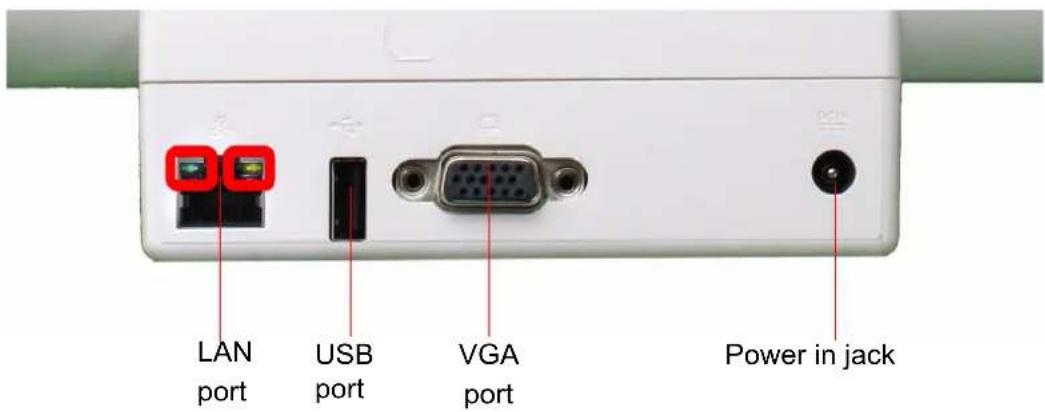
Figure 2.8 Rear View of Cradle
2.3 Installation Procedures
2.3.1 Powering MICA by Battery Power
MICA is supplied with a powerful rechargeable battery. To install, maintain or replace the battery follow the instructions in this section.
Caution! Do not attempt to replace the battery with any others than the models recommended and manufactured specifically for the MICA product.

Note! Before using MICA, please connect the adapter to MICA to charge the battery and backup battery at least 24 Hrs.

2.3.1.1 Installing a Battery
The battery is designed specifically for installation with MICA. It fits exactly into the back of the PC and delivers precisely the exact voltage required to power the unit. Under normal conditions, a fully charged battery will power the PC for up to 5.0 hours. Normally, it requires 2.5 hours to fully charge a new battery.
To install or replace the battery pack:
- Turn off MICA or press P1 button to enter S3 sleep mode
- Press with your thumb positioned as in Figure 2.9 then remove the battery.

natural_image
Close-up of hands installing a blue laptop cover with visible brand labels (no readable text in focus)Figure 2.9 Press with Thumb Positioned Here
- Remove the battery from the system, see Figure 2.10.
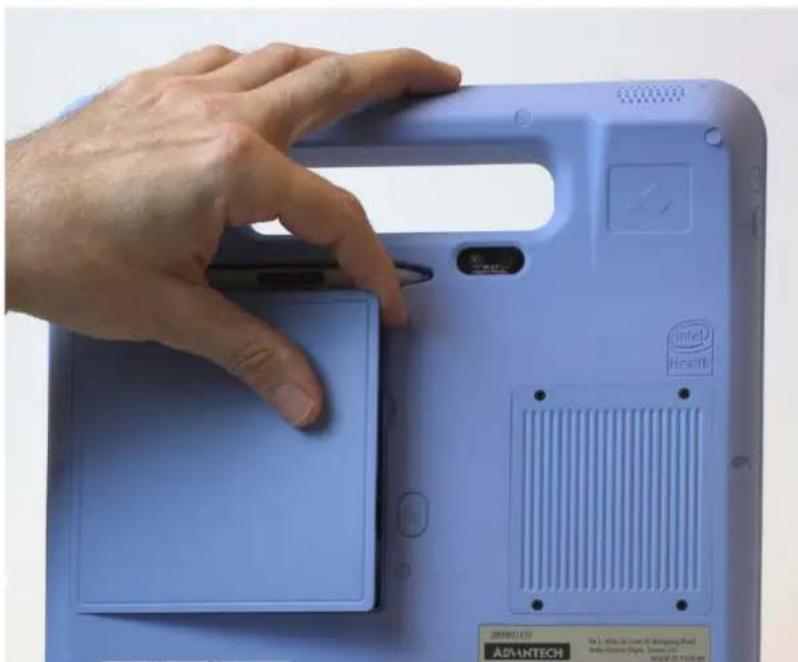
natural_image
Hand pressing a blue electronic device with a 'Intel Health' logo on the cover (no readable text or symbols beyond branding)Figure 2.10 Remove Battery from the System
- Install the battery pack into the slot until you hear a click sound (Figure 2.11)
When using the P1 function key to place the system in S3 sleep mode, the swap process must be completed within 10 minutes. The battery can be changed up to 10 times, each
change taking no longer than 60 seconds. After the fifth swap, it is necessary to plug the MICA-101 into the AC adapter and recharge the internal backup battery for at least 24 hours. During the swap process no LED indicator light is lit. Using S3 sleep mode will extend battery life..

natural_image
Close-up of a person installing or adjusting a blue electronic device with a label (no readable text on device)Figure 2.11 Push Battery Back into Slot
2.3.2 Connecting the Adapter to MICA
Be sure to always handle the power cords by holding the plug ends only.
Follow these procedures in order:
- Connect the end of the AC Adapter cord to the DC Power inlet of MICA (See Figure 2.12.).
- Connect the female end of the power cord to the AC inlet of the AC Adapter.
- Connect the 3-pin male plug of the power cord to an electrical outlet.
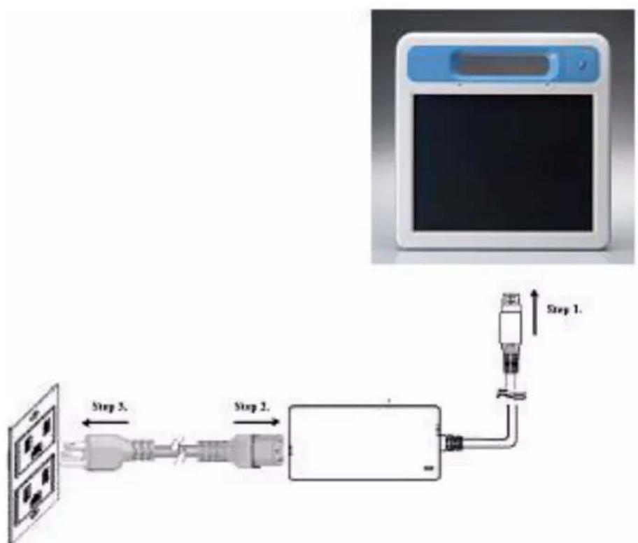
flowchart
graph LR
    A["Device Input"] --> B["Step 2"]
    B --> C["Process Unit"]
    C --> D["Step 1. Monitor"]
Figure 2.12 Connecting the AC Adapter Power Supplier
2.3.3 Connecting the Power Cord for the Cradle
Be sure to always handle the power cords by holding the plug ends only.
Follow these procedures in order:
- Connect the end of the AC Adapter cord to the DC Power inlet of the CRADLE (See Figure 2.13).
- Connect the female end of the power cord to the AC inlet of the AC Adapter
- Connect the 3-pin male plug of the power cord to an electrical outlet.
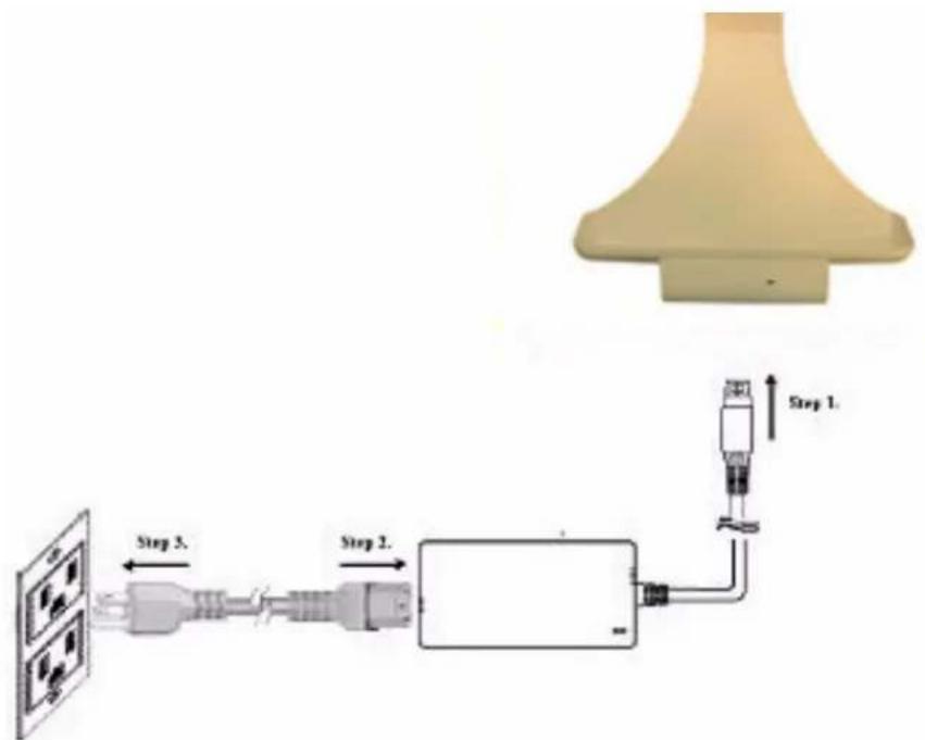
flowchart
graph LR
    A["Light Lamp"] --> B["Step 1."]
    B --> C["Step 2."]
    C --> D["Step 3."]
    D --> E["Output"]
    style A fill:#f9f,stroke:#333
    style B fill:#ccf,stroke:#333
    style C fill:#cfc,stroke:#333
    style D fill:#fcc,stroke:#333
Figure 2.13 Connecting the AC Adapter Power Supplier to the MICA Cradle
2.3.4 Connecting the Keyboard and Mouse
Connect the USB port to the USB mouse and keyboard port on the I/O section of MICA (See Figure 2.14.). The USB transfer cable is bundled in the accessory box. A USB hub is needed for additional USB devices.

natural_image
Illustration of a computer device connected to a screen and mouse, with an arrow indicating the connection (no text or symbols present)Figure 2.14 Connecting the Keyboard or Mouse
2.3.5 Switching on the Power
Switch on the power switch on the left side. Press the power switch button then the system will power on.
2.4 LED Signals
MICA is equipped with a set of Light Emitting Diodes (LEDs) located along the right top of the front Bezel. The LED indicators from left to right are described below.

natural_image
Close-up of a blue phone control panel with buttons and display (no readable text or symbols)Figure 2.15 LED Signals
2.4.1 Bluetooth ON/OFF LED
■Blue flickering: enable Bluetooth function
■Dark: disable Bluetooth function

2.4.2 RFID ON/OFF LED
■Blue: enable RFID function
■Dark: disable Bluetooth function

2.4.3 WiFi ON/OFF LED
■Blue: enable Wireless function
■Dark: disable Wireless function

2.4.4 Power/Battery Status LED
■Green: Full charge
Orange: Low battery
■Green+Orange: Battery charging

2.5 MICA Cradle LED Signals

Figure 2.16 Cradle LED
2.5.1 Power LED
■Blue: Power is present
2.5.2 Lan LED
■Green flashing: 10Base-T Ethernet is supported
■ Yellow flashing: 100Base-TX Fast Ethernet is supported
2.6 Buttons
The Composite button is on the upper right-hand side of the front bezel.

Figure 2.17 Composite Button
2.6.1 Barcode Scanner Button
The barcode scanner function button is on the right side of the unit on the top.

natural_image
Exterior view of a medical device with blue and white casing (no visible text or symbols)Figure 2.18 Right Side
2.6.2 Power and P2 button
The power button and P2 function buttons (default setting for WIFI on/off) are on the left side of the unit on the top.

Figure 2.19 Left Side buttons
2.6.3 Battery Removal Button
The battery removal button is in the center of the back side.
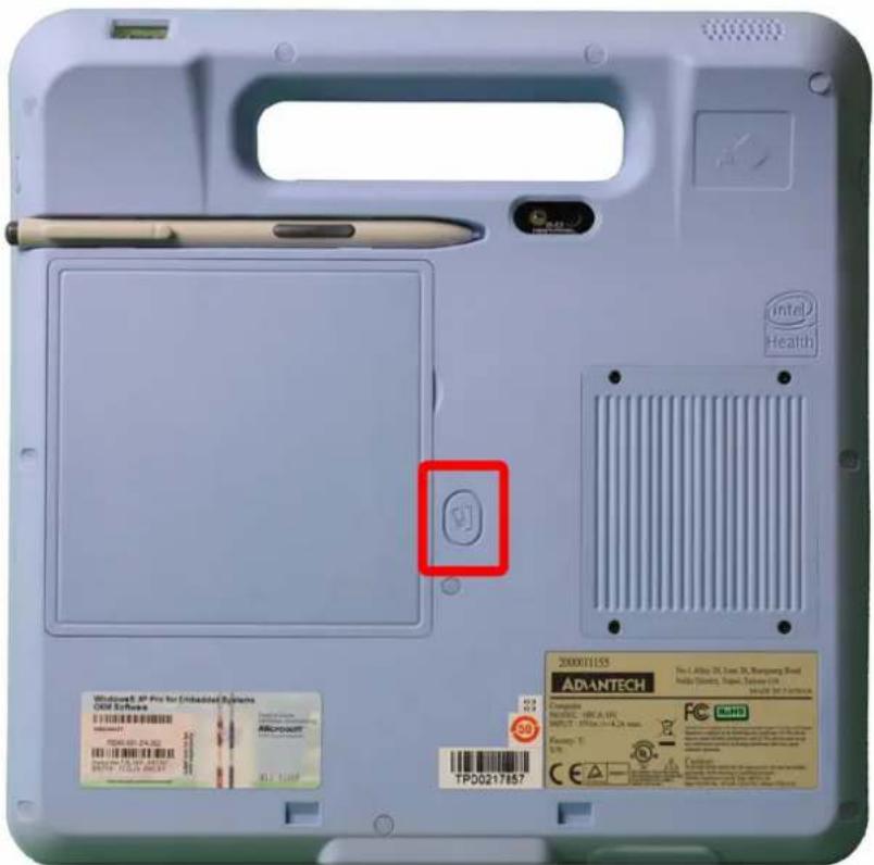
Figure 2.20 Battery Removal Button
2.7 Running the BIOS Setup Program
Your MICA has most likely been properly set up and configured by your dealer prior to delivery. You may still find it necessary to use the BIOS (Basic Input-Output System) setup program to change system configuration information, such as the current date and time or your type of hard drive. The setup program is stored in read-only memory. It can be accessed either when you turn on or reset the tablet PC, by pressing the "Crtl+Alt+Del" key on your keyboard immediately after powering on the computer.
The settings you specify with the setup program are recorded in a special area of memory called CMOS RAM. This memory is backed up by a battery so that it will not be erased when you turn off or reset the system. Whenever you turn on the power, the system reads the settings stored in CMOS RAM and compares them to the equipment check conducted during the power on self-test (POST). If an error occurs, an error message will be displayed on screen, and you will be prompted to run the setup program.
2.8 Installing System Software
Recent releases of operating systems from major vendors include setup programs which load automatically and guide you through hard disk preparation and operating system installation. The guidelines below will help you determine the steps necessary to install your operating system on the tablet PC hard drive.
Note! Some distributors and system integrators may have already pre-
installed system software prior to shipment of your tablet PC.

If required, insert your operating system's installation or setup diskette into the optical drive until the release button pops out.
The BIOS supports system boot-up directly from the CD-ROM drive. You may also insert your system installation CD-ROM disk into the CD-ROM drive.
Power on or reset the system by pressing the "Ctrl+Alt+Del" keys simultaneously. The MICA Terminal will automatically load the operating system from diskette or CD-ROM.
If you are presented with the opening screen of a setup or installation program, follow the instructions on screen. The setup program will guide you through preparation of your hard drive, and installation of the operating system.
2.9 Installing the Drivers
After installing your system software, you will be able to set up the Ethernet, VGA, Audio, RFID, WIFI and touchscreen functions. All the drivers except the CD-ROM drive driver are stored in a CD-ROM disc entitled "Drivers and Utilities" which can be found in your accessory box.
The standard procedures for installing the drivers are described in Chapters 4, 5, 6, 7, 8, and 9 respectively.
The directory of drivers on the "Drivers and Utilities" CD-ROM is shown below for reference:

Figure 2.21 The File Directory on the "Drivers and Utilities" CD-ROM
Note! The drivers and utilities used for MICA are subject to change without notice. If in doubt, check Advantech's website or contact our application engineers for the latest information regarding drivers and utilities.
Note! The camera or webcam driver might need to be reinstalled after embedded program upgrades; follow popup screen instructions to complete the driver installation.
Chapter 3
Using MICA-101
3.1 Power on the System
Press the power button as shown below to power on the system.

natural_image
Hand holding a handheld electronic device with a screen, showing a small green screen and a blue handle (no visible text or symbols)3.1.1 Digitizer Pen
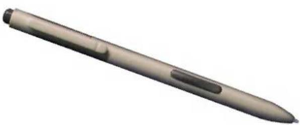
You can use a digitizer pen to control the system. The side button functions as a mouse right button. The top button is the eraser. You can also use the pen to click on the screen and select a file or folder. Double clicking on the screen will act like double clicking a mouse. The pen can be locked in place on the back side of the MICA-101 and needs to be pulled out with fingers for usage.
natural_image
Exterior view of a modern office building (no signage)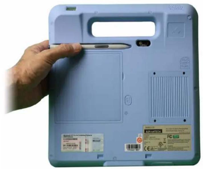
natural_image
Hand holding a blue tablet device with a small electronic device on the cover, showing no visible text or symbols.
natural_image
Hand holding a stylus interacting with the front panel of a blue laptop (no visible text or symbols)3.1.2 Resistive Touchscreen Calibration Function
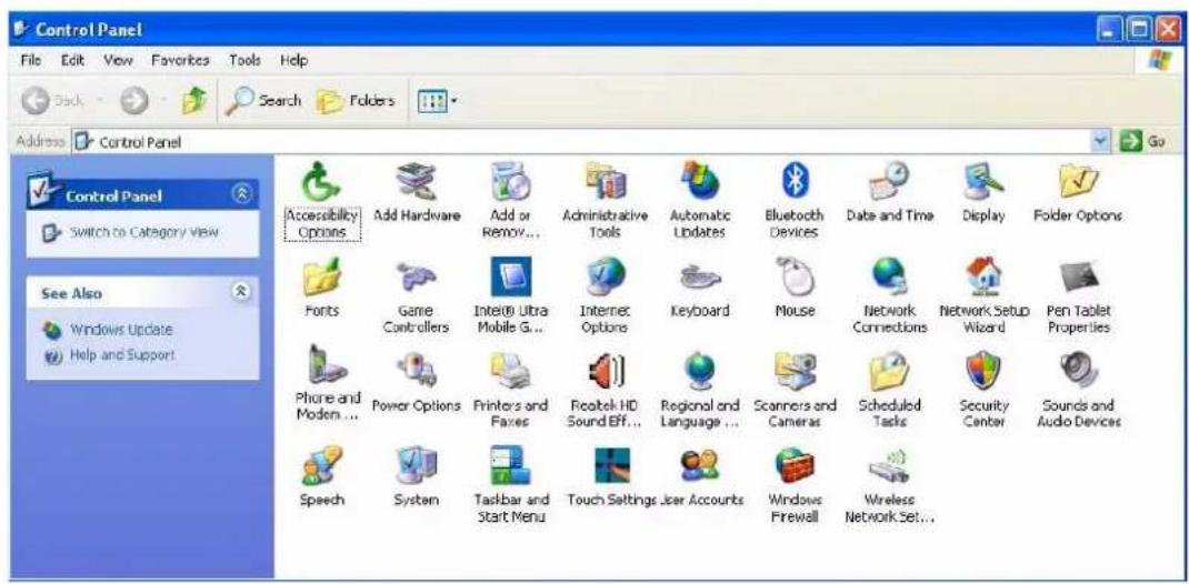
The resistive touchscreen calibration function is found in the control panel. Please press the calibrate button as shown in the image to start the process.


3.1.3 Digitizer Touchscreen Calibration Function
The digitizer touchscreen calibration function is found in the control panel. Please press calibrate button as shown in the image to start the process.
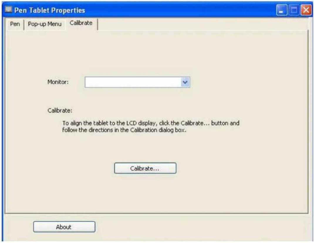
3.1.4 Virtual Keyboard
This is a tool for keyboard input. The tool will be automatically enabled after the system boot up completes.

3.2 RFID Function
The RFID program (MICA-101_RFID) can be enabled when the system is turned on. Note: Please remove the Advantech RFID and Barcode program from startup if the Intel SDK is installed. Follow the instructions below.
- Press RFID button as shown below and an enable message dialog box will be displayed within 2 seconds.

- Place the sensor card behind the upper left-hand corner within 25 mm of the MICA-101. The sensor location is also marked on the back side of the device. When successful, the system will sound a beep.


natural_image
Hand holding a tablet device with a desktop computer displaying a Windows 9.5 interface (no visible text or symbols on the device screen)- The RFID program can output scanned data into any blank text field.
- Pressing the RFID button again will disable the RFID function and a RFID disabled message dialog box will be displayed within 2 seconds.

3.3 Barcode Function
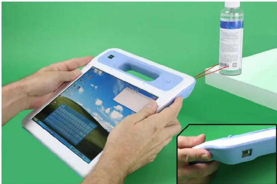
The Barcode program (MICA-101_Barcode) can be enabled when the system is turned on. Note: Please remove the Advantech RFID and Barcode program from startup if the Intel SDK is installed. Please follow the instructions below.
- Press the Barcode button shown below. A sensor light will be illuminated for 3 seconds.
natural_image
Person using a tablet device with a solar farm display, next to a water bottle and a close-up of a handheld device (no visible text or symbols)-
During these 3 seconds, a target can be scanned using the sensor area found on the back side of the device. To improve accuracy, please adjust the distance between target and device until the data has been successfully scanned. When successful the system will sound a beep.
-
The Barcode program can output scanned data into any blank text field.
3.4 WLAN On/Off (P2 Button)
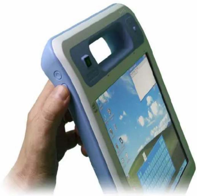
The wireless function default setting is 'On' after system power up. There is an LED status, and a symbol in the system tray to indicate status.
If you would like to disable the WLAN function, press the P2 button and the symbol and LED status will change.
natural_image
Hand holding a smartphone with a green and blue app interface, displaying a map or webpage (no visible text or symbols on the device itself)
3.5 Swap Battery Function (P1 Button)
A feature of the MICA-101 is its battery swap function, which enables more mobility. Press the P1 button and a message will pop up. The swap process must be completed within 10 minutes. Each battery can be swapped out up to 10 times, each time taking no longer than 60 seconds. After this, please plug the unit into the AC adapter for at least 24 hours to charge the internal battery. Additionally, pressing P1 to enter S3 sleep mode will help extend battery life.


3.6 Touchscreen Disable Function
MICA-101 includes both digitizer and resistive touch functions for better control of the system. Pressing the touch lock button as shown below will disable the resistive touch function (the digitizer function remains active). A lock symbol will be displayed in the system tray to indicate a locked status. Press the button again to enable the resistive touch function.



3.7 Camera Function
MICA-101 supports shooting images. Before using this function, enable the embedded program from either the desktop panel (MICA-101_Camera) or by searching in the folder C:\Advantech\MICA-101. Double click the program (MICA-101_CAMAP) and press the Camera button as shown below. An image will be recorded and stored in the folder C:\Advantech\MICA-101.

Chapter 4
Graphics Chipset Setup
4.1 Introduction
The MICA uses an Intel® Poulbso SCH chipset for its graphics controller. Poulsbo is a single-chip system controller hub (SCH) that consists of an integrated graphics controller, memory controller, and I/O controller.
4.2 Installation of Chipset Driver
Complete the following steps to install the chipset driver. Follow the procedures in the flow chart that apply to the operating system that you are using with MICA.
Step 1. Double click the driver file and click next button.

Step 2. Click Yes button for license agreement.

Step 3. Click Next button for installation information.

Step 4. The program will copy relevant files to the system; click Next to perform install.
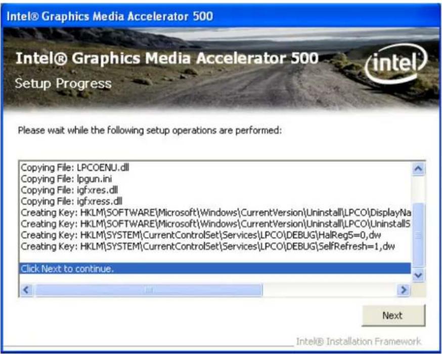
Step 5. Click Finish button to restart system.

Note! The following Windows illustrations are examples only. You must follow the flow chart instructions and pay attention to the instructions which appear on your screen.
4.3 Further Information
For further information about the CHIPSET, VGA installation in your MICA, included driver updates, troubleshooting guides and FAQ lists please visit the following web resources.
Advantech websites: www.advantech.com
Chapter 5
Audio Setup
5.1 Introduction
Complete the following steps to install the Audio driver. Follow the procedures in the flow chart that apply to the operating system that you are using.
5.2 Installation of Audio Driver
Step 1. Double click driver file and click Next button to continue installation.

Step 2. Installation completes; press Finish to restart the system.

Note!
The following Windows illustrations are examples only. You must follow the flow chart instructions and pay attention to the instructions which appear on your screen.

5.3 Further Information
For further information about the Audio installation in your MICA, included driver updates, troubleshooting guides and FAQ lists please visit the following web resources.
Advantech websites: www.advantech.com
Chapter 6
Touchscreen Setup
6.1 Introduction
MICA supports dual-mode with pen and fingertip touch capabilities on screen (touch input priority: pen first and then finger touch). This enables a more intuitive, natural input (pen and touch) and enjoyable user experience
6.2 Installation of Touchscreen Driver
Step 1. Double click driver file and click Accept button to accept license agreement and continue installation.

Step 2. Installation completes; restart the system to finish.
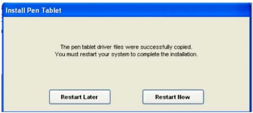
Note! The following Windows illustrations are examples only. You must follow the flow chart instructions and pay attention to the instructions which appear on your screen.
6.3 Further Information
For further information about the touch installation in your MICA, included driver updates, troubleshooting guides and FAQ lists please visit the following web resources.
Advantech websites: www.advantech.com
Chapter 7
Ethernet Driver Installation
7.1 Installation of Ethernet Driver
Step 1. Double click driver file and click Next button to continue installation.

Step 2. Click Finish button to complete installation.
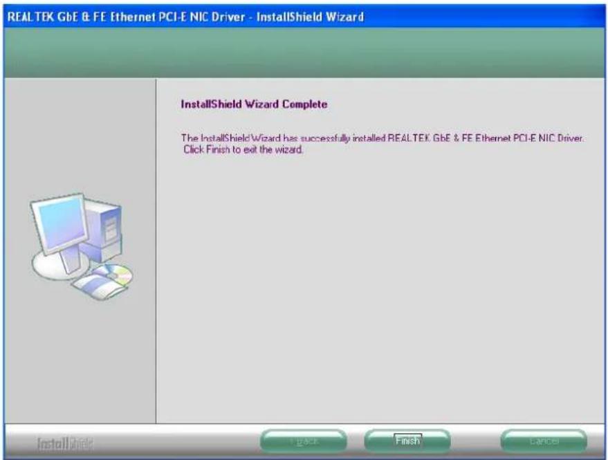
Note! The following Windows illustrations are examples only. You must follow the flow chart instructions and pay attention to the instructions which appear on your screen.
7.2 Further information
For further information about the Ethernet installation in your MICA, included driver updates, troubleshooting guides and FAQ lists please visit the following web resources.
Advantech websites: www.advantech.com
Chapter 8
RFID Driver installation
8.1 Introduction
MICA supports a RFID reader function to help nurses identify patients and verify themselves as authorized caregivers, as well as reducing prescription errors.
8.2 Installation of RFID Driver
Step 1. Double click driver file and click Next button to continue installation.

Step 2. Select a destination folder using the Browse button. The default is C:\Program Files\RFID\USB Driver. Click Next button to continue installation.

Step 3. Click Finish button to complete the installation.
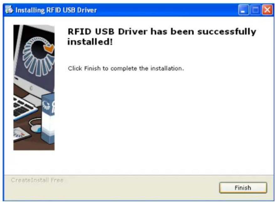
Note! The following Windows illustrations are examples only. You must follow the flow chart instructions and pay attention to the instructions which appear on your screen.
8.3 Further Information
For further information about the RFID installation in your MICA, included driver updates, troubleshooting guides and FAQ lists please visit the following web resources.
Advantech websites: www.advantech.com
Chapter 9
WIFI Driver Installation
9.1 Installation of RFID Driver
Step 1. Double click driver file to choose language and click Next button to continue installation.

Step 2. Click Next button for driver and utilities installation.

Step 3. Click Next button after reading license agreement.
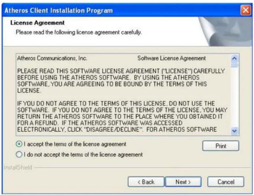
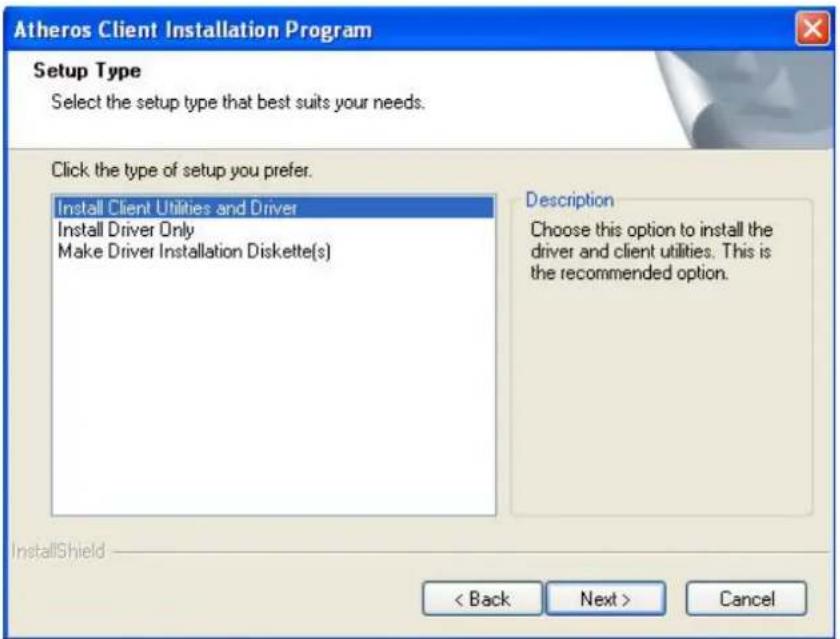
Step 4. Choose install option and click Next button to continue.
Step 5. Select destination folder and click Next button to continue.

Step 6. Select program folder and click Next button to continue.

Step 7. Read the description of the utilities and click Next button to continue.

Step 8. Click Next button to continue installing utilities

Step 9. Click Yes button to continue installation and confirm system reboot.

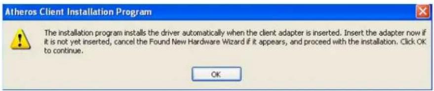
Step 10. Click OK button to continue installation.
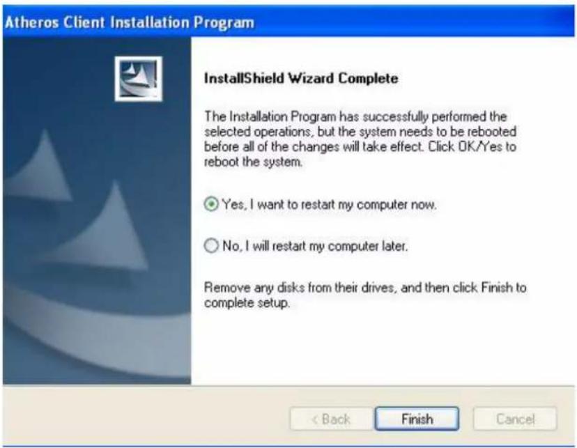
Step 11. When the installation has completed, select Yes to reboot the system.
Note! The following Windows illustrations are examples only. You must follow the flow chart instructions and pay attention to the instructions which appear on your screen.
9.2 Further Information
For further information about the WIFI installation in your MICA, included driver updates, troubleshooting guides and FAQ lists please visit the following web resources.
Advantech websites: www.advantech.com
Chapter 10
Accessories
10.1 Accessory List
10.2 Battery Charger
This battery charger is designed to charge up to 4 battery packs.

natural_image
White plastic mechanical housing with blue internal components, no visible text or symbols10.3 VESA Cradle
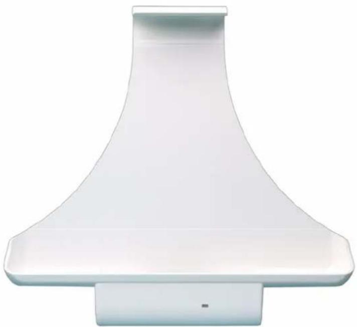
The VESA cradle is designed for wall or cart mounting use.
natural_image
White plastic kitchen chimney with a conical top and base (no text or symbols visible)
Figure 10.1 Cradle Dimensions (Optional)
Table 10.1: Battery Charger
| Item Description | |
| Dimensions (W×D×H) 354 mm x 260 mm x 70 mm | |
| Weight 2000 g | |
| Fast charge slot x 1 Charge time less than 1.5 hrs | |
| Standard charge slot x 3 Charge time less than 4 hrs | |
| LED Indicators | |
| Red Charging | |
| Orange Charging and reaching 90 ~ 99% capacity | |
| Green Complete charge | |
| Environmental Specifications | |
| Operating temperature | 0 ~ 40°C |
| Storage temperature | -20 ~ 70°C |
Table 10.2: VESA Cradle Specifications
| Item Description | |
| Dimensions (W×D×H) 264 mm x 42 mm x 241 mm | |
| Weight 210 g | |
| I/O Ports | USB x 1 |
| LAN x 1 | |
| VGA x 1 | |
| Power-in Jack | |
| LED Indicators | |
| Blue Power Present | |
| Dimensions (W×D×H) 264 mm x 140 mm x 107 mm | |
| Weight 1300 g | |
| I/O Ports Ethernet LAN x 1 | USB x 4 |
| D-SUB VGA x 1 | |
| RS-232 x 1 | |
| Battery charge bay x 1 | |
| Power-in jack x 1 | |
| Card reader for smart card | |
| LED Indicators | |
| Power LED Blue: Power present | |
| Battery charger LED Orange: charging | |
| Black: no battery plug-in | Green: full |
| Smart card reader LED Blue: Power present | |
| Charge time for battery 2.5 to 4 hrs | |
| Environmental specifications | |
| Operating temperature | 0 ~ 40°C |
| Storage temperature | -20 ~ 60°C |
Table 10.3: Full Function Cradle
Table 10.4: Digitizer Pen
| Item Description |
| Dimensions (W×D×H) 12 mm x 10 mm x 140 mm |
| Weight 10 g |
| Side button Right mouse button |
| Rear button Eraser |
Table 10.5: Battery
| Item Description | |
| Dimensions (W×D×H) 112 mm x 14 mm x 113 mm | |
| Weight 300 g | |
| Capacity 3760mAh | |
| Normal voltage 11.1 V | |
| Environment Specifications | |
| Operating charge | 0 ~ 40°C |
| Operating discharge | -20 ~ 60°C |
| Storage temperature | -20 ~ 70°C |
Table 10.6: Carrying Strap
| Item Description |
| Dimensions (W×D×H) 1320 mm |
| Weight 94 g |
10.4 Full Function Cradle
This full function cradle includes: USB ports x4, RS-232 port x1, LAN port out x1, battery charge slot x1 and smart card reader slot x1.

natural_image
3D model of a white plastic electronic component with internal slots and a slot, shown against a solid blue background (no text or symbols)ADVANTECH
www.advantech.com
Please verify specifications before quoting. This guide is intended for reference purposes only.
All product specifications are subject to change without notice.
No part of this publication may be reproduced in any form or by any means, electronic, photocopying, recording or otherwise, without prior written permission of the publisher.
All brand and product names are trademarks or registered trademarks of their respective companies.
© Advantech Co., Ltd. 2009
- Mobile Clinical Assistant (MCA)
- Copyright
- Acknowledgements
- Declaration of Conformity
- FCC Class B
- Packing List
- Additional Information and Assistance
- Warning!
- Safety Instructions
- Caution!
- Medical Equipment
- Contents
- Chapter 1 General Information ....1
- Chapter 2 Getting Started....7
- Chapter 3 Using MICA-101....23
- Chapter 4 Graphics Chipset Setup ...... 35
- Chapter 5 Audio Setup....41
- Chapter 6 Touchscreen Setup...... 45
- Chapter 7 Ethernet Driver Installation ...... 49
- Chapter 8 RFID Driver installation 53
- Chapter 9 WIFI Driver Installation....57
- Chapter 10 Accessories ......63
- Chapter 1
- Introduction
- Specifications
- Touchscreen Specifications
- Cleaning/Disinfecting
- Steps:
- Dimensions
- Chapter 2
- A Quick Tour of MICA
- A Quick Tour of MICA Cradle (Optional)
- Installation Procedures
- Powering MICA by Battery Power
- Installing a Battery
- Connecting the Adapter to MICA
- Connecting the Power Cord for the Cradle
- Connecting the Keyboard and Mouse
- Switching on the Power
- LED Signals
- Bluetooth ON/OFF LED
- RFID ON/OFF LED
- WiFi ON/OFF LED
- Power/Battery Status LED
- MICA Cradle LED Signals
- Power LED
- Lan LED
- Buttons
- Barcode Scanner Button
- Power and P2 button
- Battery Removal Button
- Running the BIOS Setup Program
- Installing System Software
- Installing the Drivers
- Chapter 3
- Power on the System
- Digitizer Pen
- Resistive Touchscreen Calibration Function
- Digitizer Touchscreen Calibration Function
- Virtual Keyboard
- RFID Function
- Barcode Function
- WLAN On/Off (P2 Button)
- Swap Battery Function (P1 Button)
- Touchscreen Disable Function
- Camera Function
- Chapter 4
- Introduction
- Installation of Chipset Driver
- Further Information
- Chapter 5
- Introduction
- Installation of Audio Driver
- Further Information
- Chapter 6
- Touchscreen Setup
- Introduction
- Installation of Touchscreen Driver
- Further Information
- Chapter 7
- Installation of Ethernet Driver
- Further information
- Chapter 8
- Introduction
- Installation of RFID Driver
- Further Information
- Chapter 9
- Installation of RFID Driver
- Further Information
- Chapter 10
- Accessory List
- Battery Charger
- VESA Cradle
- Full Function Cradle
- ADVANTECH
- www.advantech.com
Brand : Advantech
Model : MICA-101
Category : Graphic tablet