
AX-DSPL-VW1 - Audio/video converter Metra - Free user manual and instructions
Find the device manual for free AX-DSPL-VW1 Metra in PDF.


| Product Type | Audio/Video Converter (DSP Interface) |
| Brand | Metra |
| Model | AX-DSPL-VW1 |
| Input Channels | 6 |
| Output Channels | 6 (Front, Rear, Subwoofer) |
| Input Impedance | 1M Ohm |
| Input Voltage (High Level) | 0 - 28V peak-to-peak |
| Input Voltage (Low Level) | 0 - 4.9V peak-to-peak |
| Output Voltage | Up to 5V RMS |
| Output Impedance | 50 Ohms |
| Frequency Response | 20Hz - 20kHz |
| THD | < 0.03% |
| Signal-to-Noise Ratio | 105dB @ 5V RMS |
| Equalizer | 15-Band Graphic EQ, +/-10dB |
| Crossover Filters | Low Pass, Band Pass, High Pass |
| Crossover Slopes | 12dB/24dB/36dB/48dB per octave |
| Delay Adjustment | Up to 10ms per channel |
| Operating Voltage | 10-16V DC |
| Standby Current Draw | 7mA |
| Operation Current Draw | 150mA |
| Remote Output | 12V DC (signal sense or with ignition) |
| Sampling Rate | 48kHz |
| Control | Bluetooth via mobile app (Android/iOS) |
| Updatable | Micro-B USB |
| Applications | Volkswagen (2011-2014, excluding Fender sound system) |
Frequently Asked Questions - AX-DSPL-VW1 Metra
User questions about AX-DSPL-VW1 Metra
0 question about this device. Answer the ones you know or ask your own.
Ask a new question about this device
Download the instructions for your Audio/video converter in PDF format for free! Find your manual AX-DSPL-VW1 - Metra and take your electronic device back in hand. On this page are published all the documents necessary for the use of your device. AX-DSPL-VW1 by Metra.
USER MANUAL AX-DSPL-VW1 Metra
natural_image
Collection of various electronic components and connectors, including a black rectangular device with colored wires and connectors (no visible text or symbols)INTERFACE COMPONENTS
- AXDSPL-VW1 interface
- AXDSPL-VW1 interface harness
- AXDSPL-VW1 vehicle T-harness • Bass knob
APPLICATIONS
Visit axxessinterfaces.com for current application list
Volkswagen † DSP Interface With Pre-Wired Harness 2011-2014
† Excluding models equipped with a Fender sound system
INTERFACE FEATURES
- Includes a DSP (Digital Signal Processor)
• 15 Band graphic EQ - 6 outputs including front, rear, and subwoofer
- Independent equalization for front, rear, and sub
- Selectable low pass, band pass, and high pass filters
- Selectable crossover slopes; 12db, 24db, 36db, 48db
• Each channel can be delayed independently up to 10ms - Clipping detection and limiting circuits
- Designed for non-amplified models
- Easy behind the radio installation with pre-wired harness
- Internal header port for adding interface modules
- Bass knob included for level control of subwoofer amp
- Settings adjusted via Bluetooth @ in a smart device application (tablet or mobile phone), compatible with both Android and Apple devices
- Read, write, and store configurations for future recall
- Password protect feature available in the mobile app
- Micro-B USB updatable
TABLE OF CONTENTS
Installation Options 2
Installation 2
Connections 3-4
AXDSPL-BT Installation....5
AXDSPL-SP Installation....6
Mobile App 7-15
Specifications 16
TOOLS & INSTALLATION ACCESSORIES REQUIRED
- Crimping tool and connectors, or solder gun, solder, and heat shrink • Tape • Wire cutter
- Zip ties • Multimeter
Google Play Store

Apple App Store
iOS 12.1 or higher

INSTALLATION OPTIONS IN STALL AT
Adding a sub to a factory system:
This feature offers the ability to add a subwoofer to a factory system. (refer to page 3)
Adding a full-range amp & sub to a factory system:
This feature offers the ability to add a full-range amp and sub to a factory system. (refer to page 4)
16-pin header port:
Inside the interface is a 16-pin header port for adding optional modules (sold separately). Page 5 and 6 will show the installation and use of these modules.
- AXDSPL-BT - Bluetooth streaming interface
- AXDSPL-SP - Toslink digital output
Note: The interface provides a 12-volt 1-amp output to turn on aftermarket amp(s). If installing multiple amps, an SPDT automotive relay will be required if the amp turn-on current of all amps combined exceeds 1-amp. Use Metra part number E-123 (sold separately) for best results.
N
- Remove the factory radio , then unplug all connectors.
- Install the AXDSPL-VWI vehicle T-harness to the vehicle and make all necessary connections, but leave the amp turn-on wire disconnected.
- Plug the AXDSPL-VW1 vehicle T-harness to the AXDSPL-VW1 interface.
- Plug the AXDSPL-VW1 interface harness to the AXDSPL-VW1 interface.
- Download and install the AX-DSP-X app from the Google Play Store or Apple App Store.
- Cycle the ignition on.
- Open the app then select the Bluetooth Connection tab. Follow the instructions to pair the mobile device to the interface. Refer to page 6 for more information.
- Scroll to the Configuration tab then select the vehicle type. Press the Lock Down button to save the configuration. Refer to page 7 for more information.
- Connect the amp turn-on wire.
- Adjust the settings in the app as desired. Press the Lock Down + button to save any new configurations.
Refer to Metra online for dash disassembly. If Metra makes a dash kit for the vehicle, disassembly will be within those instructions.
‡ Anytime the interface is locked down the key must be cycled off then back on
ADDING A SUB TO A FACTORY SYSTEM

flowchart
graph TD
    A["Factory Radio"] --> B["Factory Radio Harness"]
    A --> C["Interface"]
    A --> D["Vehicle T-Harness"]
    A --> E["Keep Connected"]
    A --> F["Interface Harness"]
    A --> G["Bass Knob"]
    A --> H["Black - Ground Orange - Control"]
    A --> I["RCA Jacks (sold separately)"]
    I --> J["Blue/White - Amp Turn-On Wire"]
    B --> K["Any remaining wires tape off and disregard"]
    C --> L["Any remaining wires tape off and disregard"]
    D --> M["These outputs can be used for additional sub amps, or for adding onto the system at a later date"]
    E --> N["Blue/White - Amp Turn-On Wire"]
REV. 8/3/2020 INSTAXDSPL-VW1
ADDING A FULL-RANGE AMP & SUB TO A FACTORY SYSTEM
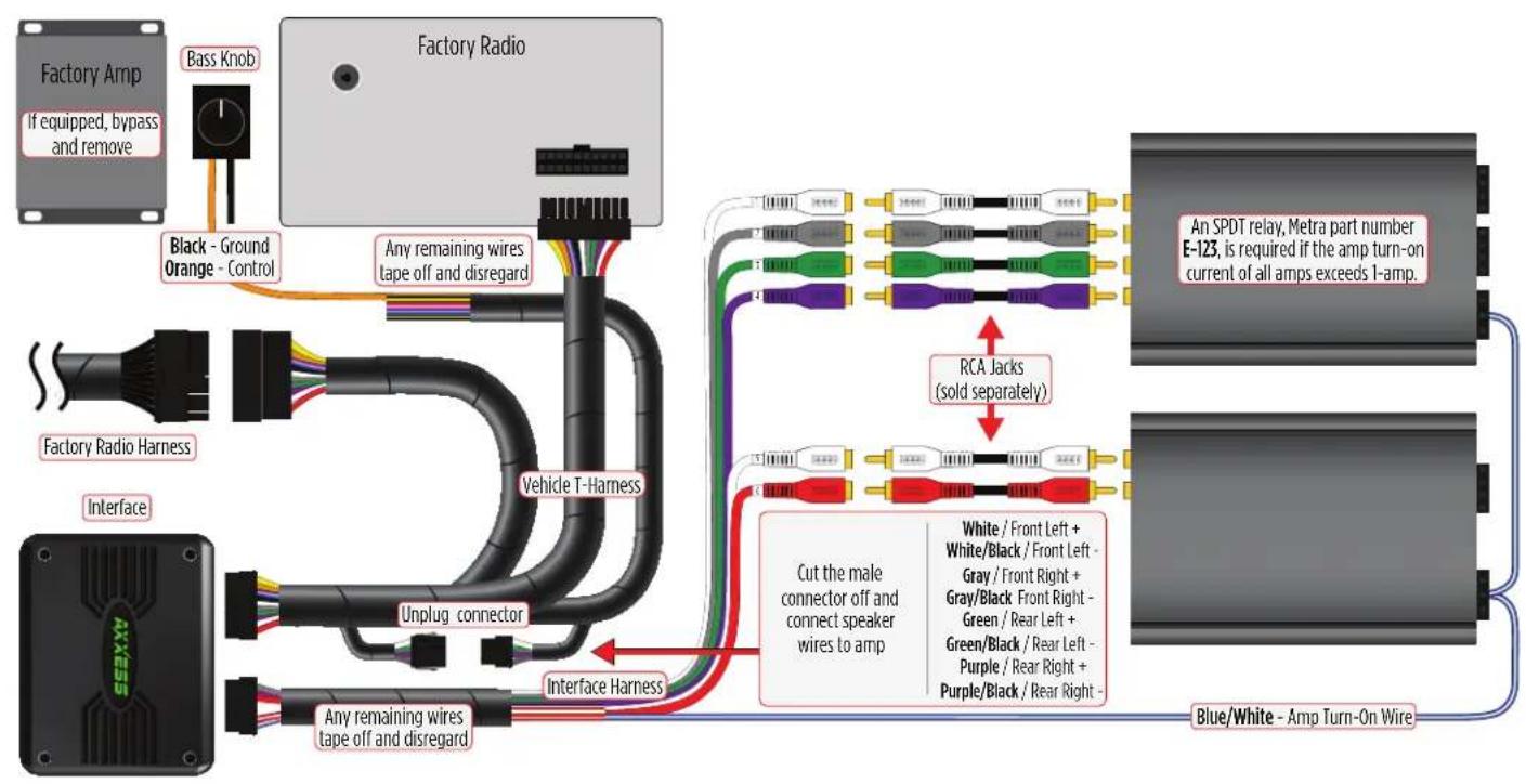
flowchart
graph TD
    A["Factory Amp"] --> B["Bass Knob"]
    B --> C["Factory Radio"]
    C --> D["Black - Ground Orange - Control"]
    C --> E["Any remaining wires tape off and disregard"]
    F["Factory Radio Harness"] --> G["Interface"]
    G --> H["Vehicle T-Harness"]
    H --> I["Unplug connector"]
    I --> J["Interface Harness"]
    K["Blue/White - Amp Turn-On Wire"] --> L["Cut the male connector off and connect speaker wires to amp"]
    M["An SPDT relay, Metra part number E-123, is required if the amp turn-on current of all amps exceeds 1-amp."] --> N["RCA jacks (sold separately)"]
    O["White / Front Left + White/Black / Front Left - Gray / Front Right + Gray/Black Front Right - Green / Rear Left + Green/Black / Rear Left - Purple / Rear Right + Purple/Black / Rear Right - Blue/White - Amp Turn-On Wire"] --> N
    style A fill:#f9f,stroke:#333
    style F fill:#ccf,stroke:#333
    style K fill:#cfc,stroke:#333
BLUETOOTH STREAMING INTERFACE

- The AXDSPL-BT Bluetooth streaming interface can be used to stream media directly to the interface.
- While streaming media the volume on the phone will be used. As an option, the AXBK-1 (sold separately) can be used to control the volume.
Note: The bass knob included with the AXDSPL-VW1 can be used if it will not be used to control a subwoofer.
- Important! Unplug the interface from the vehicle.
- Remove (4) Phillips screws securing the interface, then remove the top cover, exposing the circuit board within.
- Locate the 16-pin header on the circuit board.
- Important! Referencing how the AXDSPL-BT is laid out in the picture, carefully line up the header pins to the interface. Gently press down to secure.
Note: Both interfaces may be damaged if installed wrong.
- Reinstall the top cover to complete the installation.
AXBK-1 Installation:
- Connect the Brown wire from the interface to the Orange wire from the AXBK-1. Ground the Black wire from the AXBK-1.
Continued on the next page
TOSLINK DIGITAL OUTPUT

• The AXDSPL-SP Toslink digital output can be used for adding a digital output to the interface.
- Important! Unplug the interface from the vehicle.
- Remove (4) Phillips screws securing the interface, then remove the top cover, exposing the circuit board within.
- Locate the 16-pin header on the circuit board.
- Important! Carefully line up the header pins to the AXDSPL-SP, with the Toslink port facing outward. Gently press down to secure.
Note: Both interfaces may be damaged if installed wrong.
- Reinstall the top cover provided with the AXDSPL-SP to complete the installation.
MOBILE APP
Setup Instructions

- General information tab for installing the interface.
Continued on the next page
MOBILE APP (CONT.)
Bluetooth Connection

- Scan - Press this button to start the Bluetooth pairing process, then select the interface once it is found. "Connected" will appear in the top left corner of the app once paired.
- Disconnect - Disconnects the interface from the app.
Note: The ignition must be cycled on during this process.
Continued on the next page
MOBILE APP (CONT.)
Configuration

- Identify - Click this button to send a test tone to the front left speaker*.
* Only installations using the front left output (white RCA jack). - Reset to Defaults - Resets the interface to factory settings. During the reset process the amp(s) will shut off for 5-10 seconds.
- Vehicle Type - Select the vehicle type from the drop down box, then click the apply button
- Lock Down - Click this button to save the selected settings.
Attention! This must be done before closing the app or cycling the key otherwise all new changes will be lost!
- Save Configuration - Saves the current configuration to the mobile device.
- Recall Configuration - Recalls a configuration from the mobile device.
- About - Displays information about the app, vehicle, interface, and mobile device.
- Set Password - Assign a 4-digit password to lock the interface. If no password is desired, use "0000". This will clear out any currently set password. It is not necessary to lock down the interface when setting a password.
Note: A 4-digit only password must be chosen otherwise the interface will show "password not valid for this device".
Continued on the next page
MOBILE APP (CONT.)
Outputs

Output Channels
- Location - Location of speaker.
-
Group - Used to join channels together for simple equalization. Example, left front woofer/midrange and left front tweeter will be considered simply left front. The letter M indicates the speaker assigned as the master speaker.
-
Invert - Will invert the phase of the speaker.
- Mute - Will mute desired channel(s) for tuning individual channels.
Continued on the next page
MOBILE APP (CONT.)
Crossover Adjust

- Select the desired crossover filter per channel, low pass, band pass, or high pass.
- Select the desired crossover slope per channel, 12db, 24db, 36db, or 48db.
- Select the desired crossover frequency per channel, 20hz to 20khz.
Note: The front and rear channels default to a 100Hz high pass filter to keep the low frequency signals out. If a subwoofer is not being installed, change the front and rear crossover points down to 20Hz for a full range signal, or to the lowest frequency the speakers will play down to.
Continued on the next page
MOBILE APP (CONT.)
Equalizer Adjust

- All channels can be adjusted independently within this tab with 15 bands of available equalization. It is best to tune this by using an RTA (Real Time Analyzer).
• The Gain slider on the far left is for the channel selected.
Continued on the next page
MOBILE APP (CONT.)
Delay Adjust

- Allows a delay of each channel. If a delay is desired, first measure the distance (in inches) from each speaker to the listening position, then enter those values to the corresponding speaker. Add (in inches) to the desired speaker to delay it.
Continued on the next page
MOBILE APP (CONT.)
Inputs/Levels

- Chime Volume - Not applicable in this application.
-
Clipping Level - Use this feature to protect sensitive speakers like tweeters from being driven past their capabilities. If the output signal of the interface clips the audio will be reduced by 20dB. Turning down the stereo will allow the audio to come back at a normal level. The sensitivity of this feature can be adjusted to the listening preference of the user.
-
Amp Turn On
- Signal Sense - Will turn the amp(s) on when an audio signal is detected, and keep on for 10 seconds after the last signal. This ensures the amp(s) won't shut off between tracks.
- Always On - Will keep the amp(s) on as long as the ignition is cycled on.
- Turn on Delay - Can be used to delay audio output to avoid turn-on pops.
- Subwoofer Input - Select Front + Rear
Continued on the next page
MOBILE APP (CONT.)
Locking Down Data

Last and the most important. You must lock down your configuration and cycle the key!!!

AXDSPL-VW1 INSTALLATION INSTRUCTIONS
SPECIFICATIONS
Input Impedance 1M Ohm
Input Channels 6
Input Options High Level or Low Level
Input Type Differential balanced
Input Voltage 0 - 28-volts (peak-to-peak)
(high level range)
Input Voltage 0 - 4.9-volts (peak-to-peak)
(low level range)
Ouput Channels 6
Output Voltage Up to 5-volts RMS
Output Impedance 50 Ohms
Equalizer Type 15 Band Graphic EQ, +/- 10dB
THD <0.03%
Frequency Response 20Hz - 20kHz
Crossover Filter Low pass, band pass, high pass
Crossover Frequency Selectable 20hz to 20khz
Crossover Slope 12db/24db/36db/48db
Crossover Type Linkwitz-Riley
Sampling 48kHz
S/N Ratio 105dB @ 5-volts RMS
Operating Voltage 10-16 volts DC
Standby Current Draw 7mA
Operation Current Draw 150mA
Adjustments/Controls Application via Bluetooth
Remote Output 12 volts DC (signal sense or with ignition
Having difficulties? We're here to help.

ur Tech Support line at:
386-257-1187

mail at:
techsupport@metra-autosound.com
Tech Support Hours (Eastern Standard Time)
Monday - Friday: 9:00 AM - 7:00 PM
Saturday: 10:00 AM - 7:00 PM
Sunday: 10:00 AM - 4:00 PM

KNOWLEDGE IS POWER
Enhance your installation and fabrication skills by swelling in the most recognized and respected
mobile electronics school in our industry.
Log onto www.installerinstitute.com or call
800-354-6782 for more information and take steps

Metra recommends MECP certified technicians
- INTERFACE COMPONENTS
- APPLICATIONS
- Volkswagen † DSP Interface With Pre-Wired Harness 2011-2014
- INTERFACE FEATURES
- TABLE OF CONTENTS
- TOOLS & INSTALLATION ACCESSORIES REQUIRED
- INSTALLATION OPTIONS IN STALL AT
- Adding a sub to a factory system:
- Adding a full-range amp & sub to a factory system:
- 16-pin header port:
- N
- BLUETOOTH STREAMING INTERFACE
- AXBK-1 Installation:
- TOSLINK DIGITAL OUTPUT
- MOBILE APP
- Setup Instructions
- MOBILE APP (CONT.)
- Bluetooth Connection
- Configuration
- Outputs
- Location Group
- Output Channels
- Crossover Adjust
- Equalizer Adjust
- Delay Adjust
- Inputs/Levels
- Locking Down Data
- AXDSPL-VW1 INSTALLATION INSTRUCTIONS
- SPECIFICATIONS
- Tech Support Hours (Eastern Standard Time)
Brand : Metra
Model : AX-DSPL-VW1
Category : Audio/video converter