
DAC250EB2WDB - Air conditioner DANBY - Free user manual and instructions
Find the device manual for free DAC250EB2WDB DANBY in PDF.


| Product type | Air conditioner |
| Brand | Danby |
| Model | DAC250EB2WDB |
| Cooling capacity | 2 500 BTU/h |
| Maximum recommended area | 25 m² |
| Installation type | Window |
| Dimensions (W x H x D) | 50 cm x 40 cm x 35 cm |
| Net weight | 18 kg |
| Power supply | 220-240 V ~ 50 Hz |
| Power consumption | 750 W |
| Main functions | Cooling, ventilation, dehumidification |
| Number of fan speeds | 3 (Low, Medium, High) |
| Built-in thermostat | Yes, adjustable |
| Programmable timer | 24 hours |
| Remote control | Yes, included |
| Air filter | Washable and reusable |
| Noise level | 52 dB (approx.) |
| Exhaust | Through the window |
| Maintenance | Filter cleaning every 2 weeks |
| Safety | Frost protection, automatic shut-off in case of overheating |
| Spare parts | Available on the manufacturer's website (remote control, filter) |
| Repairability | Repairability index of 6.5/10 (estimated) |
Frequently Asked Questions - DAC250EB2WDB DANBY
User questions about DAC250EB2WDB DANBY
0 question about this device. Answer the ones you know or ask your own.
Ask a new question about this device
Download the instructions for your Air conditioner in PDF format for free! Find your manual DAC250EB2WDB - DANBY and take your electronic device back in hand. On this page are published all the documents necessary for the use of your device. DAC250EB2WDB by DANBY.
USER MANUAL DAC250EB2WDB DANBY
Owner's Manual....1 - 16
AIR CONDITIONER
Welcome to the Danby family. We are proud of our quality products and we believe in dependable service. We suggest that you read this owner's manual before plugging in your new appliance as it contains important operation information, safety information, troubleshooting and maintenance tips to ensure the reliability and longevity of your appliance.
Visit www.Danby.com to access self service tools, FAQs and much more. For additional assistance call 1-800-263-2629.
Note the information below; you will need this information to obtain service under warranty.
You must provide the original purchase receipt to validate your warranty and receive service.
Model Number: ____
Serial Number: ____
Date of Purchase: ____
Need Help?
Before you call for service, here are a few things you can do to help us serve you better.
Read this owner's manual:
It contains instructions to help you use and maintain your appliance properly.
If you receive a damaged appliance:
Immediately contact the retailer or builder that sold you the appliance.
Save time and money:
Check the troubleshooting section at the end of this manual before calling. This section will help you solve common problems that may occur.

1-800-26- Danby
(1-800-263-2629)

Important Safety Information READ AND FOLLOW ALL SAFETY INSTRUCTIONS
ELECTRICAL REQUIREMENTS
All wiring must comply with local and national codes and must be installed by a qualified electrician. Check the available power supply and resolve any wiring problems before installing and operating this appliance.
The rating plate located on the right side of the appliance just above the power cord contains electrical and other technical data.
This appliance is not designed for "through the wall" installation.
GROUNDING INSTRUCTIONS
This appliance must be grounded. Grounding reduces the risk of electrical shock by providing an escape wire for the electrical current.
This appliance has a cord that has a grounding wire with a 3-prong plug. The power cord must be plugged into an outlet that is properly grounded. If the outlet is a 2-prong wall outlet, it must be replaced with a properly grounded 3-prong wall outlet.
WARNING - Improper use of the grounding plug can result in a risk of electric shock. Consult a qualified electrician or service agent if the grounding instructions are not completely understood, or if doubt exists as to whether the appliance is properly grounded.
Do not connect your appliance to extension cords or together with another appliance in the same wall outlet.
Do not splice the power cord. Do not under any circumstances cut or remove the third ground prong from the power cord. Do not use extension cords or ungrounded (two prongs) adapters.
If the power supply cord is damaged, it must be replaced by the manufacturer, its service agent or similar qualified person in order to avoid hazard.
POWER SUPPLY CORD
The power cord contains a device that senses damage to the power cord. To test if the power cord is working properly:
- Connect the power supply cord to an electrical outlet.
- The power supply cord has two buttons located on the head of the plug. One button is marked "Test" and the other is marked "Reset". Press the "Test" button and the "Reset" button will pop out and click.
- Press the "Reset" button and a click will sound as the button engages.
- The power supply cord is now energized and supplying electricity to the appliance.
Notes:
- If the appliance looses power, the reset button may need to be reengaged when the power resumes.
- This button should not be used to turn the appliance on and off.
- The "Reset" button must always be pushed in for correct operation.
- The power supply cord must be replaced if it fails to reset when the "Test" button is pushed in.
POWER RECEPTACLES
These appliances require higher voltage receptacles than standard household receptacles. Consult the table below to find the required receptacle for your model number.
| Model Number Voltage Receptacle | ||
| DAC180EB2WDB | 240 |  |
| DAC250EB2WDB | 240 |  |
SAVE THESE INSTRUCTIONS!
INSTALLATION INSTRUCTIONS
LOCATION
This air conditioner is designed for easy installation in single or double hung windows. Since window designs vary, it may be necessary to make some modifications for safe installation.
This air conditioner is not designed for vertical, slider type windows or "through the wall" installation.
Ensure that the window and frame are structurally sound and free from dry or rotted wood.
Install the air conditioner in a window on a side of the building which favors more shade than sunlight. If the appliance must be in direct sunlight, it is advisable to provide a shade awning over the appliance to ensure efficient functioning.
Do not install the appliance where leakage of combustible gas is suspected.
This appliance is designed to evaporate condensation under normal conditions. Under extremely hot or humid conditions, excess condensation may overflow to the outside. The appliance should be installed where condensation cannot drip on pedestrians or neighboring properties.
Provide sufficient clearance around the appliance to allow ample air circulation. The rear of the appliance should be outdoors, it should not be in a garage or another room. Keep the appliance away from obstacles and at least 76 cm (30 inches) above the ground. Ensure that curtains and other obstructions do not block air flow to the appliance.

REQUIRED TOOLS
- Screwdrivers: Phillips and flat head. • Power Drill: 1/8" (3.2mm) diameter drill bit
- Pencil
- Measuring Tape
- Scissors
- Carpenter's Level
ACCESSORIES
The following accessories are included with the appliance and should be used during the installation.
- 7/16" (11 mm) locking screw and flat washer (x2)
- 1/2" (13 mm) hex-head screw (x7)
- 1/2" (13 mm) screw and locknut (x4)
- 3/4" (19 mm) flat head bolt and locknut (x2)
- 3/4" (19 mm) screw (x2)
- 5/16" (8 mm) hex-head locking screw (x10)
- 1/4" (8 mm) screw (x2)
- Safety lock for wood window frames
- Safety lock for vinyl window frames (x2)
- Sill angle bracket (x2)
- Frame lock (x2)
- Foam insert (x2)
- Window sash foam seal
- Weather stripping (x5)

INSTALLATION INSTRUCTIONS
INSTALLATION
Installation of this appliance will require removing the interior chassis, installing the cabinet in the window, and then replacing the interior chassis in the cabinet. This process is done to minimize possible injury or property damage during installation.
It is recommended to use two people during the installation process.
Removing the chassis from the cabinet
- Open the front panel and remove the air filter, then remove the front panel. Set both the filter and the front panel aside for later use.
- Locate the four screws securing the front face of the appliance.
- Remove the four screws and set them aside for later use.
- Remove the front face of the appliance and set aside for later use.
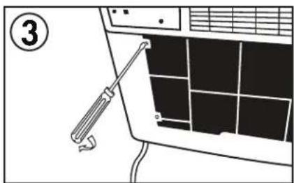
- Remove the shipping screws on top of the cabinet.
- Pull outward on the base handle to remove the chassis from the cabinet.
Note: There may be packaging on the interior chassis. Ensure that it is removed before replacing the chassis in the cabinet.


INSTALLATION INSTRUCTIONS
"L" and "U" Shaped Channel Brackets
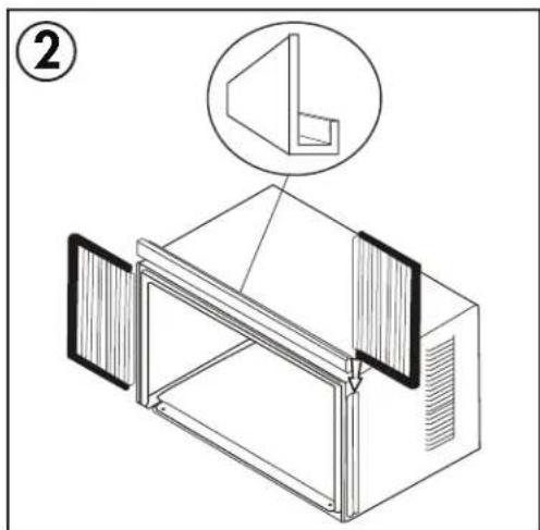
- Attach the foam insert to the top of the cabinet above the screw holes. Install the "L" shaped mounting bracket to the top of the cabinet and the "U" shaped channels to the sides of the cabinet using the 5/16" (8 mm) hex-head screws provided.
- Slide the side curtains into the channels created by the "L" and "U" shaped brackets on both sides of the cabinet.
- Open the window and mark the center of the window sill. Place the cabinet in the window with the lower "U" channel firmly seated over the edge of the window sill. Close the window over the top of the cabinet behind the "L" shaped bracket to hold the cabinet in the window. Shift the cabinet to the left or right as required to line up the center of the cabinet with the center of the window sill. Fasten the cabinet to the window sill using the 3/4" (19 mm) hex-head screws provided.


Check the Tilt Angle
The air conditioner should be tilted downward towards the outside approximately 3° to 4°. This tilt will encourage any condensed water to drain to the outside. If any condensed water leaks to the inside of the house, check the tilt angle and adjust as necessary.
Measure the tilt angle from the front of the cabinet's edge. The difference in height between the front and the back of the appliance, labeled "A" on the image, should be approximately 19 mm - 2.5 cm (3/4 inch - 1 inch).

Support Brackets
- Hold each support bracket flush against the outside of the window sill and attach to the bottom of the cabinet using the 1/2" (13 mm) screws and lock nuts provided but do not fully tighten the screws. Mark the brackets at the top level of the window sill and then remove.
- Assemble the sill anchor brackets to the outside support legs using the 3/4" (19 mm) flat head bolts and lock nuts provided.
- Install the support brackets with the sill anchor brackets attached to the correct hole in the bottom of the cabinet. Tighten all six bolts securely.


Extend the Window Filler Panels
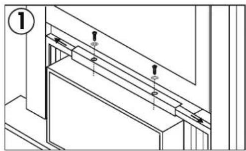
- Raise the window to expose the filler panel locking screws. Loosen the screws so that the filler panels slide easily. Extend the panels to fill the window completely. Use two 7/16" (11 mm) locking screws and flat washers to secure the filler panels and then close the window.
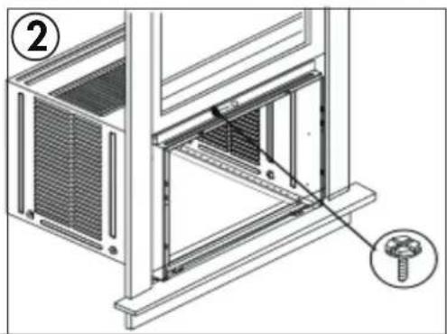
- Secure the cabinet to the top window frame using one 1/2" (13 mm) hex-head screw.
- Secure the window filler panels to the top window sill using two 1/2" (13 mm) hex-head screws. Attach the frame locks to the window sill using two 3/4" (19 mm) screws.
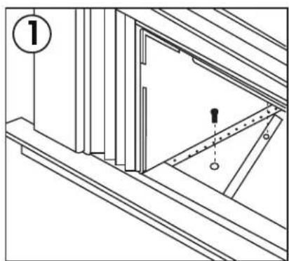
- For vinyl windows, place two safety locks into the holes located in the bottom of the cabinet and secure with two 1/4" (8 mm) screws.

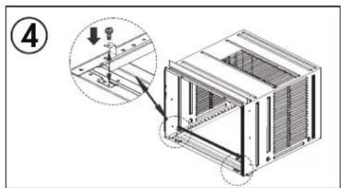
Window Lock and Sash Seal
Place the adhesive foam seal into the opening between the inside and outside windows and attach the safety lock to the outside window frame using two 1/2" (13 mm) screws.

INSTALLATION INSTRUCTIONS
Install the chassis into the cabinet
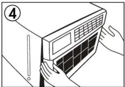
- Carefully slide the chassis into the cabinet. Do not push on the controls or the coils. Ensure that the chassis is firmly seated toward the rear of the cabinet.
- Replace the shipping screws on the top of the cabinet.
- Replace the front face of the appliance.
- Secure the front face of the cabinet with the four screws that were removed earlier.
- Replace the front panel and the air filter.
Note: Do not operate the appliance without the air filter installed.


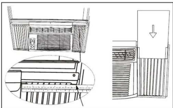
Install the Foam Inserts
The foam inserts can block any cracks or spaces in the side curtains and help maintain the energy efficiency of the appliance.
After the appliance is installed in the window, measure the width of the side curtains from the side of the appliance to the edge of the curtain.
If necessary, cut the foam insert to the correct size and then slide the foam insert into the slots in the side curtain. The supplied weather stripping can be used to block any other cracks or spaces as required.
OPERATING INSTRUCTIONS
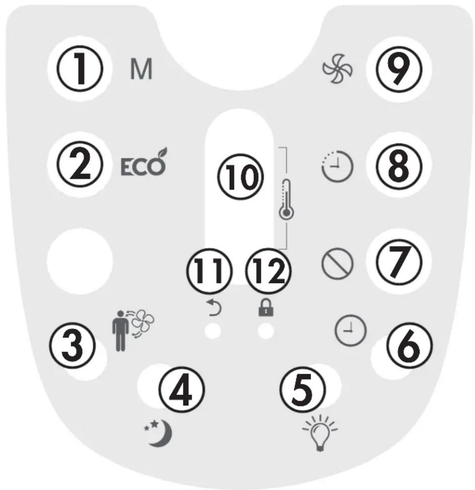
CONTROL PANEL
- Energy Saver Button: Used to set the energy saver function.
- Display Screen and Up and Down Buttons:
- Display screen shows the set temperature, the ambient temperature and the timer settings. To change the temperature scale being displayed, press the up and down buttons at the same time.
- Up and Down Buttons are used to adjust the set temperature and the timer function.
- Sleep Button: Used to set the Sleep function.
- Filter Button: The indicator light will illuminate as a reminder to check the filter. Once the filter has been cleaned, use this button to resume operation.
- Mode Button: Used to choose the operating mode.
- Timer Button: Used to set the auto on and auto off timer.
- Fan Button: Used to set the fan speed. The fan can be set to Low, Medium, High and Auto.
- Follow Me indicator: Light will illuminate to indicate that the Follow Me feature is active.
- Power Button: Used to turn the appliance on or off.
- Remote Control Receiver: Ensure this receiver is not obscured by curtains or other items as it could impact remote control functioning.

OPERATING INSTRUCTIONS
REMOTE CONTROL
- Mode Button: Used to choose the operating mode.
- Energy Saver Button: Used to set the energy saver function.
- Follow Me Button: Used to set the Follow Me function.
- Sleep Button: Used to set the Sleep function.
- LED Button: Press to turn the LED back light on or off.
- Clock Button: Press and hold the button for 3 seconds in order to set the clock. Press the Up and Down Arrows to adjust the time in 10 minute intervals.
Note: The clock feature is only available on the remote, the appliance does not have a clock. The remote clock is a 24 hour clock only.
- Cancel Button: Cancels current Timer settings.
- Timer Button: Used to set the auto on and auto off timer.
- Fan Button: Used to set the fan speed. The fan can be set to Low, Medium, High and Auto.
- Up and Down Arrows: Used to adjust the set temperature and the timer function.
- DefaultButton: Press to restore the remote control default settings.
- Lock Button: Press this button to lock the remote control and prevent the settings from being inadvertently changed.
OPERATING INSTRUCTIONS
REMOTE CONTROL BATTERIES
The remote control requires two AAA alkaline batteries (included). Batteries should be replaced when:
a) No sound is heard when attempting to program the appliance. b) The appliance does not respond to a command issued by the remote control.
Battery replacement:
- Slide the rear cover on the remote in the direction of the arrow.
- Insert two AAA batteries following the same orientation depicted inside the battery chamber (+/-).
- Reinstall the rear cover.
- If the remote control will not be used for extended periods of time, the batteries should be removed.
Notes:
- Protect the remote control from high temperatures, and keep it away from radiation exposure.
- Keep the control panel receiver out of direct sunlight.
- Do not mix old and new batteries.
- Do not mix alkaline, standard (carbon-zinc), or rechargeable (ni-cad, ni-mh, etc) batteries.
- The remote operates within a range of 8 meters (26 ft.) from the receiver located inside the main appliance. Any obstruction between the receiver and remote may cause signal interference, limiting the ability to program the main unit.
This Class B digital apparatus complies with the Canadian ICES-003 standard. CAN ICES-3 (B)
This equipment has been tested and found to comply with the limits for a Class B digital device, pursuant to Part 15 of the FCC Rules. These limits are designed to provide reasonable protection against interference in a residential installation.
This equipment generates, uses and can radiate radio frequency energy and, if not installed and used in accordance with the instructions, may cause interference to radio communications. However, there is no guarantee that interference will not occur in a particular installation.
If this equipment does cause interference to radio or television reception, which can be determined by turning the equipment off and on, the user is encouraged to try to correct the interference by one or more of the following measures:
- Reorient or relocate the receiving antenna.
- Increase the separation between the equipment and receiver.
- Connect the equipment into an outlet on a circuit different from that to which the receiver is connected.
- Consult the dealer or an experienced radio/TV technician for help.
Changes or modifications not approved by the party responsible for FCC compliance could void the user's authority to operate the equipment. This appliance complies with Part 15 of the FCC Rules.
Operation is subject to the following two conditions:
- This device may not cause interference.
- This device must accept any interference received, including interference that may cause undesired operation.
OPERATING INSTRUCTIONS
OPERATING MODES
There are four operating modes to choose from. Press the Mode Button repeatedly to choose the desired mode. The adjacent indicator light will illuminate to show which mode has been selected.
- Cool Mode
Choose cool mode to set the cooling function. Use the up and down arrows to choose the desired temperature. When cool mode is selected, the fan speed can be adjusted by pressing the fan button.
- Dry Mode
Choose dry mode to remove excess moisture from the air during periods of high humidity. All water pulled from the air will condense inside the appliance and drain out the back. The fan speed will be automatically set and cannot be modified in dry mode.
- Fan Mode
Choose fan mode to run the internal fan without engaging the cooling function. Press the fan button repeatedly to choose the fan speed: low, med, high or auto.
- Auto Mode
Auto mode is a pre-set factory program that automatically defines the mode (cool or dry) and fan speed based on the set temperature, the ambient temperature and the ambient humidity.
UP AND DOWN ARROWS
The up and down arrows will modify the set temperature in 1° increments.
The up and down arrows will modify the set time of the timer function in 0.5 hour increments up to 10 hours and then in 1 hour increments up to 24 hours maximum.
TIMER FUNCTION
The Timer Function can be used to turn the appliance on or off after a set period of time.
Auto On Function

- Press the Timer Button once and the Auto On indicator light will illuminate.
- Use the Up and Down Arrows to select the desired amount of time before the appliance should turn on.
- Use the Mode Button to select the desired mode.
- Use the Fan Button to select the desired fan speed.
- The time selected will appear on the display panel and will count down until the appliance turns on.
Auto Off Function

- Press the Timer Button twice and the Auto Off indicator light will illuminate.
- Use the Up and Down Arrows to select the desired amount of time before the appliance should turn off.
- The time selected will appear on the display panel and will count down until the appliance turns off.
Using Auto On and Auto Off Simultaneously
If there is a need for the appliance to turn on, run for a set period of time and then turn off, the Auto On and Auto Off functions can be used at the same time by first setting one and then the other. Both indicator lights will illuminate and the display will count down to the appliance either turning off or on, whichever function was set first.
Note: The timer will not cycle the appliance on and off indefinitely. The Auto On and Auto Off timers will function one time and then the appliance will return to regular functioning.
Turning the appliance off, pressing the default button on the remote or unplugging the appliance will clear all memory settings, including the timer.
OPERATING INSTRUCTIONS
FOLLOW ME FUNCTION
There is a temperature sensor built into the remote control that continuously collects the current room temperature. Keep the remote control with you and the appliance will automatically adjust the set temperature based on the current temperature where you are located to reach the most comfortable condition and temperature.
Press the Follow Me button to activate the Follow Me function. The remote will display the current temperature at its location. The remote will send a signal to the air conditioner every 3 minutes, as long as you remain within range of the appliance.
The Follow Me light on the control panel of the appliance will illuminate for 5 seconds every three minutes to indicate that it has received a signal from the remote. If the appliance does not receive a signal from the remote during any 7 minute interval, it will beep to indicate that the Follow Me mode has ended.
The maximum distance for the Follow Me feature is 8 meters (26 feet). This feature is available in Cool and Auto modes.
SLEEP FUNCTION
The Sleep Function can be used to conserve energy during sleeping hours.
When selected, the set temperature will increase by 1°C / 2°F every half hour for one full hour. The appliance will hold the new set temperature for 6 hours before automatically returning to normal operation.
The Sleep Function can be canceled at any time by pressing the Sleep Button.
ENERGY SAVER FUNCTION
The Energy Saver Function will automatically cycle the fan on and off when the compressor is not in use to minimize how often the compressor needs to turn on. This function is available in Cool, Dry, Auto Cool and Auto Fan modes.
The fan will continue to run for 3 minutes after the compressor turns off. The fan will then cycle on for 2 minutes in 10 minute intervals until the ambient temperature is above the set temperature, at which point the compressor will turn on and cooling will resume.
ADJUSTING AIR FLOW
The louvers on the front of the appliance can be adjusted up and down or left and right to direct air flow throughout the room as required.
Note: When in cooling mode, ensure the louvers are pointed upward. If the appliance operates in cooling mode with the louvers pointed downward for an extended period of time, condensation can form on the louver and drip from the surface of the blades.

CARE & MAINTENANCE
AIR FILTER
The air filter should be cleaned approximately every 2 weeks. The air filter may require more frequent cleaning if there is significant dander or fur in the air.
Approximately every two weeks, the filter indicator light on the control panel will illuminate as a reminder to clean the filter. Follow the steps below to clean the filter and return the appliance to normal functioning.
- The air filter is located behind the front intake grill. To remove the air filter, grasp the filter tab on the right side of the grill and slide it out to the right. If the front intake grill has two indents, pull the grill forward to remove the air filter.
- Use a vacuum cleaner with a soft brush attachment to remove any large debris or dust build up from the air filter.
- Wash the filter in lukewarm, soapy water, below 40° C ( 104° F), or use a neutral cleaning agent.
- Rinse the filter with clean water and dry thoroughly before reinstalling in the appliance.
- Press the filter button on the control panel to resume normal functioning.
Note: Do not operate the appliance without the air filter installed.
ERROR CODES
If the display panel shows any of the below error codes, unplug the appliance, let it stand for 5-10 minutes and then plug it back in. If the error persists, call for service.
AS - Room temperature sensor error
HI - Temperature sensor error
LO - Temperature sensor error
"." - Evaporator temperature sensor error
CLEANING
To avoid possible electric shock, ensure that the appliance is unplugged before performing any cleaning or maintenance.
The outside of the appliance can be wiped clean with a soft cloth or with a lukewarm, damp cloth if necessary.
Do not use gasoline, benzene, thinner or any other chemicals to clean this appliance as these substances can cause damage to the finish and deformation of plastic parts.
Never pour water directly onto the appliance as this will cause deterioration of electrical components and wiring insulation.
END OF SEASON CARE
Before removing the appliance from service for the year, operate the appliance on high fan mode for half a day to ensure the inside of the appliance is dry. This will help avoid the growth of mold or mildew inside the appliance. Ensure the filter is clean and dry. Store the appliance covered in a dry location.
Note: When installing or removing the appliance from the window, ensure that caution is taken to prevent it from falling backward. It is recommended that installation or removal is completed with assistance to prevent injury to persons or damage to property or the appliance.
DISPOSAL
Check for local regulatory compliance regarding approved and safe disposal of this appliance.
TROUBLESHOOTING
Danby Consumer Care: 1-800-263-2629
Hours of operation:
Monday to Thursday 8:30 am - 6:00 pm Eastern Standard Time
Friday 8:30 am - 4:00 pm Eastern Standard Time
Information in this manual is subject to change without notice.
| PROBLEM POSSIBLE CAUSE | |
| Appliance will not operate • Plug is not fully inserted into the wall outlet• Blown fuse or circuit breaker | |
| Insufficient cooling | • Air filter is dirty• Blocked air flow• Appliance size is too small for application |
| Noise • Inadequate support in window installation | |
| Odors • Formation of mold or mildew on internal wet surfaces• Place an algaecide tablet in base pan; push the tablet through the grill on either side of the appliance | |
| Water dripping inside • Appliance is not properly angled to allow water to drain to the outside | |
| Water dripping outside • On very hot or humid days dripping water from the back of the appliance is normal | |
| Frost build up • When outdoor temperature are below 18.3°C (65°F) frost may form when the appliance is in cooling mode• Switch the appliance to fan only mode until the frost melts | |
LIMITED "IN HOME" WARRANTY
This quality product is warranted to be free from manufacturer's defects in material and workmanship, provided that the unit is used under the normal operating conditions intended by the manufacturer.
This warranty is available only to the person to whom the unit was originally sold by Danby Products Limited (Canada) or Danby Products Inc. (U.S.A.) (hereafter "Danby") or by an authorized distributor of Danby, and is non-transferable.
TERMS OF WARRANTY
Plastic parts are warranted for thirty (30) days from the date of purchase, with no extensions provided.
First 12 months During the first twelve (12) months, any functional parts of this product found to be defective, will be repaired or replaced, at warrantor's option, at no charge to the original purchaser.
To obtain service Contact the dealer where the unit was purchased, or contact the nearest authorized Danby service depot, where service must be performed by a qualified service technician. If service is performed on the unit by anyone other than an authorized service depot, all obligations of Danby under this warranty shall be void.
Boundaries of in-home service Danby reserves the right to limit the boundaries of "In Home Service" to the proximity of an authorized service depot. Any appliance requiring service outside the limited boundaries of "In Home Service", will be the consumer's responsibility to transport at their own expense to the original point of purchase or a service depot for repair. If the appliance is installed in a location that is 100 kilometers (62 miles) or more from the nearest service center, it must be delivered to the nearest authorized Danby Service Depot by the purchaser.
Transportation charges to and from the service location are not protected by this warranty and are the responsibility of the purchaser.
Nothing within this warranty shall imply that Danby will be responsible or liable for any spoilage or damage to food or other contents of this appliance, whether due to any defect of the appliance, or its use, whether proper or improper.
EXCLUSIONS
Save as herein provided, by Danby, there are no other warranties, conditions, representations or guarantees, express or implied, made or intended by Danby or its authorized distributors and all other warranties, conditions, representations or guarantees, including any warranties, conditions, representations or guarantees under any Sale of Goods Act or like legislation or statute is hereby expressly excluded. Save as herein provided, Danby shall not be responsible for any damages to persons or property, including the unit itself, howsoever caused or any consequential damages arising from the malfunction of the unit and by the purchase of the unit, the purchaser does hereby agree to indemnify and hold harmless Danby from any claim for damages to persons or property caused by the unit.
GENERAL PROVISIONS
No warranty or insurance herein contained or set out shall apply when damage or repair is caused by any of the following:
1) Power failure. 2) Damage in transit or when moving the appliance. 3) Improper power supply such as low voltage, defective house wiring or inadequate fuses. 4) Accident, alteration, abuse or misuse of the appliance such as inadequate air circulation in the room or abnormal operating conditions (i.e. extremely high or low room temperature). 5) Use for commercial or industrial purposes (i.e. If the appliance is not installed in a domestic residence). 6) Fire, water damage, theft, war, riot, hostility, acts of God such as hurricanes, floods etc. 7) Service calls resulting in customer education. 8) Improper Installation (i.e. Building-in of a free standing appliance or using an appliance outdoors that is not approved for outdoor application, including but not limited to: garages, patios, porches or anywhere that is not properly insulated or climate controlled).
Proof of purchase date will be required for warranty claims; retain bills of sale. In the event that warranty service is required, present the proof of purchase to our authorized service depot.
Warranty Service
In Home
Danby Products Limited
PO Box 1778, Guelph, Ontario, Canada N1H 6Z9
Telephone: (519) 837-0920 FAX: (519) 837-0449
1-800-263-2629
04/17
Danby Products Inc
PO Box 669, Findlay, Ohio, U.S.A. 45840
Telephone: (419) 425-8627 FAX: (419) 425-8629
Welcome
1-800-26-Danby
(1-800-263-2629)




INSTALLATION INSTRUCTIONS

INSTALLATION INSTRUCTIONS
Supports


INSTALLATION INSTRUCTIONS


INSTALLATION INSTRUCTIONS
CARE AND MAINTENANCE
AIR FILTER
PROBLEM POSSIBLE CAUSE
Danby Products Limited
PO Box 1778, Guelph, Ontario, Canada N1H 6Z9
1-800-26- Danby (1-800-263-2629)


Supports


PROBLEM POSSIBLE CAUSE
Danby Products Limited
PO Box 1778, Guelph, Ontario, Canada N1H 6Z9
Telephone: (519) 837-0920 FAX: (519) 837-0449
1-800-263-2629
04/17
Danby Products Inc.
PO Box 669, Findlay, Ohio, U.S.A. 45840
Telephone: (419) 425-8627 FAX: (419) 425-8629
NOTES / REMARQUES / NOTAS:
NOTES / REMARQUES / NOTAS:
MODEL • MODÈLE • MODELO
DAC180EB2WDB
DAC250EB2WDB


- AIR CONDITIONER
- NEED HELP
- READ THIS OWNER'S MANUAL
- IF YOU RECEIVE A DAMAGED APPLIANCE
- SAVE TIME AND MONEY
- IMPORTANT SAFETY INFORMATION READ AND FOLLOW ALL SAFETY INSTRUCTIONS
- ELECTRICAL REQUIREMENTS
- GROUNDING INSTRUCTIONS
- POWER SUPPLY CORD
- NOTES
- POWER RECEPTACLES
- SAVE THESE INSTRUCTIONS
- INSTALLATION INSTRUCTIONS
- LOCATION
- REQUIRED TOOLS
- ACCESSORIES
- INSTALLATION
- REMOVING THE CHASSIS FROM THE CABINET
- L" AND "U" SHAPED CHANNEL BRACKETS
- CHECK THE TILT ANGLE
- SUPPORT BRACKETS
- EXTEND THE WINDOW FILLER PANELS
- WINDOW LOCK AND SASH SEAL
- INSTALL THE CHASSIS INTO THE CABINET
- INSTALL THE FOAM INSERTS
- OPERATING INSTRUCTIONS
- CONTROL PANEL
- REMOTE CONTROL
- REMOTE CONTROL BATTERIES
- BATTERY REPLACEMENT
- OPERATING MODES
- COOL MODE
- DRY MODE
- FAN MODE
- AUTO MODE
- UP AND DOWN ARROWS
- TIMER FUNCTION
- AUTO ON FUNCTION
- AUTO OFF FUNCTION
- USING AUTO ON AND AUTO OFF SIMULTANEOUSLY
- FOLLOW ME FUNCTION
- SLEEP FUNCTION
- ENERGY SAVER FUNCTION
- ADJUSTING AIR FLOW
- CARE & MAINTENANCE
- AIR FILTER
- ERROR CODES
- CLEANING
- END OF SEASON CARE
- DISPOSAL
- TROUBLESHOOTING
- DANBY CONSUMER CARE
- HOURS OF OPERATION
- LIMITED "IN HOME" WARRANTY
- TERMS OF WARRANTY
- EXCLUSIONS
- GENERAL PROVISIONS
- WARRANTY SERVICE
- IN HOME
- WELCOME
- SUPPORTS
- CARE AND MAINTENANCE
- MODEL • MODÈLE • MODELO
Brand : DANBY
Model : DAC250EB2WDB
Category : Air conditioner