Atdec L-PB - Flat Screen Mount

L-PB - Flat Screen Mount Atdec - Free user manual and instructions

Find the device manual for free L-PB Atdec in PDF.

📄 2 pages English EN Download 💬 AI Question 10 questions ⚙️ Specs
Notice Atdec L-PB - page 1
Pick your language and provide your email: we'll send you a specifically translated version.
Product Type Monitor Arm / Flat Screen Support
Brand Atdec
Model L-PB
Max Load Capacity 9 kg (19.5 lb)
VESA Mounting Patterns 75x75 mm and 100x100 mm
Mounting Options Desk clamp or bolt-through
Rotation Range Up to 180° (optional)
Tilt Adjustment -5° to +15°
Swivel Angle ±90°
Screen Orientation 97° clockwise from starting position
Height Adjustment Gas spring (typical)
Cable Management Integrated cable covers
Security System Included (lock mechanism)
Material Steel and aluminum
Color Black
Weight (arm only) Approx. 2.5 kg (5.5 lb)
Warranty 5 years
Cleaning Wipe with damp cloth; do not use harsh chemicals
Safety Do not exceed maximum weight; ensure secure clamping
Spare Parts & Repairability Contact Atdec for replacement parts; not user-serviceable

Frequently Asked Questions - L-PB Atdec

What is the maximum weight capacity of the Atdec L-PB monitor arm?
The Atdec L-PB supports a maximum load of 9 kg (19.5 lb).
Which VESA patterns are compatible with the L-PB?
The arm is compatible with 75x75 mm and 100x100 mm mounting hole patterns.
Can I install the L-PB without drilling?
Yes, the arm includes a desk clamp option that requires no drilling. A bolt-through option is also available for permanent installation.
How do I adjust the tilt of the monitor?
Tilt adjustment is achieved by loosening the tilt pivot bolt, setting the desired angle (typically -5° to +15°), then retightening. Refer to the manual for exact steps.
Does the L-PB include cable management?
Yes, the arm comes with cable covers that can be snapped on to hide and organize cables along the arm.
How do I remove the monitor from the arm?
First, remove the security system if installed. Then, press the release button near the VESA head while gently pulling the monitor upward. The lock button will pop out to indicate release.
What is the maximum rotation of the L-PB?
The arm allows up to 180° rotation (optional) and a fixed 97° clockwise monitor orientation from the starting position.
What warranty does Atdec provide for the L-PB?
Atdec offers a 5-year warranty against manufacturing defects. Contact Atdec support for any issues.
Can I clean the arm with solvents?
No, only use a damp cloth with mild soap if needed. Avoid harsh chemicals as they may damage the finish.
What should I do if the arm does not hold position?
Check that the gas spring tension is adjusted correctly (if applicable) and that all bolts are tightened. Ensure the load does not exceed 9 kg. If the problem persists, contact Atdec support.

User questions about L-PB Atdec

0 question about this device. Answer the ones you know or ask your own.

Ask a new question about this device

The email remains private: it is only used to notify you if someone responds to your question.

No questions yet. Be the first to ask one.

Download the instructions for your Flat Screen Mount in PDF format for free! Find your manual L-PB - Atdec and take your electronic device back in hand. On this page are published all the documents necessary for the use of your device. L-PB by Atdec.

USER MANUAL L-PB Atdec

Step 8. Monitor Orientation

NOTE: the anchor at only one 97° clockwise from the starting position (when facing the correct)

  1. If the monitor up or down to suit the rear

Atdec L-PB - Step 8. Monitor Orientation - 1

Upward/ Downward Tilt Portrait/ Landscape Rotation

INSTALLATION COMPLETE - Refer to the User Exercise Guide for your adjustments

How to remove the Monitor

  1. All you installed the Security System in Step 5, remove it
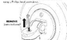
Atdec L-PB - How to remove the Monitor - 1

  1. All you highlighted the most common in law 2, known as the case is not present using the law file key were led.

Atdec L-PB - How to remove the Monitor - 2

  1. Unlock the Chuck Breas coupling in a known below, and it is likely necessary for my own side.

LIFT Mounting Head Gold Sensor Coupling TO UNLOCK Price in BLACK Inner Segment

NOTE: When you press in the hand near button, the white one button will open out to indicate the lock has been discharged.

How to remove Cable Covers
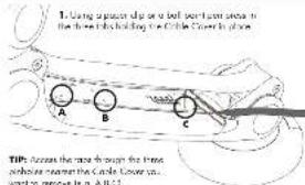
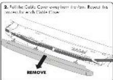
1. Using a particle tip or a ball sheet into a hole in the three bodies holding the Cable Cover in place A B C TIPS: Access the mode through the frame. pulse tube is formed that the Cable Cover is ward to remove it in A,B,C

Atdec L-PB - How to remove Cable Covers - 2

Atdec L-PB - How to remove Cable Covers - 3

Aquestration of the carbon monoxide is involved in a bioreactor with an aldehyde and a water-silicate mixture of the E_2 -fluorobenzene and ethylbenzene. The reaction involves the addition of water-silicate (Pd) and 32.0% yield.

L-PB

L-PW

Installation Instructions

levitate

Desk | Single

Component Checklist

Arm Assembly with preprocessor Dock Clamp Mounting Head Tools Required: Flights Head, Seaweeding water drill, saw Part Drill Coole Doors (2 part) Box Hole

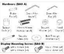
Hardware (BAO-A) Brake Pin (p1) Smart Alpin Seg (p1) 2mm Allo- Key (p1) Secure Bath (p1) 3mm/4mm Barb (p1) & Work Secure Wash (p1) Ilead Cap (p1) Secure Tens (p1) Bolt Through Steep (p1) Display Mounting Screws (BAO-B) 64 x 15mm (p4) 64 x 15mm (p4) Max x 1mm (p4) Max x 2mm (p4)

IMPORTANT INFORMATION

I IMPORTANT - Install Levithate Single Monitor Arm as per Installation Instructions

The product supports a maximum weight of 9kg, 19.5 lb.

The product supports "ESV mounting hole configurant" 75 x 75mm and 100 x 100mm.

The manufacture accepts no responsibility for incorrect installation.

Step 1. Check Components

Check you more selected all parts against the Component Checklist and Human

Step 2. Fealen Bays to Work Surface - Choose DESK CLAMP OR BOLT THROUGH option

(PTO...)

A - DESK CLAMP

The cultural base set up under 360° of

romation of the Lower Arm around the beac.

I you want to find the lower Amr welter to

180° go to A, i not due to F2.

A1. OPTIONAL 180° ROTATION

[...] the loss of an operator to 100% over

the Bcke Pin ordemeth the Deck Camp

1.2

(2) 31

1

1

  1. 2017年1月1日

PUSH

Incril

2023

(1)

(二)

(1) 12 (2) 12 (3)

Disk Clamp

2mm Alw

14

图 1-2

  1. 2017年1月1日

(五)

Remove and re-insert for Desk Clamp, a rope

the S7-10 Allen Key supplied. The go to A2.

A2. Post on Am Ensemble on the work

surface ve hirt in Desk Clamp -argus

the eggs.

m - 1 0 ;

(1)

(2)

(3)

(1) AD = BD = 1

m - 1 0 ;

  1. 2017年1月1日

(1)

( ) Deal.

Clamp

S APQ = S AQP + S_ QPQ

Clamp Pad

  1. Uwarko kong (dek Kow, jiro)

  2. 17: 9 in the "with a."

s-does. I often say from

(二) 2017年1月1日

2.3.1.2.3.4.5.6.7.8.9.10.11.12.13.14.15.16.17.18.19.20.21.22.23.24.25.26.27.28.29.30.31.32.33.34.35.36.37.38.39.40.41.42.43.44.45.46.47.48.49.50.51.52.53.54.55.56.57.58.59.60.61.62.63.64.65.66.67.68.69.70.71.72.73.74.75.76.77.78.79.80.81.82.83.84.85.86.87.88.89.90.91.92.93.94.95.96.97.98.99.100

The Curry Red will automatically

where it follows

(1) 本说明仅供参考。

[Non-Text]

NOTE: the project leading Dark Clamp of our project installation proposal

atrical "tiring to part" occurs to the underside of the work surface

A4. Dark Clean a new printed piece tilt to Semi 3° Optical

B - BOLT THROUGH B1. Remove the Deck Clamp and the 2mm Alax Key wrapped REMOVE (###) (###) Push Alax Key Deck Clamp The default bar setup allows 300° of motion of the lower arm around the nose. If you want to limit the lower Arm position to 180° go a B2, no dot is to B3. B2. OPTIONAL 150° ROTATION B3. Hand the Base Plate to reduce the Deck Clamp. No other required. B4. Roll on frame 2/3 holds from the work surface where you enter the work of the base to be. NOTE: The base are set up at least 25mm (2.17) beam one work was wide edge to allow the diameter of the base. B5. Set up a symmetric length bar, 45mm in 26mm spending on the work surface thickness. SHORT [45mm] saw work surface thickness between 14.25mm x 0.5" x 1. LONO (60mm) saw work surface thickness between 29.0mm x 0.5" x 1. OR Use 1.2 or 3.6 through 5mm on a piece of a beam length of 1mm minimum to 3mm maximum of 30.17 mm priming about the work surface. TIP: Iron work is above thickness from Chow's 7.7", longer than 80 beets can be purchased from hardware above. BA: Align the wire of the base over the profile of the base, fill the bottom wire on B2 laser the base for the work above. TIGHTEN FIRALLY tledded Salt Through Wearer 45mm or Almax hit 3mm Alax Key

Step 3. Tighten Tension Bolts 1. U/L is supported the original for Upper Arm and Lower Arm. Upper Arm Tension Bol Lower Arm Tension Bol 2. Using the 5 ms After Key supplied, I'm the Upper Arm and Lower Arm. Tension Bolts, and the Lower Arm. Support a more weight. LESS TENSION with greater impact MORE TENSION with greater impact

Step 4. Attach Mounting Head to Monitor To Send appropriate Display Mounting Sums from hardware (BAS) or travel the monitor, and autothe Mounting Head to its back or the monitor. TOP OF MONITOR Mounting Head Screening Hole Display Mounting Sums (a) Recessed Mounting Holes or Display with a Curved Rear Panel Display Mounting Sums (b) Spacer Stack (c) Mounting Hole If the Mounting Hole is removed, the back of the monitor, or the monitor has a curved rear panel, use the Sums. It uses a curved rear panel to lock the Mounting Hole. 2. Push the Door Frame over the Mounting Hole. Press firmly around its mode edge will you bear a "COLD" PUSH/PUSH Cover Hole

Step 3. Attach Monitor onto Arm Assembly 1. Open and locate the Mounting-hand arm for the Queue Balance Control. MOVERING HEAD PUSH Quick Forward Couching TO LOCK Press at WHITE Gauge button 2. Once the Mounting Head is at seat, press on the WHITE Gauge button is lock in place, after a "CLICK" NOTE: to unlock and remove the mode, order to transform on the final page. 3. If measure the wire tension to increase head stability. Use the 2mm Alon key applied. 4. Choose SECURITY SCREW OF HEAD CAP motion. SECURITY SCREW Secure Screw Leakery Washer MORE TENSION DO NOT OVERTIGHTEN TIPS When Isolating, the Security Washer moves, but the finger side is forward the mode, so then is low the contact of the Mounting head. HEAD CAP PUSH Head Cap LESS TENSION to be ordered. TIPS When Isolating, the Head Cap moves that the letter side is forward the mode, so then it moves the contact of the Mounting head.

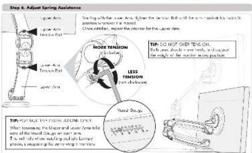
Step b. Adjust Spring Assistance Up Arm Upper Arm Lower Arm Tension Arm Down Arm Tension Arm Down Arm More TENSION Pulsed Less TENSION Pulsed TIP: SO HOT OVER TENS ON. Both same double bolt ends, and upping the angle of the stator's main position. TIP: POT MAT THE INSTAL ADDITIONS ONLY. When tensioning the Ucker and Lower Time take one of the Wound (Laps or other arms). This will also allow making mechanical leisure process to keep the same weight movements.

Step 7. Cable Management How do I continue Cable Connect! Ecuine route for hold 1. To follow the menu ready for MAXIMUM REACH OF COMPACT over depulsed ground, or to reach the menu. MAXIMUM REACH COMPACT 2. Elevator cable along the length of the arm Automated and connected to the motor. TIP: Elevator encroachment is on the sides to above full increment but the side. TIP: T cells progs are too big to 11 through the side, mode it is reduced on the side. 3. Push elevator uncrer remains up on the upper and lower arms to be the elevator in position. 4. Insert Cable & Camera on both sides of the Upper and lower arms. A B C PUSH PUSH NOTE: The Cable Connect is different for lift and right sides.

Manual assistant
Powered by Anthropic
Waiting for your message
Product information

Brand : Atdec

Model : L-PB

Category : Flat Screen Mount