
MA-AGLK-07 - Support mural pour écran tactile AMX - Free user manual and instructions
Find the device manual for free MA-AGLK-07 AMX in PDF.


| Product Type | Uncategorized Electronic Device |
| Brand | AMX |
| Model | MA-AGLK-07 |
| Dimensions (Approx.) | 200 x 150 x 50 mm |
| Weight (Approx.) | 0.5 kg |
| Power Supply | 12V DC, 1A |
| Power Consumption | 5W |
| Main Functions | Signal processing, control interface, connectivity hub |
| Input Ports | 2x HDMI, 1x USB, 1x RS-232 |
| Output Ports | 1x HDMI, 1x Ethernet, 1x IR emitter |
| Compatibility | AMX control systems, third-party AV equipment |
| Mounting | Rack-mountable (1U) or surface mount |
| Operating Temperature | 0°C to 40°C |
| Humidity Range | 10% to 90% non-condensing |
| Maintenance | Keep dry and dust-free; clean with a soft cloth |
| Safety | Use only provided power adapter; avoid liquid contact |
| Spare Parts & Repairability | Contact AMX support for replacement parts; user-replaceable power supply |
| General Information | Designed for professional AV installations; firmware upgradeable |
Frequently Asked Questions - MA-AGLK-07 AMX
User questions about MA-AGLK-07 AMX
0 question about this device. Answer the ones you know or ask your own.
Ask a new question about this device
Download the instructions for your Support mural pour écran tactile in PDF format for free! Find your manual MA-AGLK-07 - AMX and take your electronic device back in hand. On this page are published all the documents necessary for the use of your device. MA-AGLK-07 by AMX.
USER MANUAL MA-AGLK-07 AMX
MA-AGLK-07 Angle Mount Kits
The MA-AGLK-07 Angle Mount Kits (FIG. 1) are designed to mount Modero G5 Series Wall Mount Touch Panels and AMX RoomBook Scheduling Panels (7") into standard sized single and double gang boxes in the US, EU, UK and Australia. Please note the AMK2 Any Mount Kit may be shown in images, but procedure is the same for the angle mount.

FIG. 1 MA-AGLK-07
Models Available/Panel Compatibility
The Angle Mount Kit is available to accommodate 7" Modero G5 Series (wall mount, landscape), 7" Modero S Series, AMX Acendo Book and AMX RoomBook Series Scheduling Touch Panels:
MODELS AVAILABLE / PANEL COMPATIBILITY
| Angle Mount Kit | For use with: |
| MA-AGLK-07 (FG2265-35) | MD-702 (FG5969-55BL): 7" Modero G5 Series Landscape Wall Mount Touch PanelMSD-701-L2 (FG2265-32): 7" Modero S Series Landscape Wall Mount Touch PanelACB-2107 (FG4221-07): 7" AMX Acendo Book Scheduling Touch PanelRMBK-701 (FG2265-37): 7" AMX RoomBook Scheduling Touch Panel |
"AGLK" Angle Mount Kits
The MA-AGLK2-07 Angle Mount Kits are intended for use with Modero G5 touch panels, as well as second-generation “L2” Modero S Series (Landscape/Wall Mount), and AMX Acendo Book & AMX RoomBook Scheduling touch panels. They conveniently place the touch panel at a 15° upward angle for easy readability, ideal for mounting at a lower height to comply with many ADA requirements.
Please note these cannot be used upside down to create a 15° downward angle mount.
Product Specifications
| PRODUCT SPECIFICATIONS | |
| Dimensions HWD: | MA-AGLK-07: 3.97" x 6.74" x 1.76" (100.84 mm x 171.20 mm x 44.70 mm) |
| Weight: | MA-AGLK-07: 0.1 lbs (45.36 g) |
| Included Accessories: | Back Box (5107643-00)Gasket, Foam (66-2265-29)Screw, M3.5 X 30mm, PFH, Clear Zinc (4) (80-1620-04)Screw, #6-32 X 1.25, PFH, Type F, Clear Zinc (4) (80-1700-09) |
Installation of the Angle Mount Kit
The Angle Mount Kits are designed to utilize existing or newly installed gang boxes, with a new back box to replace the back box included with the touch panel. To install an Angle Mount Kit and its accompanying touch panel:
-
Before starting the installation, ensure that Ethernet cable has been pulled to the gang box, and that all appropriate Power Over Ethernet (PoE) injectors have been connected to the cable going to the gang box.
-
If the gang box already has an existing fixture or device installed in it, remove the fixture or device to expose the gang box (FIG. 2).

FIG. 2 EXISTING GANG BOX
- Pull the Ethernet cable into the gang box, making sure that the male RJ-45 connector is accessible within the gang box.
-
Match the screw connector holes on the gang box with the holes in the back box (FIG. 3).
-
The Any Mount Kit back box has multiple holes to allow for single or double gang box design, and for standard gang box designs from the US, UK, EU and Australia.
- Examine how the back box rests on the gang box - look for gaps between the back box and the wall surface.

FIG. 3 TESTING THE ALIGNMENT OF THE BACK BOX SCREW HOLES.
- If the gap between the wall and the back box is excessive, or if the installation of the back box exposes too much of the gang box, you may apply the optional foam gasket (66-2265-29) to the back of the back box. Peel the adhesive backing off the gasket and carefully apply it to the back box surface (FIG. 4).
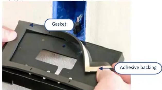
FIG. 4 APPLYING THE OPTIONAL FOAM GASKET TO THE BACK BOX.
- Once the proper mounting position of the back box is confirmed, attach the back box to the gang box, using either the screws used with the original fixture or device or with the included screws in the Angle Mount Kit (FIG. 5).
WARNING: Be careful not to over-tighten the screws - this can bow or damage the back box.
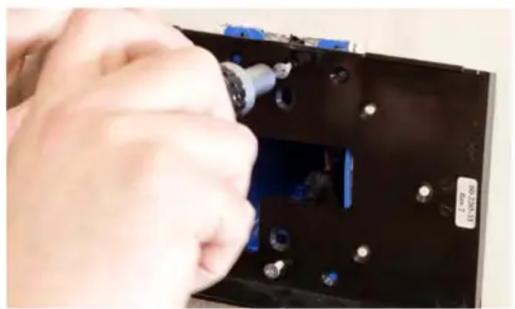
FIG. 5 INSTALLING THE BACK BOX TO THE GANG BOX.
- After installing the back box, inspect the back box's placement.
Note: If necessary, the back box can be removed and the foam gasket installed.
- Pull enough slack on the Ethernet cable through the back box to allow the cable to reach the touch panel's RJ45 connector (FIG. 6).

FIG. 6 ACCESSING THE ETHERNET CABLE THROUGH THE BACK BOX.
- Remove the touch panel's back box to access the back of the panel.
- Insert each connector into its corresponding location along the back of the touch panel. Note: For more information on connections, please refer to the Installation Hardware Reference Manual for the panel being installed, available from www.amx.com.
- Test the incoming wiring by attaching the panel connections to their terminal locations and applying power. Note: Verify that the panel is receiving power and functioning properly to prevent repetition of the installation.
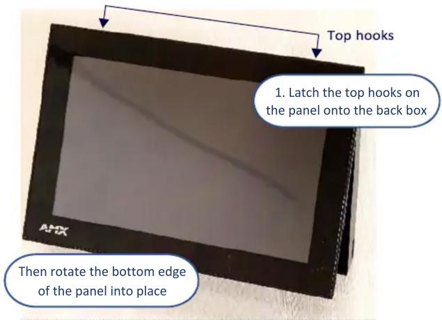
- Latch the panel onto the top hooks on the back box and rotate it down (FIG. 7).
- Press gently and evenly on the surface of the touch panel until the panel locks into place (FIG. 8).
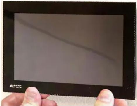
FIG. 8 LOCKING DOWN THE BOTTOM OF THE TOUCH PANEL ONTO THE BACK BOX.
WARNING: if you see a gap between the panel and the back box, or feel any binding while locking down the panel, stop immediately and verify that no cables or other items are in the way. Do not force the panel into position, as this can cause damage to the touch screen or the panel electronics.
Removing the Touch Panel
In order to access the back of the touch panel, such as to install a USB connection for firmware upgrades, the device may need to be removed from the back box. To remove the touch panel:
- From the bottom, pull gently outward from the back box. Gently rock the panel back and forth to free the bottom from the back box.
- Rotate it up to release the top latch hooks, and carefully pull the device free from the back box. Take care not to damage or pull the connections on the back of the device, or to pull the back box from the gang box.
Additional Documentation
The following related product documents are available to view/download at www.amx.com:
- For information on installing Modero G5 Series Touch Panels, refer to the Installation Hardware Reference Manual – Modero G5 Series.
• Specification drawings of the MA-AGLK-07 Angle Mount Kits.

© 2020 Harman. All rights reserved. Modero, Modero G5 Series, AMX, AV FOR AN IT WORLD, HARMAN, and their respective logos are registered trademarks of HARMAN. Oracle, Java and any other company or brand name referenced may be trademarks/registered trademarks of their respective companies.
AMX does not assume responsibility for errors or omissions. AMX also reserves the right to alter specifications without prior notice at any time. The AMX Warranty and Return Policy and related documents can be viewed/downloaded at www.amx.com.
3000 RESEARCH DRIVE, RICHARDSON, TX 75082 | AMX.com | 800.222.0193 | 469.624.8000 | +1.469.624.7400 | fax 469.624.7153
AMX (UK) LTD, AMX by HARMAN - Unit C, Auster Road, Clifton Moor, York, YO30 4GD United Kingdom | +44 1904-343-100 | www.amx.com/eu/
5108277-00 REV: A
Last Revised: 2020-12-04
Brand : AMX
Model : MA-AGLK-07
Category : Support mural pour écran tactile