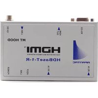
HDBT-1-R - HDMI Extender Apantac - Free user manual and instructions
Find the device manual for free HDBT-1-R Apantac in PDF.


| Product Type | HDBaseT Receiver |
| Model | HDBT-1-R |
| Brand | Apantac |
| Video Support | Up to 4K@60Hz 4:4:4 |
| Audio Support | PCM, Dolby Digital, DTS |
| Transmission Distance | Up to 100m (1080p) / 70m (4K) |
| Connectors | 1x RJ45 (HDBaseT In), 1x HDMI Out, 1x IR Extender, 1x RS-232 |
| Power Supply | DC 12V 1A |
| Power Consumption | 5W (max) |
| Dimensions (W x D x H) | 100mm x 65mm x 25mm |
| Weight | 0.2 kg |
| Mounting | Desktop or Wall-mountable (bracket included) |
| HDCP Support | HDCP 2.2 |
| EDID Management | Built-in EDID emulation |
| IR Control | IR pass-through via extender |
| RS-232 Control | Bidirectional RS-232 pass-through |
| Operating Temperature | 0°C to 50°C |
| Storage Temperature | -20°C to 70°C |
| Compliance | CE, FCC, RoHS |
| Accessories Included | Power adapter, IR extender, mounting bracket, user manual |
Frequently Asked Questions - HDBT-1-R Apantac
User questions about HDBT-1-R Apantac
0 question about this device. Answer the ones you know or ask your own.
Ask a new question about this device
Download the instructions for your HDMI Extender in PDF format for free! Find your manual HDBT-1-R - Apantac and take your electronic device back in hand. On this page are published all the documents necessary for the use of your device. HDBT-1-R by Apantac.
USER MANUAL HDBT-1-R Apantac
natural_image
Front panel of a network device showing ports and connectors (no text or symbols visible)- DC 12 V Input w/ Locking
- LINK OUT (RJ45)
- HDMI Input
- RS232 Input
HDBT-1-E REAR VIEW

- IR Output
- HDCP Indicator
- LINK Indicator
- POWER Indicator
HDBT-1-R FRONT VIEW

- DC 12 V Input w/ Locking
- LINK IN (RJ45)
- HDMI Output
- RS232 Output
HDBT-1-R REAR VIEW
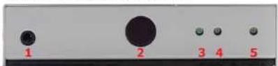
- IR Input
- IR Input
- HDCP Indicator
- LINK Indicator
- POWER Indicator
Specifications
| FEATURES/ MODEL | HDBT-1-E | HDBT-1-R |
| HDMI In 1 x HDMI A-Type Female | None | |
| HDMI Out 1 x HDMI A- | Type Female | |
| RJ-45 1 1 | ||
| IR OUT 3.5 mm phone jack | None | |
| IR IN | None | 3.5 mm phone jack |
| Max Resolution | 1080p 60Hz | 1080p 60Hz |
| Cable Distance | 100 meters (Max) | 100 meters (Max) |
| Power Adapter | 12 V DC | 12 V DC |
| Weight g) | 310g | 310g |
| Dimension (mm) | 150 W x 80 x D 25 H | 150 W x 80 x D 25 H |

© 2012 APANTAC LLC, All rights reserved
7556 SW BRIDGEPORT ROAD
PORTLAND, OR 97224, USA
PHONE +1 503 968 3000
FAX +1 503 389 7921
The content of this document is provided in connection with Apantac LLC ("Apantac") products. Apantac makes no representation or warranties with respect to the accuracy or completeness of the contents of this publication and reserves the right to make changes to specifications and product descriptions at any time without notice.

natural_image
Abstract geometric design with blue dot pattern and partial text 'APANTAC' at bottom (no readable document text or symbols)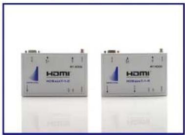
HDBT-SET-1
USER MANUAL
HDMI Extender/Receiver
based on
HDBaseT Technology
Package Contents
1 x HDBT-1-E
1 x HDBT-1-R
User Manual
2 x Power Adapters (12V)
1 x IR Blaster Cable
1 x IR Receiver Cable
Magnetic Mounting Plate
Mounting Screws
Accessories
Power Adapter
IR Receiver Cable
IR Blaster Cable
Mounting Screws
Features
Uses the latest HDBase-T technology
Extends 1080p signals up to 330 feet
(100 meters) with a single CATx cable
Supports HDMI 1.4 with 3D function
Supports HDMI 1.2 and 1.3a
HDCP Compliant
Supports 3D pass-through
Supports CEC pass-through
Supports RS-232 (Bi-directional transfer)
Supports al frequency band IR control
Installation
- Turn off the source (ex: DVD Players) and the HDTV monitor.
- Connect the HDMI cable between the source and the
port of the HDBT-1-E. - Connect the HDMI cable between the HDBT-1-R between the monitor and the
port of the HDBT-1-R. - Connect the CATx cable between the HDBT-1-E and HDBT-1-R's port.
- Connect the power.
IR Receiver Cable
Insert the IR receiver cable into the HDBT-1-R's
GND
+V
3 y
IR Blaster Cable
Insert IR blaster cable into HDMI-1-E
Locate it close to the IR receiving sensor on the source (ex: DVD player).
NC
N
CATx Wiring
| Identification | Pin Assignment | Color Code |
| Pair 1 | 5 White-Blue | |
| 4 Blue | ||
| Pair 2 | 1 White-Orange | |
| 2 Orange | ||
| Pair 3 | 3 White-Green | |
| 6 Green | ||
| Pair 4 | 7 White-Brown | |
| 8 Brown |
| Pin # | Signal | Pin # | Signal |
| 1 | TMDS Data 2+ | 11 | TMDS Clock Shield |
| 2 | TMDS Data 2 Shield | 12 | TMDS Clock - |
| 3 | TMDS Data 2- | 13 | CEC |
| 4 | TMDS Data 1+ | 14 | Reserved(N.C. on device) |
| 5 | TMDS Data 1 Shield | 15 | SCL |
| 6 | TMDS Data 1- | 16 | SDA |
| 7 | TMDS Data 0+ | 17 | DDC/CEC Ground |
| 8 | TMDS Data 0 Shield | 18 | +5 Power |
| 9 | TMDS Data 0- | 19 | Hot Plug Detect |
| 10 | TMDS Clock+ |
Brand : Apantac
Model : HDBT-1-R
Category : HDMI Extender