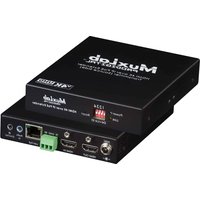
500759-TX-HLO - Audio/video converter MuxLab - Free user manual and instructions
Find the device manual for free 500759-TX-HLO MuxLab in PDF.


| Product Type | HDMI over IP PoE Transmitter with Loop Out |
| Model | 500759-TX-HLO |
| Brand | MuxLab |
| Video Resolution Support | Up to 4K @ 30Hz (4:4:4) and 4K @ 60Hz (4:2:0); 1080p @ 60Hz |
| Max Transmission Distance (Cat5e/6) | 330 ft (100 m) up to 4K @ 30Hz |
| HDMI Input | 1 x HDMI Type A |
| HDMI Loop Out | 1 x HDMI Type A |
| Network Interface | 1 x RJ45 (Cat5e/6) |
| IR Control | 1 x 3.5mm stereo jack for IR emitter; 1 x 3.5mm mono jack for IR receiver (sold separately) |
| RS232 | 1 x 3-pin Phoenix connector |
| Audio Insert | 1 x 3.5mm jack |
| DIP Switches | 4 switches for device ID addressing |
| Compression | JPG2000 Proprietary |
| Bandwidth | Up to 850 Mbps |
| Latency | Typical 1 frame (16 ms), max 2 frames (33 ms) |
| Power Supply | PoE (PD) IEEE 802.3af; optional external 5VDC/2.6A (model 500993) |
| Power Consumption | 2.85W |
| Operating Temperature | 0° to 40°C |
| Storage Temperature | -20° to 85°C |
| Humidity | Up to 95% non-condensing |
| Dimensions (W x D x H) | 4.40" x 5.08" x 1.00" (112mm x 129mm x 25mm) |
| Weight | 1.5 lbs (0.68 kg) |
| Regulatory Compliance | FCC, CE, RoHS |
| Flammability Rating | 94V0 |
| Warranty | 3 years |
| Maintenance | Keep clean and dry; avoid dust; no user-serviceable parts inside |
| Spare Parts / Repairability | Contact MuxLab for replacement or repair; optional accessories available separately |
Frequently Asked Questions - 500759-TX-HLO MuxLab
User questions about 500759-TX-HLO MuxLab
0 question about this device. Answer the ones you know or ask your own.
Ask a new question about this device
Download the instructions for your Audio/video converter in PDF format for free! Find your manual 500759-TX-HLO - MuxLab and take your electronic device back in hand. On this page are published all the documents necessary for the use of your device. 500759-TX-HLO by MuxLab.
USER MANUAL 500759-TX-HLO MuxLab
| Environment | HDMI 2.0b |
| Devices | Blu-Ray, projectors, monitors, TV, PC, laptops, servers supporting HDMI |
| Transmission | Transparent to the user. |
| Bandwidth | 300MHz |
| Signals | HDMI 1.4 protocol |
| Connectors | One (1) HDMI receptacle for input.One (1) HDMI loop out.One (1) RJ45S for Cat 5e/6 unshielded or shielded twisted pair.One (1) 3.5mm jack for IR emitter.One (1) 3.5mm jack for audio insert.One (1) RS232 (3-pin phoenix connector).Four (4) DIP Switches for device ID addressing. |
| Note: Cables not included. | |
| Maximum DistanceBased on a maximum length of 6.6f (2m) of HDMI cable per end. | Cat5e/6: 330f (100m) up to 4K @ 30Hz (4:4:4) and 4K @ 60Hz (4:2:0)Note: When installed in an electrically noisy environment, an STP cable must be used. Also, cross-connection reduces the effective distance depending on the grade of twisted cable used. |
| Latency | Typical one (1) Frame (16ms), maximum 2 frames (33ms). |
| Compression | JPG2000 Proprietary Compression. |
| Bandwidth | Up to 850Mbps. |
| Network Requirement | 1Gb Ethernet Network(Switch support for Jumbo Frame, IGMP and PoE required). |
| IR Frequency | 38 to 56 KHz (IR Emitter and IR Sensor sold separately). |
| RJ45 Pin ConfigurationReverse Polarity Sensitive.Use EIA/TIA 568A or 5868 straight through wiring. | RJ45 LinkPin 1 (R) Pin 2 (T)Pin 3 (R) Pin 6 (T)Pin 4 (R) Pin 5 (T)Pin 7 (R) Pin 8 (T)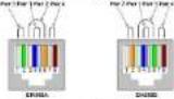 |
| Cable | One (1) Cat 5e/6 or better twisted pair cables required. |
| Power Supply | This device supports PoE (PD), an external power supply is not included. It is intended to be powered via a PoE (PSE) Ethernet Switch. If required, an optiona power supply (500993) may be purchased separately. |
| PoE | IEEE 802.3af |
| Power Consumption | Transmitter: 2.85Watt |
| Temperature | Operating: 0° to 40°C Storage: -20° to 85°C Humidity: Up to 95% non-condensing |
| Dimensions | 4.40" x 5.08" x 1.00"(112mm x 129mm x 25mm) |
| Weight | 1.5lbs (0.68kg) |
| Compliance | Regulatory: FCC, CF, RoIS Flammability: 94V0 |
| Warranty | 3 years |
| Order Information | 500759-TX-HLO HDMI over IP PoE TX with Loop Out, UHD-4K(UPC: 627699927595) |
| Accessories(These items are sold separately) | 500920 16-Port Rackmount Transceiver Chassis500917 Wall Mount Transceiver Bracket Kit500990 IR Limiter500991 IR Sensor500993 Univ. Locking Power Supply 5VDC/2.6A US/UK/EU Blade |
MuxLab
PRODIGITAL
2321Ruc Cohen, Montreal, Quebec, Canada. H4R 2N7
Tel: (514) 905-0588 Fax: (514) 905-0589
Toll Free (North America): (877) 689-5228
E-mail: info@muxlab.com URL: www.muxlab.com
© MuxLab Inc. 94-000985-A SE-000985-A

HDMI over IP PoE TX with Loop Out, UHD-4K
500759-TX-HLO
Quick Installation Guide
Overview
The HDMI over IP PoE TX with Loop Out, UHD-4K (model 500759-TX-HLO) allows HDMI video equipment supporting up to 4K @ 30Hz or 1080p @ 60Hz resolution to be connected and extended to create an independently distributed video network. 100's of Single Displays and Video Wall Displays of user configurable size (X by Y) may be supported, depending on network bandwidth. In addition, the unit features a local HDMI video output which allows the video source to be shown on a local display.
The unit can be connected via Cat5c/6 cable up to 330ft (100m) from an Ethernet Switch, and supports PoE (PD) when powered by a PoE (PSE) Ethernet Switch. An IR Emitter or IR Sensor, if required, may be purchased separately for IR based remote control applications of end devices.
The MuxLab Pro Digital Network Controller (500812) and MuxControl App are available to simplify configuration and management of this and other MuxLab AV over IP networked devices via PC (500812 web interface), Smartphone and Tablet (Apple or Android).
Applications
Applications include video wall, digital signage, commercial and residential AV systems, classroom projector systems, boardroom systems, collaborative PC systems, and medical information systems.
Installation
- Identify the connectors on the Transmitter as indicated on the product labels, see the above front and rear product views for further details.
- Verify that the distance between the HDMI Transmitter is within MuxLab specifications (see Specifications table for more details).
- To install the Transmitter:
3a. Connect the Transmitter to the HDMI video source with an HDMI compliant cable.
3b. If the application is point-to-point, then connect one (1) length of Cat 5c/6 (or higher) grade UTP cable to the RJ45 LINK connector on the Transmitter. If transmitting over the network, use an Ethernet Switch between Transmitter and Receiver
3c. If necessary, connect the Transmitter HDMI Out to a local display with an HDMI compliant cable.
- To install the Receiver (such as the 500759-RX):
4a. Connect the Receiver to the destination HDMI display with an HDMI compliant cable.
4b. If the application is point-to-point, then connect one (1) Cat 5c/6 cable (or higher) coming from the Transmitter to the RJ45 LINK connector on the Receiver. If transmitting over the network, use an Ethernet Switch between Transmitter and Receiver.
- If the configuration is a point-to-multipoint or multipoint-to-multipoint:
5a. You will need to use an Ethernet Switch with Gigabit ports and DHCP Server support. In addition, Jumbo Frame support is required, and IGMP Protocol support is required for the multipoint-to-multipoint case. Verify that the Ethernet Switch is configured correctly and that the DHCP Server, IGMP Protocol, and Jumbo Frames are enabled. See the manufacturer operating manual for more information about configuring the Ethernet Switch.
5b. Connect all Transmitters and Receivers to the Ethernet Switch.
5c. Use the DIP Switches to select a unique Device ID for each Transmitter present on the network and configure each Receiver Device ID to the corresponding selected Transmitter. Note: This step is not necessary if the MuxLab Pro Digital Network Controller (500812) is used.
- Powering the Transmitter or Receiver via an external power supply is only necessary where PoE (PSE) is unavailable. If PoE is unavailable, connect the 5 VDC power supply (sold separately, model 500993) to each Receiver and to an AC power outlet. Next connect each Transmitter in the same manner. If power is present, the green power LED on each Transmitter and Receiver will illuminate.
Note: Power 'ON' the HDMI over IP PoF TX with Loop Out only after all connections have been made.
-
Power 'ON' the HDMI equipment and verify the image quality.
-
This product supports IR pass-thru control. If infrared remote control is needed to control the Source equipment from the Display, connect the IR Sensor (sold separately, model 500991) to the 3.5mm Stereo Jack of the Receiver and the IR Emitter (sold separately, model 500990) to the 3.5mm Mono Jack of the Transmitter.
Note: You can differentiate the IR Sensor and the IR Emitter by looking at the 3.5 mm plug. The IR Sensor is using a Stereo Plug (3 Contacts) and the IR Emitter a mono plug (2 Contacts).
-
Position the IR Sensor so that it is directed at the hand-held remote control. For a clear IR signal reception, aim the hand-held remote control at the top of the IR Sensor enclosure.
-
Position the IR Emitter as close as possible to the source's IR Sensor (i.e. DVD player). For a clear IR signal reception, the IR Emitter can be glued on the source's IR Sensor. The IR Emitter's signal is transmitted from the side of the enclosure.
-
This product supports RS232 bidirectional communication. On the Transmitter, the RS232 port is configured as a DCE; and on the Receiver as a DTE. Please connect your RS232 cable accordingly. Configure the RS232 communications setting via the device web interface.
-
Commands or messages may be sent via RS232 by connecting a PC to the RS232 port of the HDMI over IP PoE Extender, or over the network via IP. This communication is meant to be machine to machine.
-
The following diagram illustrates a typical application.
![graph TD A["Radio"] --> B["Satellite Cable"] B --> C["VR/VR12"] C --> D["VR/VR24"] D --> E["VR/VR36"] E --> F["VR/VR48"] F --> G["VR/VR50"] G --> H["VR/VR62"] H --> I["VR/VR74"] I --> J["VR/VR86"] J --> K["VR/VR90"] K --> L["VR/VR102"] L --> M["VR/VR114"] M --> N["VR/VR126"] N --> O["VR/VR138"] O --…](/content/2026/05/1077747/images/94e566950897b17313e5ec10d5e3abc9775e193d4ebeac3ef63d3187e4e60bf1.jpg)
Troubleshooting
The following table describes some of the symptoms, probable causes and possible solutions in regard to the installation of the HDMI over IP PoE TX with Loop Out, UID-4K:
| Symptom | Transmitter LEDs | Receiver LEDs | Probable Cause | Possible Solutions | ||
| Power | Link | Power | Link | |||
| No Image | OFF | OFF | OFF | OFF | No power | Check power connectionsCheck PoE Ethernet Switch Setup |
| No Image | BLINK | OFF | BLINK | ON | Booting | Wait until booting process finish |
| No Image | ON | OFF | ON | OFF | No Ethernet Link | Check Ethernet Switch StatusCheck UTP Cables |
| Info Screen | ON | OFF | ON | BLINK | UTP Cable | Check the Transmitter UTP cable |
| Info Screen | ON | ON | ON | OFF | UTP Cable | Check the Receiver UTP cable. |
| Info Screen | ON | BLINK | ON | BLINK | No Data Connection | Check if DIP Switch settings match |
| Info Screen | ON | ON | ON | BLINK | Wrong setting on Decoder | Check DIP Switch address of the Receiver |
| Choppy Video | ON | ON | ON | ON | Configuration | Check cable lengthCheck the HDMI Cable QualityCheck if Jumbo Frame and IGMP are enabled on the Ethernet Switch |
| Image flickers when powering up nearby equipment | ON | ON | ON | ON | Interference | Use STP cables |
| IR not functioning * | ON | ON | ON | ON | Interference from sunlight, Fluorescent, Neon or Halogen lights. | Place the IR equipment away for the interfering light |
| IR not functioning † | ON | ON | ON | ON | Interference from RF radiation from the TV | Place the IR equipment away for the RF radiation |
* IR Emitter and IR Sensor sold separately.
If you still cannot diagnose the problem, please call MuxLab Customer Technical Support at 877-689-5228 (toll-free in North America) or (+1) 514-905-0588 (International).
Brand : MuxLab
Model : 500759-TX-HLO
Category : Audio/video converter