
VTO6421F - Video Intercom Dahua Technology - Free user manual and instructions
Find the device manual for free VTO6421F Dahua Technology in PDF.


| Product Type | Video Intercom Door Station |
| Brand | Dahua Technology |
| Model | VTO6421F |
| Dimensions | 140 x 80 x 30 mm |
| Weight | 200 g |
| Power Supply | DC 12V, 1A |
| Camera Resolution | 2 MP (1920 x 1080) |
| Field of View | 120° wide angle |
| Night Vision | IR LED, up to 5 m |
| Audio | Two-way audio with echo cancellation |
| Connectivity | RJ45 Ethernet (PoE optional) |
| Weatherproof Rating | IP65 |
| Mounting Type | Flush mount |
| Material | Aluminum alloy front panel |
| Operating Temperature | -30°C to +60°C |
| Warranty | 2 years |
| Included Accessories | Mounting bracket, screws, quick start guide |
| Key Features | Remote unlock, motion detection, visitor call |
Frequently Asked Questions - VTO6421F Dahua Technology
User questions about VTO6421F Dahua Technology
0 question about this device. Answer the ones you know or ask your own.
Ask a new question about this device
Download the instructions for your Video Intercom in PDF format for free! Find your manual VTO6421F - Dahua Technology and take your electronic device back in hand. On this page are published all the documents necessary for the use of your device. VTO6421F by Dahua Technology.
USER MANUAL VTO6421F Dahua Technology
Model F VTO VTO6441F/VTO6421F
Quick Start Guide
V1.0.1
Cybersecurity Recommendations
Mandatory actions to be taken towards cybersecurity
1. Change Passwords and Use Strong Passwords:
The number one reason systems get "hacked" is due to having weak or default passwords. It is recommended to change default passwords immediately and choose a strong password whenever possible. A strong password should be made up of at least 8 characters and a combination of special characters, numbers, and upper and lower case letters.
2. Update Firmware
As is standard procedure in the tech-industry, we recommend keeping NVR, DVR, and IP camera firmware up-to-date to ensure the system is current with the latest security patches and fixes.
"Nice to have" recommendations to improve your network security
1. Change Passwords Regularly
Regularly change the credentials to your devices to help ensure that only authorized users are able to access the system.
2. Change Default HTTP and TCP Ports:
- Change default HTTP and TCP ports for systems. These are the two ports used to communicate and to view video feeds remotely.
- These ports can be changed to any set of numbers between 1025-65535. Avoiding the default ports reduces the risk of outsiders being able to guess which ports you are using.
3. Enable HTTPS/SSL:
Set up an SSL Certificate to enable HTTPS. This will encrypt all communication between your devices and recorder.
4. Enable IP Filter:
Enabling your IP filter will prevent everyone, except those with specified IP addresses, from accessing the system.
5. Change ONVIF Password:
On older IP Camera firmware, the ONVIF password does not change when you change the system's credentials. You will need to either update the camera's firmware to the latest revision or manually change the ONVIF password.
6. Forward Only Ports You Need:
- Only forward the HTTP and TCP ports that you need to use. Do not forward a huge range of numbers to the device. Do not DMZ the device's IP address.
- You do not need to forward any ports for individual cameras if they are all connected to a recorder on site; just the NVR is needed.
7. Disable Auto-Login on SmartPSS:
Those using SmartPSS to view their system and on a computer that is used by multiple people should disable auto-login. This adds a layer of security to prevent users without the appropriate credentials from accessing the system.
8. Use a Different Username and Password for SmartPSS:
In the event that your social media, bank, email, etc. account is compromised, you would not want someone collecting those passwords and trying them out on your video surveillance system. Using a different username and password for your security system will make it more difficult for someone to guess their way into your system.
9. Limit Features of Guest Accounts:
If your system is set up for multiple users, ensure that each user only has rights to features and functions they need to use to perform their job.
10. UPnP:
- UPnP will automatically try to forward ports in your router or modem. Normally this would be a good thing. However, if your system automatically forwards the ports and you leave the credentials defaulted, you may end up with unwanted visitors.
- If you manually forwarded the HTTP and TCP ports in your router/modem, this feature should be turned off regardless. Disabling UPnP is recommended when the function is not used in real applications.
11. SNMP:
Disable SNMP if you are not using it. If you are using SNMP, you should do so only temporarily, for tracing and testing purposes only.
12. Multicast:
Multicast is used to share video streams between two recorders. Currently there are no known issues involving Multicast, but if you are not using this feature, deactivation can enhance your network security.
13. Check the Log:
If you suspect that someone has gained unauthorized access to your system, you can check the system log. The system log will show you which IP addresses were used to login to your system and what was accessed.
14. Physically Lock Down the Device:
Ideally, you want to prevent any unauthorized physical access to your system. The best way to achieve this is to install the recorder in a lockbox, locking server rack, or in a room that is behind a lock and key.
15. Connect IP Cameras to the PoE Ports on the Back of an NVR:
Cameras connected to the PoE ports on the back of an NVR are isolated from the outside world and cannot be accessed directly.
16. Isolate NVR and IP Camera Network
The network your NVR and IP camera resides on should not be the same network as your public computer network. This will prevent any visitors or unwanted guests from getting access to the same network the security system needs in order to function properly.
General
This Guide introduces the structure, mounting process, and basic configuration of the device.
Safety Instructions
The following categorized signal words with defined meaning might appear in the Guide.
| Signal Words | Meaning |
 | Indicates a medium or low potential hazard which, if not avoided, could result in slight or moderate injury. |
 | Indicates a potential risk which, if not avoided, could result in property damage, data loss, lower performance, or unpredictable result. |
 | Provides additional information as the emphasis and supplement to the text. |
About the Guide
- The Guide is for reference only. If there is inconsistency between the Guide and the actual product, the actual product shall prevail.
• We are not liable for any loss caused by the operations that do not comply with the Guide. - The Guide would be updated according to the latest laws and regulations of related regions. For detailed information, see the paper manual, CD-ROM, QR code or our official website. If there is inconsistency between paper manual and the electronic version, the electronic version shall prevail.
- All the designs and software are subject to change without prior written notice. The product updates might cause some differences between the actual product and the Guide. Please contact the customer service for the latest program and supplementary documentation.
- There still might be deviation in technical data, functions and operations description, or errors in print. If there is any doubt or dispute, please refer to our final explanation.
- Upgrade the reader software or try other mainstream reader software if the Guide (in PDF format) cannot be opened.
- All trademarks, registered trademarks and the company names in the Guide are the properties of their respective owners.
- Please visit our website, contact the supplier or customer service if there is any problem occurred when using the device.
- If there is any uncertainty or controversy, please refer to our final explanation.
Important Safeguards and Warnings
The following description is the correct application method of the device. Please read the manual carefully before use, in order to prevent danger and property loss. Strictly conform to the manual during application and keep it properly after reading.
Operating Requirement
- Please don't place and install the device in an area exposed to direct sunlight or near heat generating device.
- Please don't install the device in a humid, dusty or fuliginous area.
- Please keep its horizontal installation, or install it at stable places, and prevent it from falling.
- Please don't drip or splash liquids onto the device; don't put on the device anything filled with liquids, in order to prevent liquids from flowing into the device.
- Please install the device at well-ventilated places; don't block its ventilation opening.
- Use the device only within rated input and output range.
- Please don't dismantle the device arbitrarily.
- Please transport, use and store the device within allowed humidity and temperature range.
Power Requirement
- The product shall use electric wires (power wires) recommended by this area, which shall be used within its rated specification!
- Please use power supply that meets SELV (safety extra low voltage) requirements, and supply power with rated voltage that conforms to Limited Power Source in IEC60950-1. For specific power supply requirements, please refer to device labels.
- Appliance coupler is a disconnecting device. During normal use, please keep an angle that facilitates operation.
Table of Contents
Cybersecurity Recommendations....I
Foreword IV
Important Safeguards and Warnings ...... V
1 Appearance .... 1
1.1 Dimension ...... 1
1.2 Front Panel.... 2
1.3 Rear Panel 3
2 Installation....5
2.1 Installation Requirement .... 5
2.1.1 Notice....5
2.1.2 Guidance....5
2.2 Connecting Cable 5
2.2.1 Door Lock Port 5
2.2.2 RS-485 Port 7
2.2.3 Alarm I/O and Power Port 7
2.2.4 Wiegand Port 7
2.3 Installing VTO....9
3 Configuration.... 11
3.1 Configuration Process....11
3.2 Config Tool 11
3.3 Configuring VTO 11
3.3.1 Initialization....11
3.3.2 Configuring VTO Number 12
3.3.3 Configuring Network Parameters 13
3.3.4 Configuring SIP Server 14
3.3.5 Adding VTO Devices....15
3.3.6 Adding Room Number 16
3.4 Verifying Configuration....18
3.4.1 Calling VTH from VTO 18
3.4.2 Doing Monitor from VTH....18
4 Operating VTO 20
4.1 Call Function 20
4.1.1 Calling single VTH....20
4.1.2 Calling Multiple VTH Devices 20
4.1.3 Calling Management Center.... 20
4.2 Unlock Function 20
4.2.1 Unlock with Face Recognition 20
4.2.2 Unlock with Password 20
4.2.3 Unlock with IC Card....20
4.2.4 Unlock From VTH 21
4.2.5 Unlock From the Management Center 21
4.3 Project Mode 21
4.3.1 Entering Project Mode 21
4.3.2 Modifying IP Address 21
4.3.3 Adding Face Data 21
4.3.4 Issuing Card....22
Appendix 1 Packing List....23
Dimension 1.1
Dimension (mm) Figure 1-1

Front Panel 1.2
For the description of the front panel, see Table 1-1.

Face recognition is available on select models.
Front panel Figure 1-2

Table 1-1 Front panel description
| No. | Name | Description |
| 1 | Fill light | Provides extra light when recognizing faces.Provides extra light to the camera during dark condition. |
| 2 | Light sensor | Detects ambient lighting condition. |
| 3 | Camera | Monitors door area, and recognizes face information. |
| 4 | MIC | Inputs audio. |
| 5 | Screen | Displays information. |
| 6 | Access card reader | Recognizes access card and unlock the door.Issues other access cards. |
| 7 | Dialing area | Press to operate the VTO.Number 0–9: Press to input numbers; 2/4/6/8 can act as up/down/left/right when selecting options. : F###to delete the previous character, resume to the previous interface, or end the current call. : F###to delete the previous character, resume to the previous interface, or end the current call. : ###to go to the password input interface, or confirm. : ###to go to the password input interface, or confirm. : F###to call a certain room after entering the room number. : F###to call a certain room after entering the room number. : F###to call the management center. : F###to call the management center. / : ### to select options. / : ### to select options. |
| 8 | Speaker | Outputs audio. |
Rear Panel 1.3
Rear panel Figure 1-3

Table 1-2 Rear panel description
| No. | Name | Description |
| 1 | Tamper switch | The VTO would make alarm sound if it is being removed from the wall by force, and the alarm will also be sent to the management center. |
| 2 | SD card slot | Reserved for future use. |
| 3 | Cable ports | See "2.2 Connecting Cable." |
| 4 | Ethernet port | Connects to the network with Ethernet cable. |
| 5 | Power port | Inputs 12V DC power. |
| 6 | USB port | Reserved for future use. |
| 7 | Screw hole | Put in screws to fix the VTO. |
Installation Requirement 2.1
2.1.1 Notice
- Do not install the VTO to places with condensation, high temperature, grease or dust, chemical corrosion, direct sunlight, or zero shelter.
- The installation and adjustment must be finished by professional crew, and do not disassemble the VTO.
2.1.2 Guidance
See Figure 2-1 for the reference of the installation position, and for the VTO horizontal viewing angle, see Table 2-1.
Installation position reference Figure 2-1

Table 2-1 Horizontal viewing angle
| Model | Angle of View (H) |
| VTO6441F/VTO6421F | 75° |
Connecting Cable 2.2
2.2.1 Door Lock Port
This port can be used to connect to door locks, and the connection method varies with different locks. See Figure 2-2, Figure 2-3, and Figure 2-4.
Electronic lock connection Figure 2-2

flowchart
graph TD
    A["LOCK"] --> B["FEEDBACK"]
    A --> C["GND"]
    A --> D["EXIT"]
    A --> E["GND"]
    A --> F["NO"]
    A --> G["COM"]
    A --> H["NC"]
    I["Unlock Button"] --> A
    J["Electronic Lock"] --> K["-"]
    J --> L["+"]
    J --> M["+"]
Magnetic lock connection Figure 2-3

flowchart
graph TD
    A["LOCK"] --> B["FEEDBACK"]
    A --> C["GND"]
    A --> D["EXIT"]
    A --> E["GND"]
    A --> F["NO"]
    A --> G["COM"]
    A --> H["NC"]
    I["Door Contact Feedback"] --> A
    J["Magnetic Lock"] --> K["-"]
    K --> L["+"]
    L --> M["-"]
Electro-mechanical lock connection Figure 2-4

flowchart
graph TD
    A["LOCK"] --> B["FEEDBACK"]
    A --> C["GND"]
    A --> D["EXIT"]
    A --> E["GND"]
    A --> F["NO"]
    A --> G["COM"]
    A --> H["NC"]
    I["L+"] --> J["Electro-mechanical Lock"]
    K["+"] --> J
    L["-"] --> J
    J --> M["+"]
    J --> N["-"]
2.2.2 RS-485 Port
This port can be used to connect to RS-485 devices. See Figure 2-5.
RS-485 port Figure 2-5

2.2.3 Alarm I/O and Power Port
This port can be used to connect to 2 alarm-in devices and 2 alarm-out devices. See Figure 2-6.
Alarm I/O and power Port Figure 2-6

flowchart
graph TD
    A["ALARM IN"] --> B["IN1"]
    A --> C["GND"]
    A --> D["IN2"]
    A --> E["GND"]
    A --> F["NO1"]
    A --> G["COM1"]
    A --> H["NO2"]
    A --> I["COM2"]
    B --> J["+ Alarm-in Device"]
    C --> K["+ Alarm-in Device"]
    D --> L["+ Alarm-out Device"]
    E --> M["+ Alarm-out Device"]
    F --> N["+ Alarm-out Device"]
    G --> O["+ Alarm-out Device"]
    H --> P["+ Alarm-out Device"]
    I --> Q["+ Alarm-out Device"]
2.2.4 Wiegand Port
The Wiegand port can be used to connect to the Wiegand card reader or access control device. See Figure 2-7.
Connect to Wiegand card reader Figure 2-7

flowchart
graph TD
    A["+"] --> B["Wiegand Card Reader"]
    C["-"] --> B
    B --> D["GND"]
    B --> E["LED"]
    B --> F["D0"]
    B --> G["D1"]
    B --> H["VOUT"]
    D --> I["12V"]
    E --> J["GND"]
    F --> K["CASE"]
    G --> L["LED"]
    H --> M["D0"]
    H --> N["D1"]
Connect to access control Figure 2-8

flowchart
graph TD
    A["Access Control"] --> B["12V"]
    A --> C["GND"]
    A --> D["CASE"]
    A --> E["LED"]
    A --> F["D0"]
    A --> G["D1"]
    H["WIEGAND"] --> I["GND"]
    H --> J["LED"]
    H --> K["D0"]
    H --> L["D1"]
    H --> M["VOUT"]
Installing VTO 2.3
VTO installation Figure 2-9

Table 2-2 Item list
| No. | Item | No. | Item |
| 1 | Wall | 2 | Mounting box |
| 3 | VTO | 4 | Screw |
Cut an opening with the size of the mounting box in the wall. Step 1
____ Pull the reserved cables through the cable hole in the mounting box. Step 2
Fix the mounting box in the wall with cement or screws. Step 3
Step 4 Connect the cables to the ports on the VTO rear panel. See "2.2 Connecting Cable."
Fix the VTO in the mounting box with the screws. Step 5
Apply silica gel to gaps between the device and the wall. Step 6
Liquid sodium silicate is recommended.
Apply silica gel to gaps Figure 2-10

This chapter introduces how to initialize, connect, and make primary configurations to the VTO and VTH devices to realize basic functions, including device management, calling, and monitoring. For more detailed configuration, see the user's Manual.
Configuration Process 3.1

Before configuration, check every device and make sure there is no short circuit or open circuit in the circuits.
Plan IP address for every device, and also plan the unit number and room number you Step 1 need.
Configure VTO. See "3.3 Configuring VTO." Step 2
1) Initialize VTO. See "3.3.1 Initialization."
2) Configure VTO number. See "3.3.2 Configuring VTO Number."
3) Configure VTO network parameters. See "3.3.3 Configuring Network Parameters."
4) Configure SIP Server. See "3.3.4 Configuring SIP Server."
5) Add VTO devices to the SIP server. See "3.3.5 Adding VTO Devices."
6) Add room number to the SIP server. See "3.3.6 Adding Room Number."
Configure VTH. See the VTH users' manual. Step 3
____ Verify Configuration. See "3.4 Verifying Configuration." Step 4
Config Tool 3.2
You can download the "ConfigTool" and perform device initialization, IP address modification and system upgrading for multiple devices at the same time. For the detailed information, see the corresponding user's manual.
3.3 Configuring VTO
Connect the VTO to your PC with network cable, and for first time login, you need to create a new password for the web interface.
3.3.1 Initialization
The default IP address of VTO is 192.168.1.110, and make sure the PC is in the same network segment as the VTO.
Step 1 Connect the VTO to power source, and then boot it up.
Step 2 Open the internet browser on the PC, then enter the default IP address of the VTO in the address bar, and then press Enter.
The Device Init interface is displayed. See Figure 3-1.
Device initialization Figure 3-1

Enter and confirm the password, and then click Next. Step 3
The Email setting interface is displayed.
Select the Email check box, and then enter your Email address. This Email address Step 4 can be used to reset the password, and it is recommended to finish this setting.
Click Next. The initialization succeeded. Step 5
Click OK. Step 6
The login interface is displayed. See Figure 3-2.
Login interface Figure 3-2

3.3.2 Configuring VTO Number
The VTO number can be used to differentiate each VTO, and it is normally configured according to unit or building number.

- You can change the number of a VTO when it is not working as SIP server.
- The VTO number can contain 5 numbers at most, and it cannot be the same as any room number.
Step 1 Log in the web interface of the VTO, and then the main interface is displayed. See Figure 3-3.
Main interface Figure 3-3
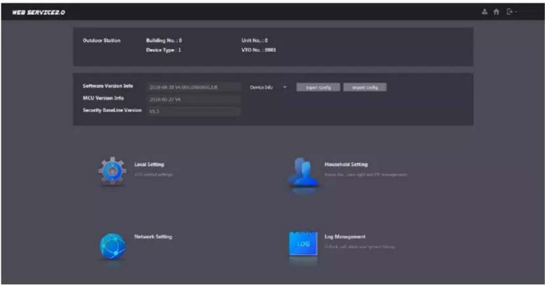
____ Select Local Setting > Basic. Step 2
The device properties are displayed. See Figure 3-4.
Device properties Figure 3-4

Step 3 In the VTO No. input box, enter the VTO number you planned for this VTO, and then click Confirm to save.
3.3.3 Configuring Network Parameters
____ Select Network Setting > Basic. Step 1 The TCP/IP information is displayed. See Figure 3-5.
TCP/IP information Figure 3-5

____ Enter the network parameters you planed, and then click Save. Step 2 The VTO will reboot, and you need to modify the IP address of your PC to the same network segment as the VTO to log in again.
3.3.4 Configuring SIP Server
The SIP server is required in the network to transmit intercom protocol, and then all the VTO and VTH devices connected to the same SIP server can make video call between each other. You can use VTO device or other servers as SIP server.
____ Select Network Setting > SIP Server. Step 1 The SIP Server interface is displayed. See Figure 3-6.
SIP server Figure 3-6
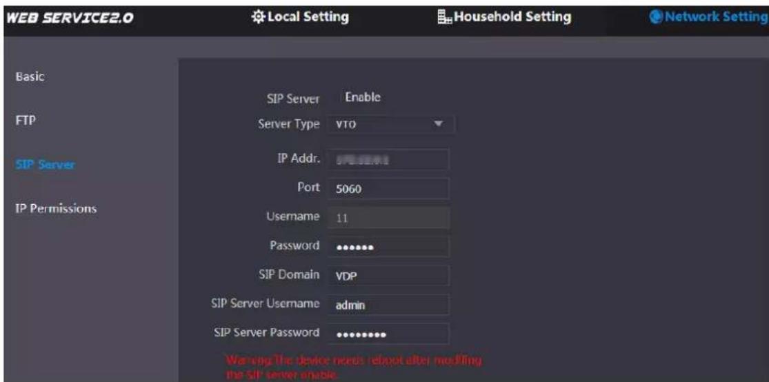
Select the server type you need. Step 2
- If the VTO you are visiting works as SIP server
Select the Enable check box at SIP Server, and then click Save.
The VTO will reboot, and after rebooting, you can then add VTO and VTH devices to this VTO. See the details in "3.3.5 Adding VTO Devices" and "3.3.6 Adding Room Number."

If the VTO you are visiting does not work as SIP server, do not select the Enable check box at SIP Server, otherwise the connection will fail.
- If other VTO works as SIP server
Select VTO in the Server Type list, and then configure the parameters. See Table 3-1.
Table 3-1 SIP server configuration
| Parameter | Description |
| IP Addr. | The IP address of the VTO which works as SIP server. |
| Port | 5060 |
| Username | Keep the default value. |
| Password | |
| SIP Domain | VDP |
| SIP Server Username | The user name and password for the web interface of the SIP server. |
| SIP Server Password |
- If other servers work as SIP server
Select the server type you need in the Server Type list, and then see the corresponding manual for the detailed configuration.
3.3.5 Adding VTO Devices
You can add VTO devices to the SIP server, and all the VTO devices connected to the same SIP server can make video call between each other. This section applies to the condition in which a VTO device works as SIP server, and if you are using other servers as SIP server, see the corresponding manual for the detailed configuration.
Step 1 Log in the web interface of the SIP server, and then select Household Setting > VTO No. Management.
The VTO No. Management interface is displayed. See Figure 3-7.
VTO No. management Figure 3-7

Click Add. Step 2
The Add interface is displayed. See Figure 3-8.
Add VTO Figure 3-8

Table 3-2 Add VTO configuration
| Parameter | Description |
| Rec No. | The VTO number you configured for the target VTO. See the details in "3.3.2 Configuring VTO Number." |
| Register Password | Keep default value. |
| Build No. | Available only when other servers work as SIP server. |
| Unit No. | |
| IP Address | The IP address of the target VTO. |
| Username | The user name and password for the web interface of the target VTO. |
| Password |
Click Save. Step 4
3.3.6 Adding Room Number
You can add the planned room number to the SIP server, and then configure the room number on VTH devices to connect them to the network. This section applies to the condition in which a VTO device works as SIP server, and if you use other servers as SIP server, see the corresponding manual for the detailed configuration.

The room number can contain 6 digits of numbers or letters or their combination at most, and it cannot be the same as any VTO number.
Step 1 Log in the web interface of the SIP server, and then select Household Setting > Room No. Management.
The Room No. Management interface is displayed. See Figure 3-9.
Room No. Management Figure 3-9

____ You can add single room number or do it in batch. Step 2
- Adding single room number
1) Click the Add at the mid lower position. See Figure 3-9.
The Add interface is displayed. See Figure 3-10.
Add single room number Figure 3-10

2) Configure room information. See Table 3-3.
Table 3-3 Room information
| Parameter | Description |
| First Name | Enter the information you need to differentiate each room. |
| Last Name | |
| Nick Name | |
| Room No. | The room number you planned.[TETH]If you use multiple VTH devices, the room number of the master VTH should be "room number#0", and the room number of the extension VTH should be "room number#1", "room number#2", and so on.You can have 10 extension VTH devices at most for one master VTH. |
| Register Type | Selectpublic, andlocalis reserved for future use. |
| Register Password | Keep the default value. |
3) Click Save.
The added room number is displayed. Click to modify room information, and click

to delete a room.
- Adding room number in batch
1) Configure the Unit Layer Amount, Room Amount in One Layer, First Floor Number, and Second Floor Number according to the actual condition.
2) Click the Add at the bottom position. See Figure 3-11
Add in batch Figure 3-11

All the added room numbers are displayed. Click Refresh to view the latest status, and click Clear to delete all the room numbers.
Verifying Configuration 3.4
3.4.1 Calling VTH from VTO
Step 1 Dial room number on the VTO.
____ Press Step 2
The VTO is calling the VTH. See Figure 3-12.
Call screen Figure 3-12

natural_image
Steep garden path with concrete steps and grassy background, displayed within a video editing interface (no readable text or symbols on the main scene)____ Tap on the VTH to answer the call. Step 3
3.4.2 Doing Monitor from VTH
In the main interface of the VTH, select Monitor > Door. Step 1 The Door interface is displayed. See Figure 3-13.
Door Figure 3-13

Select the VTO you need to do monitor. Step 2 The monitor screen is displayed. See Figure 3-14.
Monitor screen Figure 3-14

natural_image
Stepping pathway in a grassy park with green shrubs and a black trash bin, displayed within a video editing interface (no readable text or symbols on the path itself)Call Function 4.1
4.1.1 Calling single VTH
See "3.4.1 Calling VTH from VTO."
4.1.2 Calling Multiple VTH Devices
If the VTO you are visiting works as SIP server, and there are multiple VTH devices being used, when you call the master VTH, all the extension VTH devices would also receive the call.
Before calling, be sure to:
- Enable Group Call in Local Setting > Basic. See the VTO user's manual.
- Add master VTH and the extension VTH. See "3.3.6 Adding Room Number."
4.1.3 Calling Management Center

Unlock Function 4.2
4.2.1 Unlock with Face Recognition

Face recognition is available on select models.
When the VTO is on sleeping mode, and when people are approaching, the screen lights up, and then starts face recognition automatically.
4.2.2 Unlock with Password

4.2.3 Unlock with IC Card
Swipe the authorized access card at the access card area of the VTO to open the door.
4.2.4 Unlock From VTH
You can tap the unlock button on VTH to unlock the door when VTO and VTH are having phone call or you are doing monitor.
4.2.5 Unlock From the Management Center
You can unlock the door from the management center when VTO is calling the management center, VTO and the management center are having phone call, or you are doing monitor from the management center.
Project Mode 4.3
The project mode is only for professional or admin people, and you can make advanced configurations to the VTO under this mode, including issuing access card, modifying device IP address, and adding room number.
4.3.1 Entering Project Mode
On the main interface, enter “☐ +project password+ ☐” to enter project mode.
The default project password is 888888, and you can modify it on the VTO or in the VTO web interface.
In the project mode, you can press ▲ or ▼ to select menu items; press □ as return; press ▢ as confirm.
4.3.2 Modifying IP Address
In the project mode, select IP Settings. Step 1 Press numeric keys of 2, 8, 4, and 6 as directional keys to select the item you need to Step 2 modify, and then press to start input. After inputting, press to confirm. 3 After the modification is finished, press to exit.
4.3.3 Adding Face Data

Face recognition is available on select models.
Step 1 In the project mode, select User Registration.
The Input room number interface is displayed.
Step 2 ____ Enter the room number for the newly added face, and then press

You can add 50 faces at most under one room number.
Step 3 Select Face Registration.
The VTO starts recognizing and adding face data. Press to restart.
____ After the registration is finished, press to confirm, and then press to Step 4 exit.
4.3.4 Issuing Card
In the project mode, select User Registration. Step 1
The Input room number interface is displayed.
____ Enter the number of the room to which you need to issue access card, and then press Step 2

____ You can issue access card with master card or card issuing password. Step 3
- Issue card with master card
Select Issue Card > Master card, and then swipe the master card.

You can issue master card on the SIP server. See the detailed configuration in the corresponding manual.
- Issue card with password
Select Issue Card > Password, then enter the card issuing password, and then press # to confirm.

The default card issuing password is 002236, and you can modify it in the web interface.
See the VTO users' manual.
____ Swipe the card(s) that need to be authorized. Step 4
____ After the registration is finished, press to confirm, and then press again Step 5 to exit.
Packing List
| Open the package and check whether all the components are included. | ||
| Name | Quantity | Info |
| VTO | 1 | |
| Power adapter | 1 | |
| Quick Start Guide | 1 | |
| Screw package | 1 | |

- Model F VTO VTO6441F/VTO6421F
- Cybersecurity Recommendations
- Mandatory actions to be taken towards cybersecurity
- Change Passwords and Use Strong Passwords:
- Update Firmware
- Change Passwords Regularly
- Change Default HTTP and TCP Ports:
- Enable HTTPS/SSL:
- Enable IP Filter:
- Change ONVIF Password:
- Forward Only Ports You Need:
- Disable Auto-Login on SmartPSS:
- Use a Different Username and Password for SmartPSS:
- Limit Features of Guest Accounts:
- UPnP:
- SNMP:
- Multicast:
- Check the Log:
- Physically Lock Down the Device:
- Connect IP Cameras to the PoE Ports on the Back of an NVR:
- Isolate NVR and IP Camera Network
- General
- Safety Instructions
- About the Guide
- Important Safeguards and Warnings
- Operating Requirement
- Power Requirement
- Table of Contents
- Cybersecurity Recommendations....I
- Foreword IV
- Important Safeguards and Warnings ...... V
- Appearance .... 1
- Installation....5
- Configuration.... 11
- Operating VTO 20
- Dimension 1.1
- Front Panel 1.2
- Rear Panel 1.3
- Installation Requirement 2.1
- Notice
- Guidance
- Connecting Cable 2.2
- Door Lock Port
- RS-485 Port
- Alarm I/O and Power Port
- Wiegand Port
- Installing VTO 2.3
- Configuration Process 3.1
- Config Tool 3.2
- Configuring VTO
- Initialization
- Configuring VTO Number
- Main interface Figure 3-3
- Configuring Network Parameters
- Configuring SIP Server
- Adding VTO Devices
- Adding Room Number
- Add single room number Figure 3-10
- Add in batch Figure 3-11
- Verifying Configuration 3.4
- Calling VTH from VTO
- Doing Monitor from VTH
- Call Function 4.1
- Calling single VTH
- Calling Multiple VTH Devices
- Calling Management Center
- Unlock Function 4.2
- Unlock with Face Recognition
- Unlock with Password
- Unlock with IC Card
- Unlock From VTH
- Unlock From the Management Center
- Project Mode 4.3
- Entering Project Mode
- Modifying IP Address
- Adding Face Data
- Issuing Card
- Packing List
Brand : Dahua Technology
Model : VTO6421F
Category : Video Intercom