
WP6 - Remote control BOSS - Free user manual and instructions
Find the device manual for free WP6 BOSS in PDF.


| Product Type | RF Wireless Remote Control for RGB LED Controller |
| Brand | Boss Audio Systems |
| Model | WP6 |
| Design | Ultra Slim |
| Power Supply | 12V DC, Negative Ground |
| Output Current (Peak) | 3 x 4A per channel |
| Output Current (Constant) | 3 x 2A per channel |
| Remote Frequency | 433.92 MHz |
| Remote Range (Open Area) | Greater than 15m |
| Dynamic Modes | 22 modes |
| Static Colors | 20 colors |
| PWM Grade | 256 levels |
| Brightness Grade | 5 levels |
| Speed Grade | 10 levels |
| Demo Mode | Yes (12 dynamic modes in loop) |
| Direct Color Select | Yes |
| Output Color Sequence Options | 6 configurations |
| Maximum Pairing Capacity | Up to 3 remote controllers per main unit |
| Compatibility | Common Anode RGB LED products |
| Maintenance | Do not install in closed metal parts; avoid short circuit or overload |
Frequently Asked Questions - WP6 BOSS
User questions about WP6 BOSS
0 question about this device. Answer the ones you know or ask your own.
Ask a new question about this device
Download the instructions for your Remote control in PDF format for free! Find your manual WP6 - BOSS and take your electronic device back in hand. On this page are published all the documents necessary for the use of your device. WP6 by BOSS.
USER MANUAL WP6 BOSS
- Card Type RF Remote
- Ultra Slim Design
• Dynamic Demo Mode - Easy Remote Pairing
- Direct Color Select
Functions
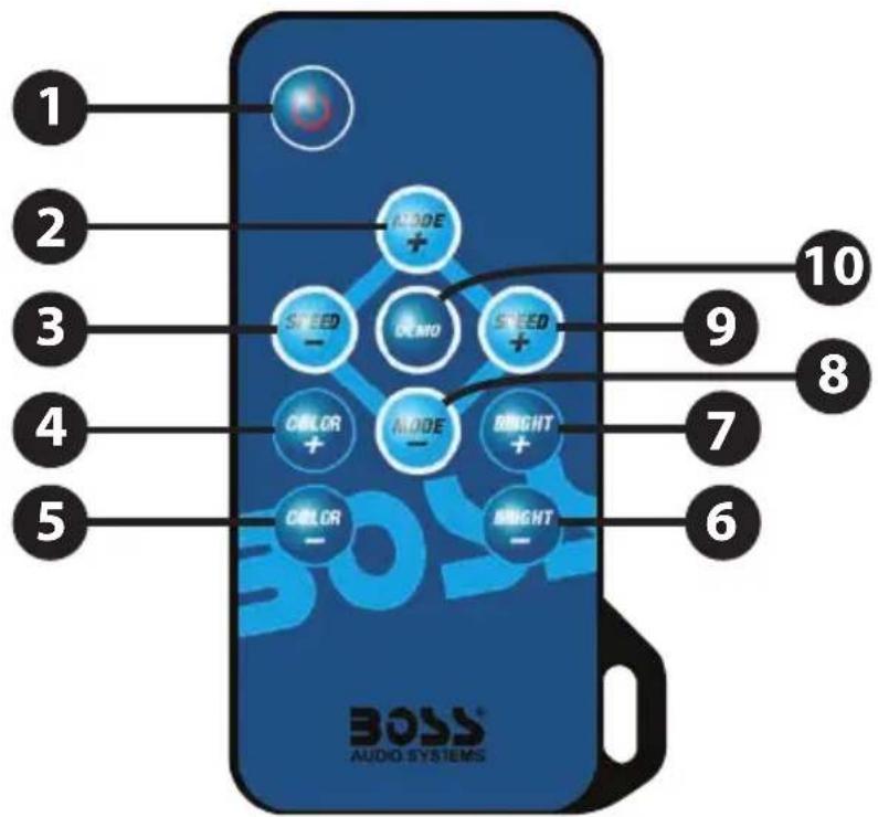
1. Turn On/Standby Mode
Press this key to turn on unit or switch to Standby Mode.
2/8. Dynamic Mode Adjust
Switch to Dynamic Mode from static color, or switch between Dynamic Modes.
3/9. Dynamic Speed Adjust
Adjust Dynamic Playing Speed. Press SPEED+ to increase speed and press SPEED- to decrease. Unit will switch to Dynamic Mode, if this key is pressed during Static Color Mode.
4/5. Static Color Adjust
Switch to Static Color Mode from Dynamic Mode, or press COLOR+ or COLOR-to change colors.
6/7. Brightness Adjust
Adjust static color brightness. Press BRIGHT+ to increase brightness and press BRIGHT- to decrease. Unit will switch to Static Color Mode, if this key is pressed during Dynamic Mode.
10. Demo Mode
Pressing this key will switch to Demo Mode. In Demo Mode, it plays 12 Dynamic Modes in loop, each mode repeats 3 times.
Installing
1. Power Supply
Operational voltage is 12V DC, negative ground. The DC jack's inner pole (or red cable) is positive and sleeve (or black cable) is negative. Also, please make sure the power supply voltage is same as the LED load.
2. LED Output
This unit supports common anode connection LED products. The mark 'A' indicates the common connection node.
The peak output current is 4 amperes and maximum constant current is 2 amperes per channel. Please reduce load if main unit is overheating.
CAUTION! Do not short circuit or overload the LED outputs, this may lead to permanent damage!

Operation
1. Using Remote Controller
Please pull out the battery insulation tape before using. The RF wireless remote signal can pass through barrier, so it's not necessary to aim at the main unit when operating.
For proper receiving remote signal, please do not install the main unit in closed metal parts.
2. Pairing New Remote
The remote and main unit is 1 to 1 paired as default. Furthermore, main unit can be paired to 3 remote controllers and each remote controller can be paired to any main unit. Please do following steps to pair new remote controller:
1). Plug off the power of main unit and plug in after 5 seconds.
2). Press 'SPEED-' and 'SPEED+' Key together in seconds after power on.
After this operation, the main unit will recognize the new remote controller.
3. Free Remote Pairing Mode
In some specific cases, the main unit may need to be paired to any remote control. Please do following steps for free remote pairing mode:
1). Unplug Power cable so the unit is OFF, and plug back in after 5 seconds.
2). Press 'ON/OFF' and 'MODE+' Key together 5 seconds after powering on. After this operation, the main unit will recognize any remote control. To pair the main unit back to specific remote, please repeat the 'pairing New Remote' operation.
4. Switch Output Color Sequence
The controller's default output signal sequence is Common-Green-Red-Blue. If the LED application is in different cable sequence, the direct color keys will not match the LED color.in this case, user can adjust the output signal sequence with following steps:
1). Unplug the power so the main unit is off for 5 seconds.
2). Press 'RED' and 'BLUE' color key together in 5 seconds after powering on. With this operation, the output sequence will switch between 6 possible combinations. The sequence will be stored in memory so on next operation it will be the same.
Specifications
| Dynamic mode | 22 modes |
| Static Color | 20 colors |
| PWM Grade | 256 levels |
| Brightness Grade | 5 levels |
| Speed Grade | 10 levels |
| Demo Mode | Yes |
| Direct Color Select | Yes |
| Output Color Switchable | Yes, 6 options |
| Operational Voltage | 12V DC, negative ground |
| Output Current | 3x4A peak, 3x2A constant |
| Remote Frequency | 433.92MHz |
| Remote Distance | >15m at Open Area |
NOTES
USER'S MANUAL
RF WIRELESS REMOTE
RGB LED CONTROLLER
BOSS®
AUDIO SYSTEMS
BOSS Audio Systems
3451 Lunar Court • Oxnard, CA 93030
www.bossaudio.com
800-999-1236 US Toll-free
805-751-4853 Customer Service
Tech Support: www.bossaudio.com/support/technical-support




- Functions
- Turn On/Standby Mode
- 2/8. Dynamic Mode Adjust
- 3/9. Dynamic Speed Adjust
- 4/5. Static Color Adjust
- 6/7. Brightness Adjust
- Demo Mode
- Installing
- Power Supply
- LED Output
- CAUTION! Do not short circuit or overload the LED outputs, this may lead to permanent damage!
- Operation
- Using Remote Controller
- Pairing New Remote
- Free Remote Pairing Mode
- Switch Output Color Sequence
- NOTES
- USER'S MANUAL
- RF WIRELESS REMOTE
- RGB LED CONTROLLER
- BOSS®
- AUDIO SYSTEMS
Brand : BOSS
Model : WP6
Category : Remote control