
RW3HD - Warming Drawer Wells - Free user manual and instructions
Find the device manual for free RW3HD Wells in PDF.


| Product Type | Warming Drawer |
| Brand | Wells |
| Model | RW3HD |
| Dimensions (W x D x H) | 36 x 22 x 8.5 inches |
| Weight | 45 lbs |
| Power Supply | 120 V, 60 Hz, 15 A |
| Wattage | 1500 W |
| Temperature Range | 150°F – 220°F (65°C – 104°C) |
| Capacity | Up to 20 plates or 3 full-size hotel pans |
| Control Type | Analog thermostat dial |
| Interior Material | Stainless steel |
| Exterior Finish | Stainless steel |
| Installation | Built-in or countertop |
| Ventilation | Front-vented, no rear clearance required |
| Safety Features | Automatic shut-off, cool-touch handle |
| Cleaning | Removable stainless steel racks, wipe with damp cloth |
| Warranty | 1 year limited parts and labor |
Frequently Asked Questions - RW3HD Wells
User questions about RW3HD Wells
0 question about this device. Answer the ones you know or ask your own.
Ask a new question about this device
Download the instructions for your Warming Drawer in PDF format for free! Find your manual RW3HD - Wells and take your electronic device back in hand. On this page are published all the documents necessary for the use of your device. RW3HD by Wells.
USER MANUAL RW3HD Wells
natural_image
Exterior view of a stainless steel kitchen appliance with two doors open, no visible text or symbols on the main body.OWNERS MANUAL
FREE STANDING DRAWER WARMERS with THERMOSTATIC CONTROL
MODELS
RW1HD
RW2HD
RW3HD
RWN1
RWN2
RWN3

natural_image
Exterior view of a two-tiered stainless steel kitchen oven (no visible text or labels)Includes
INSTALLATION
USE & CARE
EXPLODED VIEW
PARTS LIST
WIRING DIAGRAM

natural_image
Silhouette of a person reading a book (no text or symbols visible)IMPORTANT: DO NOT DISCARD THIS MANUAL
This manual is considered to be part of the appliance and is to be given to the OWNER or MANAGER of the restaurant, or to the person responsible for TRAINING OPERATORS of this appliance. Additional manuals are available from your WELLS DEALER.
THIS MANUAL MUST BE READ AND UNDERSTOOD BY ALL PERSONS USING OR INSTALLING THIS APPLIANCE. Contact your WELLS DEALER if you have any questions concerning installation, operation or maintenance of this equipment.
LIMITED WARRANTY STATEMENT
Unless otherwise specified, all commercial cooking equipment manufactured by WELLS MANUFACTURING is warranted against defects in materials and workmanship for a period of one year from the date of original installation or 18 months from the date of shipment from our factory, whichever comes first, and is for the benefit of the original purchaser only.
THIS WARRANTY IS THE COMPLETE AND ONLY WARRANTY, EXPRESSED OR IMPLIED IN LAW OR IN FACT, INCLUDING BUT NOT LIMITED TO, WARRANTIES OF MERCHANTABILITY OR FITNESS FOR ANY PARTICULAR PURPOSE, AND/OR FOR DIRECT, INDIRECT OR CONSEQUENTIAL DAMAGES IN CONNECTION WITH WELLS MANUFACTURING PRODUCTS. This warranty is void if it is determined that, upon inspection by an authorized service agency, the equipment has been modified, misused, misapplied, improperly installed, or damaged in transit or by fire, flood or act of God. It also does not apply if the serial nameplate has been removed, or if service is performed by unauthorized personnel. The prices charged by Wells Manufacturing for its products are based upon the limitations in this warranty. Seller's obligation under this warranty is limited to the repair of defects without charge by a Wells Manufacturing factory authorized service agency or one of its sub-service agencies. This service will be provided on customer's premises for non-portable models. Portable models (a device with a cord and plug) must be taken or shipped to the closest authorized service agency, transportation charges prepaid, for service. In addition to restrictions contained in this warranty, specific limitations are shown in the Service Policy and Procedure Guide. Wells Manufacturing authorized service agencies are located in principal cities. This warranty is valid in the United States and Canada and void elsewhere. Please consult your classified telephone directory, your food-service equipment dealer or contact:
Wells Manufacturing
10 Sunnen Dr., St. Louis MO 63143 USA
phone (314) 678-6314 or fax (314) 781-2714
for information and other details concerning warranty.
SERVICE POLICY AND PROCEDURE GUIDE and ADDITIONAL WARRANTY EXCLUSIONS
- Resetting of safety thermostats, circuit breakers, over load protectors, and/or fuse replacements are not covered by this warranty unless warranted conditions are the cause.
- All problems due to operation at voltages or phase other than specified on equipment nameplates are not covered by this warranty. Conversion to correct voltage and/or phase must be the customer's responsibility.
- All problems due to electrical connections not made in accordance with electrical code requirements and wiring diagrams supplied with the equipment are not covered by this warranty.
- Replacement of items subject to normal wear, to include such items as knobs, light bulbs; and, normal maintenance functions including adjustments of thermostats, adjustment of micro switches and replacement of fuses and indicating lights are not covered by warranty.
- Damage to electrical cords and/or plug due to exposure to excessive heat are not covered by this warranty.
- Full use, care, and maintenance instructions supplied with each machine. Noted maintenance and
preventative maintenance items, such as servicing and cleaning schedules, are customer responsibility. Those miscellaneous adjustments noted are customer responsibility. Proper attention to preventative maintenance and scheduled maintenance procedures will prolong the life of the appliance.
- Travel mileage is limited to sixty (60) miles from an Authorized Service Agency or one of its sub-service agencies.
- All labor shall be performed during regular working hours. Overtime premium will be charged to the buyer.
- All genuine Wells replacement parts are warranted for ninety (90) days from date of purchase on non-warranty equipment. This parts warranty is limited only to replacement of the defective part(s). Any use of non-genuine Wells parts completely voids any warranty.
- Installation, labor, and job check-outs are not considered warranty and are thus not covered by this warranty.
- Charges incurred by delays, waiting time or operating restrictions that hinder the service technician's ability to perform service are not covered by warranty. This includes institutional and correctional facilities.
SHIPPING DAMAGE CLAIM PROCEDURE
NOTE: For your protection, please note that equipment in this shipment was carefully inspected and packaged by skilled personnel before leaving the factory. Upon acceptance of this shipment, the transportation company assumes full responsibility for its safe delivery.
IF SHIPMENT ARRIVES DAMAGED:
-
VISIBLE LOSS OR DAMAGE: Be certain that any visible loss or damage is noted on the freight bill or express receipt, and that the note of loss or damage is signed by the delivery person.
-
FILE CLAIM FOR DAMAGE IMMEDIATELY: Regardless of the extent of the damage.
-
CONCEALED LOSS OR DAMAGE: if damage is unnoticed until the merchandise is unpacked, notify the transportation company or carrier immediately, and file "CONCEALED DAMAGE" claim with them. This should be done within fifteen (15) days from the date the delivery was made to you. Be sure to retain the container for inspection.
Wells Manufacturing cannot assume liability for damage or loss incurred in transit. We will, however, at your request, supply you with the necessary documents to support your claim.
TABLE OF CONTENTS
| WARRANTY | xi |
| SPECIFICATIONS | 1 |
| FEATURES & OPERATING CONTROLS 2 | |
| PRECAUTIONS & GENERAL INFORMATION 3 | |
| AGENCY LISTING INFORMATION 3 | |
| INSTALLATION | 4 |
| OPERATION | 6 |
| CLEANING INSTRUCTIONS 8 | |
| TROUBLESHOOTING SUGGESTIONS 9 | |
| MAINTENANCE INSTRUCTIONS 10 | |
| EXPLODED VIEW & PARTS LIST 11 | |
| WIRING DIAGRAM 13 | |
| PARTS & SERVICE 17 | |
| CUSTOMER SERVICE DATA 17 |
INTRODUCTION
Thank You for purchasing this Wells Manufacturing appliance.
Proper installation, professional operation and consistent maintenance of this appliance will ensure that it gives you the very best performance and a long, economical service life.
This manual contains the information needed to properly install this appliance, and to use and care for the appliance in a manner which will ensure its optimum performance.
SPECIFICATIONS
| MODELS | VOLTS50/60 Hz 1ø | WATTS AMPS | POWERCORD | |
| RW1HD, RWN1 | 120 VAC 450 | W 3.8 NEMA-5-15P | ||
| 208/240 VAC | 338/450 W | 1.6/1.9 | NEMA 6-15P | |
| RW2HD, RWN2 | 120 VAC 900 | W 7.5 NEMA-5-15P | ||
| 208/240 VAC | 676/900 W | 3.3/3.8 | NEMA 6-15P | |
| RW3HD, RWN3 | 120 VAC | 1350 W | 11.3 | NEMA-5-15P |
| 208/240 VAC | 1014/1350 W | 4.9/5.6 | NEMA 6-15P | |
FEATURES & OPERATING CONTROLS
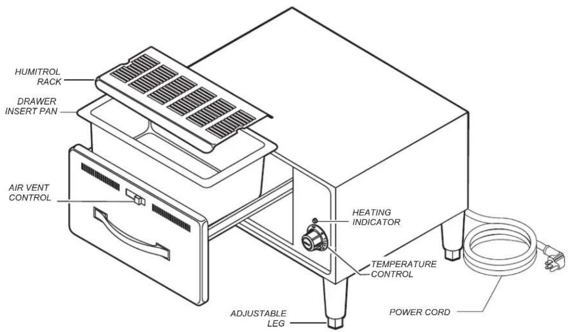
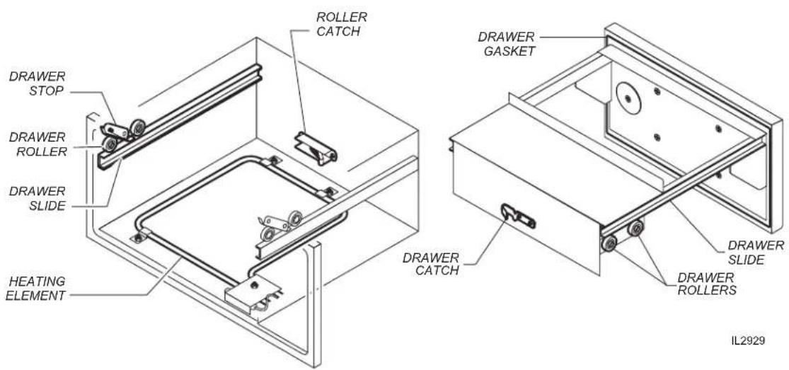
M041 p/n 2M-303335 Owners Manual Free-Standing Drawer Warmer
PRECAUTIONS AND GENERAL INFORMATION
This appliance is intended for use in commercial establishments only.
This appliance is intended to prepare food for human consumption. No other use is recommended or authorized by the manufacturer or its agents.
Operators of this appliance must be familiar with the appliance use, limitations and associated restrictions. Operating instructions must be read and understood by all persons using or installing this appliance.
Cleanliness of this appliance is essential to good sanitation. Read and follow all included cleaning instructions and schedules to ensure the safety of the food product.
Disconnect this appliance from electrical power before performing any maintenance or servicing.
DO NOT submerge this appliance in water. This appliance is not jet stream approved. Do not direct water jet or steam jet at this appliance, or at any control panel or wiring. Do not splash or pour water on, in or over any controls, control panel or wiring. Do not wash floor around this appliance with water or steam jet.
Exposed surfaces of this appliance can be hot to the touch and may cause burns.
Heating element will be very hot when in use. Contact may cause serious burns.
The technical content of this manual, including any wiring diagrams, schematics, parts breakdown illustrations and/or adjustment procedures, is intended for use by qualified technical personnel.
Any procedure which requires the use of tools must be performed by a qualified technician.
This manual is considered to be a permanent part of the appliance. This manual and all supplied instructions, diagrams, schematics, parts breakdown illustrations, notices and labels must remain with the appliance if it is sold or moved to another location.
This appliance is made in the USA. Unless otherwise noted, this appliance has American sizes on all hardware.

WARNING: ELECTRIC SHOCK HAZARD
All servicing requiring access to non-insulated electrical components must be performed by a factory authorized technician. DO NOT open any access panel which requires the use of tools. Failure to follow this warning can result in severe electrical shock.

CAUTION: RISK OF DAMAGE
DO NOT connect or energize this appliance until all installation instructions are read and followed. Damage to the appliance will result if these instructions are not followed.

CAUTION: HOT SURFACE
Exposed surfaces can be hot to the touch and may cause burns.
AGENCY LISTING INFORMATION
This appliance conforms to NSF Standard 4 for sanitation only if installed in accordance with the supplied Installation Instructions and maintained according to the instructions in this manual.
IMPORTANT:
RW- models are NOT NSF approved for potentially hazardous foods.
This appliance is 📁 and 🌐 Listed under UL File E6070 for 120V, 208V and 240V.

STD 4

E6070

E6070
INSTALLATION
NOTE: DO NOT discard the carton or other packing materials until you have inspected the appliance for hidden damage and tested it for proper operation. Refer to SHIPPING DAMAGE CLAIM PROCEDURE on the inside front cover of this manual.

WARNING: RISK OF INJURY
Installation procedures must be performed by a qualified technician with full knowledge of all applicable electrical and plumbing codes. Failure can result in personal injury and property damage.
UNPACKING & INSPECTION
Carefully remove the appliance from the carton. Remove all protective plastic film, packing materials and accessories from the Appliance before connecting electrical power or otherwise performing any installation procedure.
Carefully read all instructions in this manual and the Installation Instruction Sheet packed with the appliance before starting any installation.
Read and understand all labels and diagrams attached to the appliance.
Carefully account for all components and accessories before discarding packing materials. Store all accessories in a convenient place for later use.
COMPONENTS
1 - 3 ea. DRAWERS (qty. depends on model)
1 - 3 ea. HUMITROL RACKS (if ordered with unit)
SETUP
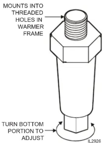
Install adjustable legs or optional casters, one on each corner of the appliance, in the holes provided.
Verify that the unit sits firmly on ALL FOUR legs. With a spirit level, check that the appliance is level front-to-back and side-to-side. With the adjustable legs, adjust as required to level the appliance. All four legs must be adjusted to firmly contact the floor in order to prevent tipping.
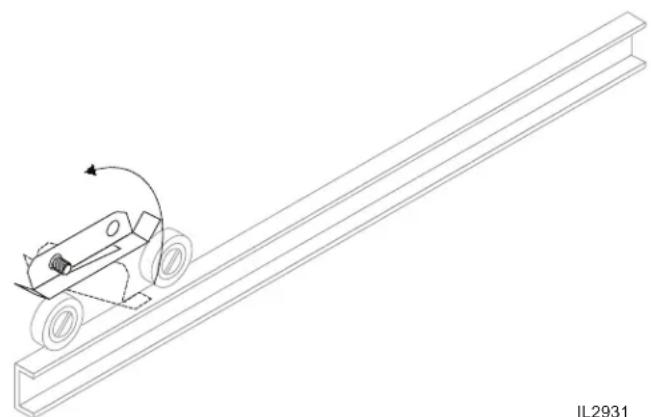
If drawers were removed during installation, install drawer(s) in unit:
a. Check the roller catch inside the cabinet. The spring-loaded roller arm must be extended.
b. With the front of the drawer assembly tipped downward, engage the roller on the drawer with the cabinet drawer slide.
c. Raise the drawer to the horizontal position until the drawer-mounted slide engages the dual roller assembly on the cabinet.
d. Slide the drawer in until the catch engages. The drawer should remain tightly closed.
e. Slide the drawer out. The drawer stop should prevent the drawer from coming all of the way out.
f. Install drawer insert pans.
Avoid storing flammable or combustible materials in, on or near the appliance.
INSTALLATION (continued)
ELECTRICAL
Refer to electrical specifications on page 1. Circuit must meet or exceed the amperage and wattage requirements listed.
120 Volt units require a properly grounded NEMA 5-15R receptacle:

208/240 Volt units require a properly grounded NEMA 6-15R receptacle:

WARNING: SHOCK HAZARD
All servicing requiring access to non-insulated electrical components must be performed by a factory authorized technician. DO NOT open any access panel which requires the use of tools. Failure to follow this warning can result in severe electrical shock.
CAUTION: RISK OF DAMAGE
DO NOT connect or energize this appliance until all installation instructions are read and followed. Damage to the appliance will result if these instructions are not followed.

CAUTION: SHOCK HAZARD
The ground prong of the power cord is part of a system designed to protect you from electric shock in the event of internal damage. DO NOT cut off the large round ground prong, or twist a blade to fit an existing receptacle.
IMPORTANT:
Contact a licensed electrician to install and connect electrical power to the appliance.
IMPORTANT:
Damage due to being connected to the wrong voltage or phase is NOT covered by warranty.
OPERATION

CAUTION: HOT SURFACE
Exposed surfaces can be hot to the touch and may cause burns.

NOTE:
The chart below is intended as a guide ONLY. Your own experience with this appliance, type of foods and method of operation will enable you to determine the temperature control and air vent settings best suited to your operation.
HEATING OPTIONS
- Moist heat with Humitrol Rack:
a. MOIST operation prevents food from drying out as heat is applied to the warming chamber.
b. To set for MOIST operation, remove the Humitrol Rack from bottom of drawer insert pan and carefully pour approximately 2 quarts of water ( 12 ” depth) into the pan. Reinstall rack.
c. When the drawer is closed, the Humitrol Rack allows water vapor to rise through the stored product in the drawer. The Humitrol Rack also decreases the sloshing effect of the water in the pan when the drawer is opened.
d. Place the food directly on the rack. The rack is designed to support the food off of the steam vents, where water droplets may form.
e. Check the water level in the pan periodically, and add water when necessary.
f. Set the front air vent between fully closed and half-open.
Actual setting will depend upon the type and amount of product stored in the drawer, the temperature setting, and the frequency with which the drawer is opened.
- Moist heat with pans:
a. This Wells warmer is designed to accommodate any combination of standard-size, steam table pans.
b. Place a small amount of water in drawer pan. Place the steam table pans in the drawer pan.
c. Check the water level in the pan periodically, and add water when necessary.
- Dry heat:
a. For some applications, you may want to store previously prepared foods in a dry-heat environment. To do so, place the food directly into the empty (i.e. no water) drawer pan.
OPERATING CHART FOR DRAWER WARMERS
| PRODUCT TYPE | RECOMMENDED STORAGE TEMP. | TYPE OF HEAT | CONTROL SETTINGS | AIR VENT SETTINGS | |
| Hard Rolls 160-185°F | 71-85°C | Dry 7-8 Full Open | |||
| Soft Rolls | 150-175°F | 65-79°C | Moist | 6-7 | Open - 1⁄2 |
| Vegetables | 175-185°F | 79-85°C | Moist | 7-8 | Open - 1⁄2 |
| Meats | 165-185°F | 74-85°C | Dry | 6-8 | Full Open |
| Fish | 165-185°F | 74-85°C | Moist | 6-8 | Closed |
| Casseroles | 150-175°F | 65-79°C | Dry | 6-7 | Full Open |
| Pies, Desserts | 160-185°F | 65-85°C | Dry | 6-7 | Full Open |
| Taco Shells | 150-170°F | 65-76°C | do not put water in the pan | 4-6 Full Open | |
| Corn Chips | 150-170°F | 65-76°C | 4-6 | Full Open | |
OPERATION (continued)
OPERATION
- Determine the type of food to be warmed.
- Refer to the chart on page 6 to determine the type of heat required.
- Set the air vent control for the type of heat, and rotate the thermostat knob to the temperature setting desired.
- Allow warmer to pre-heat for approximately 30 minutes before use.
DO'S and DON'TS
- DO Always use a drawer pan.
DO NOT Place food directly into the warmer cavity. -
DO Check water level in moist-operation warmer frequently during use. DO Use a Humitrol Rack or Insets to hold food for moist operation.
-
DO Use warm water to add to the pan during moist operation.
DO NOT Put ice into a warmer pan. Ice in the pan will cause condensation on the inside of the warmer cavity.

CAUTION: HOT SURFACE
Exposed surfaces can be hot to the touch and may cause burns.
CAUTION:
SHOCK HAZARD
DO NOT splash or pour water onto control panel or wiring.
IMPORTANT:
DO NOT place food directly into the warmer cavity. Always use a drawer pan.
IMPORTANT:
DO NOT put ice into a warmer pan. Ice in the pan will cause condensation on the inside of the warmer cavity. Damage caused by this type of condensation is NOT covered by warranty.
CLEANING INSTRUCTIONS
CAUTION: SHOCK HAZARD
Disconnect appliance from electric power before cleaning.

CAUTION: HOT SURFACE
Exposed surfaces can be hot to the touch and may cause burns. Allow appliance to cool before cleaning.
PRECAUTIONS: Turn control knob to OFF. Allow drawers to cool before proceeding. Remove drawer pans and Humitrol racks.
FREQUENCY: Minimum - Daily
TOOLS: Warm water and mild detergent Clean cloth or sponge
- Remove drawers from warmer:
a. Pull warmer drawer out until fully extended.
b. Slide finger along left and right slide rail until you reach the latches (located at the front end of the cabinet-mounted rails) Press down on both left and right latch.
c. Pull drawer away from warmer.
natural_image
Technical line drawing of a mechanical roller system with a moving cart and rotation arrow (no text or symbols)- Clean drawers, drawer pans, Humitrol Racks and/or insets with warm water and mild detergent.
Rinse all components thoroughly with clear water. Dry all components prior to reinstalling them in warmer.
- Sweep crumbs and other debris from warmer cavity.
- Clean the outside of the unit by wiping with a clean cloth or sponge, warm water and mild detergent. Dry with a clean cloth, then wipe with a polish formulated for stainless steel.
- It is important to keep the slide rails clear and free from debris. Periodic cleaning of the slide rails and other adjoining parts is necessary to assure smooth drawer operation.
- Check drawer rollers. Be sure they roll freely and that the slide rails are free from debris.
- Be sure cabinet-mounted drawer catch roller is "up", then re-install drawers.
TROUBLESHOOTING SUGGESTIONS
| SYMPTOM POSSIBLE CAUSE SUGGESTED REMEDY | ||
| No lights or heat (all drawers) | Warmer unplugged Plug warmer into appropriate receptacle | |
| Circuit breaker off or tripped Reset circuit breaker | ||
| Internal damage | Contact an Authorized Wells Service Agency for repairs. | |
| No heat (one drawer) | Temperature control not set Set for desired temperature. | |
| Internal damage | Contact an Authorized Wells Service Agency for repairs. | |
| Food dries out | Humidity control (air vent) not set | OPEN air vent for dry operation.CLOSE air vent for moist operation. |
| Water in pan evaporated or low Add water to pan. | ||
| Food gets soggy | Food contacting water Use a Humitrol Rack | |
| Water level too high | Water should be no more than 1/2" deep | |
| Humidity control (air vent) not set | OPEN air vent for dry operation.CLOSE air vent for moist operation. | |
| Drawer falls open | Catch roller not extended before closing drawer | Be sure catch roller is extended before installing drawer. |
| Drawer catch damaged | Contact an Authorized Wells Service Agency for repairs. | |
| Drawer falls out when opened | Drawer stop dirty Clean and lubricate drawer stop | |
| Drawer stop damaged | Contact an Authorized Wells Service Agency for repairs. | |
MAINTENANCE INSTRUCTIONS (continued)

CAUTION: SHOCK HAZARD
Disconnect appliance from electric power before cleaning.

CAUTION: HOT SURFACE
Exposed surfaces can be hot to the touch and may cause burns. Allow appliance to cool before servicing.
ADJUSTMENTS AND LUBRICATION
PRECAUTIONS: Turn control knob to OFF. Unplug warmer Allow drawers to cool before proceeding. Remove drawer pans and Humitrol racks
FREQUENCY: Minimum - monthly. Every 2 weeks recommended.
TOOLS: Screwdrivers, Phillips (+) and flat blade (-). Nut drivers, 3/8" and 7/16". Food-grade lubricant.
- Check slides on cabinet and drawers for cleanliness.
- Check all rollers on cabinet and drawers for cleanliness and tightness. Lubricate.
- Check cabinet drawer stops for operation. Stops must "snap" down positively. Clean and adjust as required.
- Check cabinet heating element fasteners for tightness.
- Check all cabinet drawer catches for tightness and operation. Lubricate. Be certain roller is "out" before attempting to install drawer.
- Check thermostat thermo-bulb and capillary tube for condition. Thermo-bulb must be securely mounted in the appropriate holder. Arrange repairs for damaged thermo-bulb or capillary tube.
- Check drawer faceplate and handle fasteners for tightness.
- Check drawer catch clip for tightness.
- For drawers equipped with gaskets, examine condition of gasket. Arrange repairs for torn or damaged gaskets.
- Reinstall drawers and check for proper operation.
Procedure is complete.

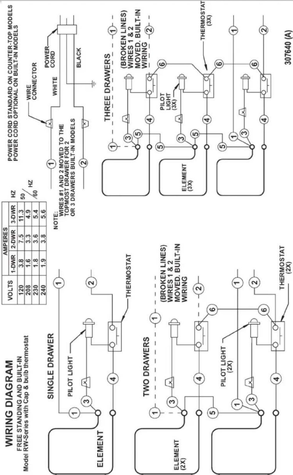
WIRING DIAGRAM
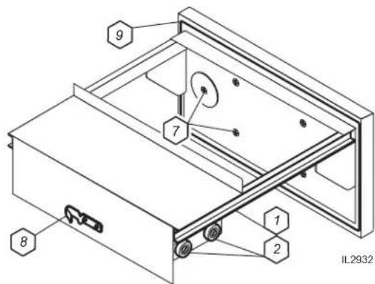
EXPLODED VIEW & PARTS LIST: RW1HD, RW2HD, RW3HD
DRAWER ASSEMBLY - COMMON TO ALL HD VERSIONS

CAVITY and CABINET INERIOR - COMMON TO ALL HD VERSIONS

EXPLODED VIEW & PARTS LIST
RW1HD, RW2HD, RW3HD, DRAWER WARMER
| Fig No Part No. Description | |
| 1 WS-20624 RACK HUMITROL RWS (OPTIONAL) | |
| 2 C8-46840 PAN INSERT DRAWER RWHD | |
| 3 WS-67096 DRAWER ASSY KIT RWHD | |
| 4 C8-32112 HANDLE RW DRAWER SRW320 | |
| 5 WS-51796 KNOB SQUARE ROLL WARMER VENT | |
| 6 C8-49251 SLIDE VENT ASSY RWN | |
| 7 2C-35530 SCREW, 8-32 X 3/8 PH, RD-EACH | |
| 8 2C-35565 WASHER 2 1/16 DRWR BACK | |
| 9 2C-35487 SCREW 8-32X5/16 PH TR HD | |
| 10 2C-35455 NUT 8-32 HEX MS SS | |
| 11 2C-30471 DRAWER STRIKE AND CATCH | |
| 12 2P-30483 BRNG RLLR TRK-R116 | |
| 13 C8-45335 DRAWER WELD ASSY RWHD | |
| 14 2C-49395 RIVIT POP 1/8 X .265 SS | |
| 15 | 2N-30482UL ELEM 240V 450V |
| 2N-30519UL ELEM 120V 450W, ROLL WRMR | |
| 16 2T-44475 THERMOMETER RW 2IN DIAL | |
| 17 2J-35687 LT SGNL | |
| 18 WS-58936 THERMO CTL KIT RW W/O AUX | |
| 19 2C-43271 CLIP RETAINER PILOT LIGHT | |
| 20 2R-30372 KNOB CONTROL ASSY, WARMER | |
| 21 C8-Z12392 CONTROL PANEL | |
| 22 | WS-65923 REPR KIT-DWR STOP W/ 6 COIL SPRING |
| C8-507819 REPR KIT-DWR STOP W/ 3 COIL SPRING | |
| 23 C8-35683 SHIELD BULB RWS | |
| 24 C8-35677 ANGLE SUPPORT ELEM RWS | |
| 25 2C-35455 NUT 8-32 HEX MS SS | |
| NI | 2E-35540 CORD SET |
EXPLODED VIEW & PARTS LIST: RWN1, RWN2, RWN3
DRAWER ASSEMBLY - COMMON TO ALL "NARROW" VERSION RWN-SERIES DRAWERS

CAVITY and CABINET INTERIOR - COMMON TO ALL "NARROW" VERSION

M041 p/n 2M-303335 Owners Manual Free-Standing Drawer Warmer
EXPLODED VIEW & PARTS LIST
RWN1, RWN2, RWN3, DRAWER WARMER
| Fig No Part No. Description | |
| 1 WS-20624 RACK HUMITROL RWS (OPTIONAL) | |
| 2 C8-49252 INSERT DRAWER RWN | |
| 3 WS-69244 DRAWER ASSY RWN | |
| 4 WS-69248 HANDLE DRWR RWN | |
| 5 WS-51796 KNOB SQUARE ROLL WARMER VENT | |
| 6 C8-49251 SLIDE VENT ASSY RWN | |
| 7 2C-35530 SCREW, 8-32 X 3/8 PH, RD-EACH | |
| 8 2C-35565 WASHER 2 1/16 DRWR BACK | |
| 9 2C-35487 SCREW 8-32X5/16 PH TR HD | |
| 10 | 2C-35455 NUT 8-32 HEX MS SS |
| 11 | 2C-30471 DRAWER STRIKE AND CATCH |
| 12 | 2P-30483 BRNG RLLR TRK-R116 |
| 13 | WS-69244 DRAWER ASSY RWN |
| 14 | 2C-49395 RIVIT POP 1/8 X .265 SS |
| 15 | 2N-49255UL ELEM 120V 450W RWN |
| 2N-49475UL ELEM 240V 450W RWN | |
| 16 | 2T-44475 THERMOMETER RW 2IN DIAL |
| 17 | 2J-35687 LT SGNL |
| 18 | WS-58936 THERMO CTL KIT RW W/O AUX |
| 19 | 2C-43271 CLIP RETAINER PILOT LIGHT |
| 20 | 2R-30372 KNOB CONTROL ASSY, WARMER |
| 21 | C8-Z12394 CONTROL PANEL |
| 22 | C8-35988 STOP DRWR RWS |
| 23 | 2A-45405 SPACER DRWR STOP SS RWW |
| 24 | C8-35677 ANGLE SUPPORT ELEM RWS |
| 25 | C8-35683 SHIELD BULB RWS |
| NI 2E-35540 CORD SET | |
NOTES
PARTS & SERVICE
DESCRIPTION PART NO.
PAN, STAINLESS (ALL EXCEPT RWN) C8-46840
PAN, STAINLESS (RWN ONLY) C8-49252
LEG KIT, 4" PLASTIC (SET OF 4) WS-20314
LEG KIT, 4" METAL (SET OF 4) WS-20563
LEG KIT, 6" METAL (SET OF 4) WS-21607
CASTER KIT 10" HIGH (SET OF 4) WS-21034
CASTER KIT 3-1/2" HIGH (SET OF 4) WS-21947
CASTER KIT 2-1/4" HIGH (SET OF 4) WS-22025
IMPORTANT: Use only factory authorized service parts and replacement filters.
For factory authorized service, or to order factory authorized replacement parts, contact your Wells authorized service agency, or call:
Wells Manufacturing
10 Sunnen Dr.,
St. Louis MO 63143 USA
Service Dept.
phone: (314) 678-6314
fax: (314) 781-2714
Service Parts Department can supply you with the name and telephone number of the WELLS AUTHORIZED SERVICE AGENCY nearest you.
CUSTOMER SERVICE DATA
Please have this information available if calling for service
RESTAURANT LOCATION
INSTALLATION DATE ____ TECHNICIAN ____
SERVICE COMPANY
ADDRESS ____ STATE ____ ZIP ____
TELEPHONE NUMBER (____) - ____
EQUIPMENT MODEL NO. ____
EQUIPMENT SERIAL NO. ____
VOLTAGE: (check one) ☐ 120 ☐ 208 ☐ 240

Wells Bloomfield proudly supports CFESA Commercial Food Equipment Service Association
SERVICE TRAINING - QUALITY SERVICE
CUSTOMER SATISFACTION

WELLS MANUFACTURING
10 Sunnen Dr., St. Louis, MO 63143
telephone: 314-678-6314
fax: 314-781-2714
www.wellsbloomfield.com

- OWNERS MANUAL
- FREE STANDING DRAWER WARMERS with THERMOSTATIC CONTROL
- IMPORTANT: DO NOT DISCARD THIS MANUAL
- LIMITED WARRANTY STATEMENT
- SERVICE POLICY AND PROCEDURE GUIDE and ADDITIONAL WARRANTY EXCLUSIONS
- SHIPPING DAMAGE CLAIM PROCEDURE
- IF SHIPMENT ARRIVES DAMAGED:
- INTRODUCTION
- FEATURES & OPERATING CONTROLS
- PRECAUTIONS AND GENERAL INFORMATION
- WARNING: ELECTRIC SHOCK HAZARD
- CAUTION: RISK OF DAMAGE
- CAUTION: HOT SURFACE
- AGENCY LISTING INFORMATION
- IMPORTANT:
- INSTALLATION
- WARNING: RISK OF INJURY
- UNPACKING & INSPECTION
- COMPONENTS
- SETUP
- INSTALLATION (continued)
- ELECTRICAL
- WARNING: SHOCK HAZARD
- CAUTION: SHOCK HAZARD
- OPERATION
- NOTE:
- HEATING OPTIONS
- OPERATION (continued)
- DO'S and DON'TS
- CLEANING INSTRUCTIONS
- TROUBLESHOOTING SUGGESTIONS
- MAINTENANCE INSTRUCTIONS (continued)
- ADJUSTMENTS AND LUBRICATION
- WIRING DIAGRAM
- EXPLODED VIEW & PARTS LIST: RW1HD, RW2HD, RW3HD
- EXPLODED VIEW & PARTS LIST
- EXPLODED VIEW & PARTS LIST: RWN1, RWN2, RWN3
- NOTES
- PARTS & SERVICE
- DESCRIPTION PART NO.
- CUSTOMER SERVICE DATA
- WELLS MANUFACTURING
Brand : Wells
Model : RW3HD
Category : Warming Drawer