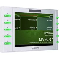
TSW-732-W-S - Television Crestron - Free user manual and instructions
Find the device manual for free TSW-732-W-S Crestron in PDF.


| Product Type | Touch Screen Control Panel |
| Brand | Crestron |
| Model | TSW-732-W-S |
| Display Size | 7 inches (diagonal) |
| Display Type | Color TFT Active Matrix |
| Touch Technology | Projected Capacitive |
| Resolution | 1024 x 600 pixels |
| Dimensions (W x H x D) | 8.6 in x 5.6 in x 2.2 in (218 mm x 142 mm x 56 mm) |
| Weight | 1.9 lb (0.86 kg) |
| Power Source | PoE (Power over Ethernet) or external 24VDC power supply |
| Power Consumption | 15 W (typical) |
| Mounting Type | Wall mount (standard single-gang backbox) |
| Ethernet Port | 10/100 Mbps |
| Operating System | Crestron 3-Series or later (control system) |
| Main Functions | Control lighting, shades, HVAC, audio, video, and security systems |
| Audio | Built-in mono speaker and microphone |
| Video | Not applicable (no video input) |
| Communication Protocols | Crestron Fusion, Crestron XiO Cloud, SNMP, BACnet |
| Cleaning Instructions | Wipe with a soft, dry cloth. Do not use liquids or abrasives. |
| Safety | Install in accordance with local electrical codes. Disconnect power before servicing. |
| Spare Parts & Repairability | Contact Crestron for service. No user-serviceable parts. |
| Additional Information | Supports Crestron Smart Graphics and web browsing. |
Frequently Asked Questions - TSW-732-W-S Crestron
User questions about TSW-732-W-S Crestron
0 question about this device. Answer the ones you know or ask your own.
Ask a new question about this device
Download the instructions for your Television in PDF format for free! Find your manual TSW-732-W-S - Crestron and take your electronic device back in hand. On this page are published all the documents necessary for the use of your device. TSW-732-W-S by Crestron.
USER MANUAL TSW-732-W-S Crestron
7" Room Scheduling Touch Screen
DO Change the Button Inserts or Button Covers
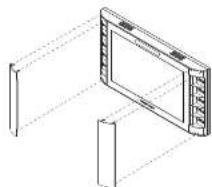
The Crestiron® TSW-732 Touch Screen shoe with 10 "hard key" push buttons for quick access to commonly used functions. Optional, custom engravable button covers are available (TSW-730-BTNO and custom engraving sold separately). For a clean appearance, either column of buttons may be removed and covered using the included no-button covers.
To change the inserts or covers, use the following procedure:
- Insert a small flat head screwdriver into the appropriate hole on the bottom of the TSW-732 to release its cover.

-
Gently remove the cover from the TSW-782.
-
If removing the button insert after removing the button cover, use a small flat head screwdriver to press the tube, and then gently lift the button insert from the TSW-732. Refer to the following illustration for the tab locations on the button insert.
1023 Screen with Button inserts

- Carefully position the new cover over the front of the touch screen and press it into place.
Touch Screen with No-Bucket Covers
natural_image
Isometric line drawing of a device with screen and vertical supports (no text or symbols)DO Install the Touch Screen
The TSW-732 can be mounted into a standard electrical box or onto a flat surface. A tabletop enclosure and swivel mount (TSW-730-TTK and SMK-1SM/730, both sold separately) are also available.
Mounting Into a U.S. Electrical Box
To mount the TSW-732 into a U.S. electrical box, use the following procedure:
- Insert a small flat head screwdriver into the hole shown in the following illustration, and gently separate the back panel from the touch screen.

- Use the four included 9-32 x 1-1/2" screws to attach the back panel to the electrical box.

- Make connections to the TSW-732 using Crestron power supplies for Crestron equipment.

DO Check the Box
| QUANTITY | PRODUCT | COLOR | PART NUMBER |
| 1 | Bit, Torx, T6 20259'5 | ||
| 1 | Cover, Plastic, No Buttons, Left Side, 4.5" × 1" × 0.825" | Black 2033452 | |
| 1 | Cover, Plastic, No Buttons, Left Side, 4.5" × 1" × 0.825" | White 2033451 | |
| 1 | Cover, Plastic, No Buttons, Right Side, 4.5" × 1" × 0.825" | Black 2033450 | |
| 1 | Cover, Plastic, No Buttons, Right Side, 4.5" × 1" × 0.825" | White 2033449 | |
| 2 | Screw, 4D x 3/4", Flat Head, Phillips 2019088 | ||
| 2 | Screw, 4-4D x 1/4", Undercut Head, Phillips | Black 2007102 | |
| 2 | Screw, 4-4D x 1/4", Undercut Head, Phillips | 2007100 | |
| 2 | Screw, 4-4D x 1/4", Flat Head, Torx | Black 2025311 | |
| 2 | Screw, 4-4D x 1/4", Flat Head, Torx | 2025312 | |
| 4 | Screw, 6-32 x 1-1/2", Flat Head, Phillips 2031703 |
- The question of the 1987-2013
PIN DESCRIPTION

A. Carefully position the front of the touch screen over the back panel and gently snap it into place.
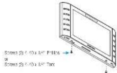
5. Use two of the included 4-40 x 1/4" screws to secure the TSW-732. For standard applications, use the Philips screws. For secure applications, use the security type Torx screws along with the Included Torx screwdriver bit.

Mounting Into a U.K. Electrical Box
To mount the TSW-732 into a U.K. electrical box, use the following procedure:
- Insert a small flat head screwdriver into the hole shown in the following illustration, and gently separate the back panel from the touch screen.
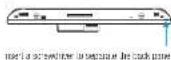

- Use the two included 48 x 3/4" screws to attach the back panel to the electrical box.

- Make connections to the TSW-732 using Crestron power supplies for Crestron equipment.

natural_image
Pure electrical circuit lines without any symbolsOccupancy Sensor Input From Room Occupancy Screen LAN 0.2 10845-1 / 10845+ - X Chromet to LAN
| PIN DESCRIPTION |
| 0 Ground |
| 2 Occupancy sensor #2 status |
| 1 Occupancy sensor #1 status |
| 24 24 Vdc power |
-
Carefully position the front of the touch screen over the back panel and gently snap it into place.
-
Use two of the included 4-40 x 1/4" screws to secure the TSW-732. For standards applications, use the Phillips screws. For secure applications, use the security type Torx screws along with the included Torx screwdriver bit.
DO Access the Setup Screens
NOTE: The TSW-752 can take up to 120 seconds to boot.
The setup screens enable basic configuration prior to regular operation of the TSW-732. To display the main setup screen, touch the screen while applying power to the unit.
NOTE: If no project has been loaded or if an invalid project has been loaded, the touch screen defaults to the main setup screen.
During regular operation of the touch screen, there are two ways to activate the setup functions:
-
Place a button on the project main page, and assign the reserved join number (17242) that activates setup.
-
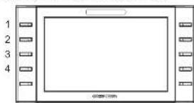
Press hard keys 1, 2, 3, and 4 on the left side of the touch screen display in sequence, twice (press 1, 2, 3, 4, 1, 2, 3, 4) within a 5-second period.
natural_image
Pure diagram of a rectangular frame with numbered corners and no text or symbolsThe main setup screen is displayed.

DO Learn More
Visit the website for additional information and the latest firmware updates. To learn more about this product, use a OR reader application on your mobile device to scan the OR image.
Cresbron Electronics
15 Volvo Drive, Rocklagh, NJ 37647 888.CRESTRON | www.crestron.com

CE As of the date of manufacture, the product has been leased and traded to comply with analytical order for CE marking.
Federal Communications Commission (FCC) Compliance Statement
The device complies with part 15 of the PCC Rules. Operation is subject to the following two conditions:
(1) The risks may be called her/fill, which is, and (2) that has been a triangular arrangement of cases. Training experience that may be involved in operation.
CAUTION: Changes or modifications not actively approved by the manufacturer responsible for compliance could be sold the user authority to acquire the equipment.
NOTE: This equipment has been heated and turned to comply with the limit for a China B. digital device, pursuant to the 15 of the FCC. Values. These limits are designed to provide reasonable protection against the initial market in a secondary installation. This equipment generates, uses and can receive radio frequency energy and, if not available and use in accordance with the instructions, may cause harmful interference to reduce communication costs. However, there is no guarantee that interference will not occur in particular installation.
If this equipment does cause harmful interference to reduce television reception, which can be determined by turning the equipment off and on. The user is encouraged to try to conduct the interference by one or more of the following measures:
- They are not clear as the moving areas.
- Increase the separation between the equipment and receiver. - Connect the equipment into an order on a virtual different from that to which the receiver is connected. - Consult the dealer or an operator and radio-TV technics on for help.
Industry Canada (10) Compliance Statement
CAN LICE 3 (P) NMB 2 (B)
The following table is provided in the image. The text in the source image is a stylistic or background line, not a placeholder for text. According to Rule 2, such lines must be ignored by the OCR result. Therefore, the corrected OCR text is:
[No text detected]
Dr. R. and D. C. C. C. C. C. C. C. C. C. C. C. C. C. C.
In our case, we can do by the United Financial Services company, Inc. (2001) and the Securities Services Company.
Brand : Crestron
Model : TSW-732-W-S
Category : Television