
CLX-1MC4 - Electric control module Crestron - Free user manual and instructions
Find the device manual for free CLX-1MC4 Crestron in PDF.


| Product Type | Control System Interface |
| Dimensions (W x H x D) | 8.4 x 1.7 x 6.0 inches |
| Weight | 2.5 lbs |
| Power Supply | 24V DC, 0.5A |
| Power Consumption | 12W max |
| Mounting | 1U rack-mountable |
| Control Interfaces | RS-232, IR, Ethernet |
| Audio/Video Switching | 4x1 HDMI or composite |
| Supported Protocols | Crestron RoomView, SNMP |
| Operating Temperature | 32°F to 104°F (0°C to 40°C) |
| Humidity | 10% to 90% non-condensing |
| Cleaning Instructions | Wipe with a dry, soft cloth |
| Safety Warnings | Do not expose to liquids or excessive heat |
| Spare Parts Availability | Contact Crestron authorized dealers |
| Repairability | Service by qualified technicians only |
| Brand | Crestron |
| Model | CLX-1MC4 |
Frequently Asked Questions - CLX-1MC4 Crestron
User questions about CLX-1MC4 Crestron
0 question about this device. Answer the ones you know or ask your own.
Ask a new question about this device
Download the instructions for your Electric control module in PDF format for free! Find your manual CLX-1MC4 - Crestron and take your electronic device back in hand. On this page are published all the documents necessary for the use of your device. CLX-1MC4 by Crestron.
USER MANUAL CLX-1MC4 Crestron
The Crestron ^® 1-feed, 4-motor terminal block and module (CLT-1MC4 and CLX-1MC4, respectively) are considered a single entity and must be used together. They ship separately to permit termination of the field wiring to the CLT-1MC4 prior to installation of the CLX-1MC4. They can be mounted in any Crestron Automation Enclosure (CAEN-Series Enclosures). The terminal block is designed to terminate the circuit feed (LINE and NEUTRAL) and distribute the controlled circuits (LOAD) to the motors. The module connects to the terminal block and controls four bidirectional motors. The maximum load is 10 Amps (1/2 HP) for any controlled circuit, limited to 16 amps total per module. The unit requires 120 Vac 50/60 Hz, 1 phase input voltage. An oversize heat sink dissipates heat efficiently. There are LEDs on the module to indicate communication to a Cresnet ^® network, input power to the module, and output power to the load.
Additional Resources
Visit the product page on the Crestron website (www.crestron.com) for additional information and the latest firmware updates. Use a QR reader application on your mobile device to scan the QR image.

CLT-1MC4

CLX-1MC4
Installation
WARNING: To avoid fire, shock, or death, turn off the power at the circuit breaker or fuse, and test that the power is off before wiring!
CAUTION: This equipment is for indoor use only and needs to be air cooled. Mount in a well-ventilated area. The ambient temperature must be 32^ F to 104^ F ( 0^ C to 40^ C). The relative humidity must be 0% to 90% (noncondensing).
NOTES: Observe the following points:
- This product must be installed and used in accordance with appropriate electrical codes and regulations.
• This product must be installed by a licensed electrician.
NOTE: Before using the CLX-1MC4, ensure the device is using the latest firmware. Check for the latest firmware for the CLX-1MC4 at www.crestron.com/firmware. Firmware is loaded onto the device using Crestron Toolbox™ software.
The terminal block is installed along the left side of single-wide enclosures and along the outside edges (left and right sides) of double-wide enclosures. The module is installed along the right side of single-wide enclosures and side-by-side in the center of double-wide enclosures. When installing modules and terminal blocks in a double-wide enclosure, be sure to invert units on the right side so that they can be properly wired. Refer to the illustrations when considering the location of terminal blocks and modules within an enclosure.
NOTE: The CLT-1MC4 and CLX-1MC4 must be installed into the lowest available spaces of the enclosure first and then continue toward the top of the enclosure.
Terminal Block and Module Locations (Single-Wide Enclosure)

Terminal Block and Module Locations (Double-Wide Enclosure)

NOTE: If an assembled UL ^® Listed panel is required, it can be obtained through Crestron's UL Listed panel shop. An assembled UL Listed panel includes complete in-factory system configuration and assembly by Crestron for an additional fee.
Terminal Block Installation and Field Wiring
Apply the supplied adhesive label before installing the terminal block. The adhesive label provides identification for each terminal in the terminal block and is designed to accommodate installation into the left or right side of the enclosure.
NOTE: Both left-side and right-side adhesive wiring labels are provided. The left-side labels are used in both single- and double-wide enclosures. The right-side labels are used only in double-wide enclosures.
- Remove the backing from the left- or right-side adhesive wiring label.
- Apply the adhesive label by aligning the holes in the label with the holes on the Crestron Automation Enclosure where the terminal block is to be mounted. The wiring label lies beneath the terminal block as shown in the following diagrams.
- Use the two supplied self-tapping Phillips pan head screws (8B x 1/4-inch length) to secure the terminal block to the Crestron Automation Enclosure.
CAUTION: The jumper on the white section of the terminal block ties the neutral in to the neutral out. These jumpers should never be removed.
NOTE: Use copper conductors only—rated 75°C or greater.
- Turn off the circuit breakers.
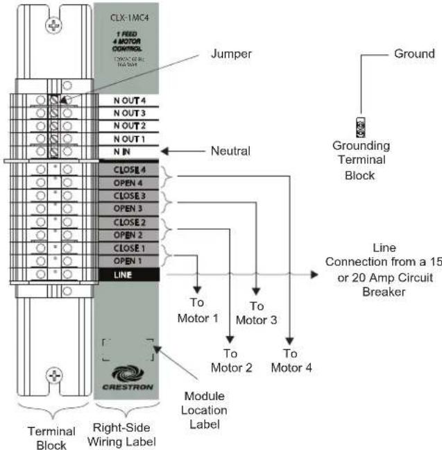
- Connect the circuit feed (LINE and NEUTRAL) and controlled circuit (LOAD) wires to the terminal block per the markings provided on the wiring label (as shown in the following diagrams). Terminal blocks accept one 14-10 AWG wire. Strip the wires to 1/2 in (13 mm). Tighten terminal blocks to 9 in-lbs.
NOTE: Only one motor may be wired per circuit.
- Terminate the ground wires at the grounding terminal blocks that are available in the enclosure. Tighten the grounding terminal blocks to 35 in-lbs (14–10 AWG), 40 in-lbs (8 AWG), or 45 in-lbs (6–4 AWG).
- Test the circuit for electrical faults by connecting LINE to OPEN 1. Switch on the circuit breaker, and check that it does not trip and that the load connected to OPEN 1 is receiving power. Switch off the circuit breaker, remove the connection between LINE and OPEN 1, and repeat this step, for CLOSE 1, and then sequentially for each OPEN and CLOSE motor connection.
Wiring the Terminal Block to the Food and Load(s) (Single-Wide and Left-Side Double-Wide Enclosures)

flowchart
graph TD
    A["Ground"] --> B["Grounding Terminal Block"]
    B --> C["To Motor 1"]
    C --> D["To Motor 2"]
    D --> E["To Motor 3"]
    E --> F["To Motor 4"]
    F --> G["Module Location Label"]
    G --> H["Left-Side Wiring Label"]
    H --> I["Terminal Block"]
    I --> J["Jumper"]
    K["CLX 1MC4"] --> L["OPEN 1"]
    K --> M["CLOSE 1"]
    K --> N["OPEN 2"]
    K --> O["CLOSE 2"]
    K --> P["OPEN 3"]
    K --> Q["CLOSE 3"]
    K --> R["OPEN 4"]
    K --> S["CLOSE 4"]
    T["N IN"] --> U["N OUT 1"]
    T --> V["N OUT 2"]
    T --> W["N OUT 3"]
    T --> X["N OUT 4"]
Wiring the Terminal Block to the Feed and Load(s) (Right-Side Double-Wide Enclosures)
Module Installation
CAUTION: The module contains electrostatic-sensitive devices (ESDs); the unit must be handled from the metal chassis. Do not touch the PC board or components.
Install the module after the terminal block is installed and the enclosure has been completely wired.
- Use the four supplied self-tapping Phillips pan head screws (8B x 1/4-inch length) to secure the module to the enclosure.
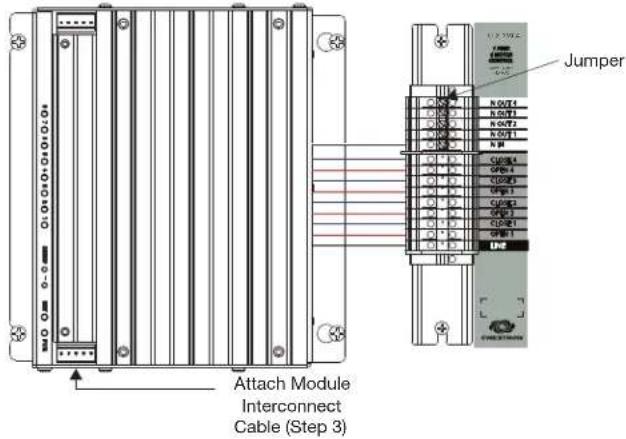
- As shown in the wiring diagram, connect the wires from the module to the terminal block. Each wire exits the module directly in line with, and is the same color as, the terminal to which it should be connected. Wires are prestripped to 1/2 in (13 mm). Tighten to 9 in-lbs.
- If the module is being installed above another module within the enclosure, attach the supplied module-interconnect cable to the two modules. The illustration that follows shows the area within a double-wide enclosure where the corners of four modules meet.
NOTE: One wire on the module-interconnect cable may be a different color from the rest. The color has no bearing on its orientation during installation.
Use the Module Interconnect Cable to Wire Module to Module.

- Turn on the circuit breakers and verify that the green PWR LED on the module lights, that the breakers do not trip, and that power is delivered to the loads.
NOTE: Power must be supplied to LINE for the module to communicate with the control system or any of the circuits to operate.
Wiring the Terminal Block to the Module

Wiring Diagram of the Terminal Block to the Module (Right Side Double-Wide Enclosures)
This product is Listed to applicable UL Standards and requirements by Underwriters Laboratories Inc.

The product warranty can be found at www.crestron.com/warranty.
The specific patents that cover Crestron products are listed at patents.crestron.com.
Certain Crestron products contain open source software. For specific information, please visit www.crestron.com/opensource.
Crestron, the Crestron logo, Cresnet, and Crestron Toolbox are either trademarks or registered trademarks of Crestron Electronics, Inc. in the United States and/or other countries. UL and the UL logo are either trademarks or registered trademarks of Underwriters Laboratories, Inc. in the United States and/or other countries. Other trademarks, registered trademarks, and trade names may be used in this document to refer to either the entities claiming the marks and names or their products. Crestron disclaims any proprietary interest in the marks and names of others. Crestron is not responsible for errors in typography or photography.
This document was written by the Technical Publications department at Crestron. ©2015 Crestron Electronics, Inc.
Crestron Electronics, Inc. Installation Guide - DOC. 5991D 15 Volvo Drive Rockleigh, NJ 07647 (2002073) Tel: 888 CRESTRON 12-15
Fax: 201.767.7576 Specifications subject to www.crestron.com change without notice.
Brand : Crestron
Model : CLX-1MC4
Category : Electric control module