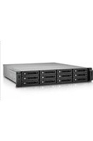
REXP-1200U-RP - Disk array QNAP - Free user manual and instructions
Find the device manual for free REXP-1200U-RP QNAP in PDF.


| Product Type | Storage Expansion Enclosure (Disk Array) |
| Model | REXP-1200U-RP |
| Brand | QNAP |
| Form Factor | 2U Rackmount |
| Drive Bays | 12 x 3.5-inch or 2.5-inch SAS/SATA (hot-swappable) |
| Interface | 2 x Mini-SAS HD (SFF-8644) for host connection |
| Expansion Capability | Up to 8 units daisy-chained via SAS |
| Power Supply | Redundant 300W (80+ Bronze) hot-swappable |
| Cooling | 3 x 60mm hot-swappable fans |
| Dimensions (HxWxD) | 88 x 482 x 534 mm (3.46 x 18.98 x 21.02 in) |
| Weight | 12.5 kg (27.56 lbs) without drives |
| Operating Temperature | 0°C to 40°C (32°F to 104°F) |
| Humidity | 5% to 95% non-condensing |
| Power Consumption | ~90W typical (without drives) |
| Management | Via QNAP QTS or QES (screen and buttons on front panel) |
| LED Indicators | Status, drive, fan, temperature, power |
| Supported Drives | SAS 12Gbps / SATA 6Gbps HDD/SSD |
| Maximum Capacity | Depends on drive size (up to 192TB with 16TB drives) |
| Safety Certifications | CE, FCC, VCCI, BSMI, UL, etc. |
| Warranty | 2 years (extendable) |
| Maintenance | Clean with dry cloth; avoid liquid cleaners |
| Repairability | Hot-swappable PSU, fans, and drives; replaceable modules |
| Spare Parts | Contact QNAP or authorized resellers for replacement modules |
Frequently Asked Questions - REXP-1200U-RP QNAP
User questions about REXP-1200U-RP QNAP
0 question about this device. Answer the ones you know or ask your own.
Ask a new question about this device
Download the instructions for your Disk array in PDF format for free! Find your manual REXP-1200U-RP - QNAP and take your electronic device back in hand. On this page are published all the documents necessary for the use of your device. REXP-1200U-RP by QNAP.
USER MANUAL REXP-1200U-RP QNAP
Safety information....3
2. Introduction
NAS model categorization....6
Repair requirements.... 10
Resources....10
3. Category A NAS Models
Disassembling the TS-453E....12
Reassembling the TS-453E....24
TS-453E components and screws.... 36
4. Category B NAS Models
Disassembling the TS-AI642....39
Reassembling the TS-AI642....48
TS-AI642 components and screws....57
5. Category C NAS Models
Disassembling the TVS-h874T....60
Reassembling the TVS-h874T....78
TVS-h874T components and screws....95
6. Category D NAS Models
Disassembling the TVS-h1288X....98
Reassembling the TVS-h1288X....119
TVS-h1288X components and screws.... 141
7. Category E NAS Models
Disassembling the TS-h1677AXU-RP 145
Reassembling the TS-h1677AXU-RP 158
TS-h1677AXU-RP components and screws....171
8. Glossary
air shroud....174
backplane....174
central processing unit (CPU)....174
circuit board....174
CPU fan....174
drive cage....174
drive tray....174
fan duct....174
flat head screw....174
heatsink....175
LCD display module....175
mounting holes....175
pan head screw....175
Phillips screwdriver....175
positioning holes....175
positioning posts.... 175
power supply cage....175
power supply unit (PSU)....175
riser card....175
self-tapping screw....176
system board.... 176
system fan....176
thumb screw.... 176
1. Important Information
Original Packaging
Please keep the original packaging and packaging materials. If you want to return the product or send it for repairs, please use the original packaging to avoid damage.
QNAP reserves the right not to provide a refund or warranty service for products that are damaged due to improper packaging.
Hardware Defects
If your QNAP product has hardware defects, return the product to QNAP or a QNAP-authorized service center for maintenance or replacement. Any attempt to repair or perform maintenance procedures on the product by you or an unauthorized third party invalidates the warranty.
QNAP is not responsible for any damage or data loss caused by unauthorized modifications and installation of unsupported third-party applications.
For details, see the QNAP Warranty Terms and Conditions.
Safety information
The following instructions help ensure personal safety and environmental safety. Read these instructions carefully before performing any operation.
General Instructions
- The device should be stored in a secure location with restricted access, controlled through the use of a tool, lock and key, or any means of security.
- Only qualified, skilled, and authorized persons with knowledge of all restrictions, safety precautions, and installation and maintenance procedures should have physical access to the device.

WARNING

To avoid potential injury or damage to components, ensure that the drives and other internal system components have cooled before touching them.

Observe electrostatic discharge (ESD) procedures to avoid potential injury or damage to components.
Power

WARNING

To reduce the risk of fire or electric shock, ensure that you only connect the power cord to a properly grounded electrical outlet.
Devices with redundant power supply may have one or more power supply unit (PSU) cords. To avoid serious injuries, a trained service technician must disconnect all PSU cords from the device before installing or replacing system components.
Moving Parts

WARNING

Moving fan blades: Keep your body parts away from any moving fan blades while the device is connected to a power source.

Moving components: Keep your body parts away from any other moving components.
The device is not suitable for use in locations where children are likely to be present.
System Battery

WARNING

INGESTION HAZARD
- This product may contain a button battery.
- Keep batteries out of reach of children.
- If swallowed, a lithium button battery can cause severe or fatal injuries within 2 hours.
- If you think batteries may have been swallowed or placed inside any part of the body, seek immediate medical attention.
- To avoid potential battery explosion, causing injury or damage to components, ensure that you replace the existing battery with a battery of the same type.
- Dispose of used batteries properly according to local regulations or the instructions of the battery manufacturer.
- Even used batteries may cause severe injury or death.
- Call a local poison control center for treatment information.
- For information on the type and voltage of the button battery in your device, please see the hardware specification table.
• Non-rechargeable batteries are not to be recharged. - Do not force discharge, recharge, disassemble, heat, or incinerate. Doing so may result in injury due to venting, leakage, or explosion resulting in chemical burns.
- Ensure the batteries are installed correctly according to polarity (+ and -).
- Do not mix old and new batteries, or different brands or types of batteries, such as alkaline, carbon-zinc, or rechargeable batteries.
- Remove and immediately recycle or dispose of batteries from equipment not used for an extended period of time according to local regulations.
- Always completely secure the battery compartment. If the battery compartment does not close securely, stop using the product, remove the batteries, and keep them away from children.
Rail Kits
Rackmount models may require rail kits for installation onto a server rack or cabinet.
To ensure equipment and personal safety, please carefully read the installation instructions for your rail kit before you install the rail kit and mount your device.
To check if your device is a rackmount unit, see the hardware specification table.

WARNING
- When the rail kit is installed on the server rack, do not fully extend and unlatch the rails except when mounting or unmounting a device.
• Leaving the rails fully extended out and unlatched may cause heavy equipment to fall. This can cause equipment damage and severe or even fatal injuries. - Before you prepare the rails for device mounting or unmounting, please carefully read and ensure you understand the installation instructions.
- Do not place any objects or add any extra load onto the device or rails when mounting or unmounting a device.
- When mounting a device, slide the device all the way into the server rack to fully latch the rails and secure the device to the server rack.
2. Introduction
This repair manual provides technical instructions for disassembling and reassembling various NAS models, allowing users to replace major components for their devices.
These instructions are intended for individuals with sufficient hardware knowledge and experience to repair electronic devices. We recommend reading this manual carefully to understand the procedure and the required tools. Only proceed if you feel comfortable performing the tasks instructed in this manual.
Important
Failure to follow the instructions may damage the components or affect the functionality of your device. Damages caused by self-repair are not covered by QNAP warranty service.
NAS model categorization
QNAP NAS models can be divided into the following categories based on their mechanical design.
Important
These model lists are not exhaustive. If your model is not listed, we recommend following the given criteria to classify your model.
Category A
NAS models in this category are small tower NAS models. The power button and LEDs are located on the left side of the front panel.

Representative model: TS-453E
Similar models: TS-216G, TS-253E, TS-431X3, TS-431KX, TS-431K, TS-433
Category B
NAS models in this category are small or medium tower NAS models that have a sliding front cover protecting their drive bays.

Representative model: TS-AI642
Similar models: TS-264, TS-464, TS-664, TS-262, TS-462, TS-432X, TS-632X
Category C
NAS models in this category are medium or large tower NAS models. Many models in this category have an LCD panel above the drive bays.

Representative model: TS-h874T
Similar models: TS-473A, TS-673A, TS-873A, TVS-472XT, TVS-672XT, TVS-872XT, TVS-h474, TVS-h674, TVS-h874, TVS-h674T, TS-832PX, TVS-675,
Category D
NAS models in this category are large tower NAS models that have 2.5-inch drive bays.
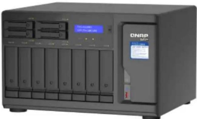
Representative model: TVS-h1288X
Similar models: TS-855X, TS-1655, TS-h886, TVS-h1688X
Category E
NAS models in this category are rackmount NAS models, which are designed to be mounted on server racks. Rackmount NAS models are usually larger than tower NAS models.

Representative model: TS-h1677AXU-RP
Similar models: TS-873AeU, TS-873AeU-RP, TS-832PXU, TS-832PXU-RP, TS-855eU, TS-855eU-RP, TS-1232PXU-RP, TS-877XU-RP, TS-h1277XU-RP, TS-1283XU-RP, TS-h1277AXU-RP
Categorization criteria and flow chart
To categorize a NAS model, follow these steps:
- Is your NAS a rackmount model?
• Yes: It belongs to Category E.
- No: Go to the next step.
- Does your NAS have a sliding front cover that protects the drive bays?
• Yes: It belongs to Category B.
• No: Go to the next step.
- Is the power button of your NAS located on the left side of the front panel?
• Yes: It belongs to Category A.
• No: Go to the next step.
- Does your NAS have 2.5-inch drive bays?
• Yes: It belongs to Category D.
• No: It belongs to Category C.
![graph TD A["Start"] --> B{Rackmount?} B -->|Yes| C["Category E TS-h1677AXU-RP"] B -->|No| D{Front cover?} D -->|Yes| E["Category B TS-AI642"] D -->|No| F{Power button on the left?} F -->|Yes| G["Category A TS-453E"] F -->|No| H{2.5-inch drive bays?} H -->|Yes| I["Category D TVS-h1288X"] H -->|No| J[…](/content/2026/05/1074985/images/be4e6fd84c4f8a375ba78e48f83f000473fcaf72568d7a99ab688ee89f48ec5c.jpg)
Repair requirements
| Category Item | |
| Environment • Room temperature: 0°C to 40°C (32°F to 104°F)Non-condensing relative humidity: 5% to 95%Wet-bulb temperature: 27°C (80.6°F)Flat, anti-static surface without exposure to direct sunlight, liquids, or chemicals | |
| Tools • Anti-static wrist strapPhillips #2 screwdriverPhillips #1 screwdriverSmall cutting pliersNoteSome internal cables may be bound together or bound to a part of a component with a cable tie. Some cable connections may also be glued for stability. To cut and remove the cable ties or glue without damaging the internal components and parts, use a small pair of cutting pliers very carefully. |
Resources
QNAP provides the following resources:
| Resource URL | |
| Self-Repair Portal https://www.qnap.com/go/service/self-repair | |
| Documentation https://download.qnap.com | |
| Compatibility List https://www.qnap.com/compatibility | |
| Service Portal https://service.qnap.com | |
| Product Support Status https://www.qnap.com/go/product/eol.php | |
| Downloads https://download.qnap.com | |
| Community Forum https://forum.qnap.com | |
| QNAP Accessories Store https://shop.qnap.com | |
3. Category A NAS Models
This chapter uses the TS-453E as the representative NAS model for category A. The disassembly and reassembly instructions, and the list of components and screws, are based on the representative model.
For details on category A NAS models, see NAS model categorization.
Note
While all NAS models in the same category share the same general structural design, different models may have certain differences in their parts and components in terms of size, quantity, and other specifications. For non-representative models in this category, please use the following topics as a point of reference.
Disassembling the TS-453E
Before you start, make sure you read the Repair requirements.
Warning
- Observe electrostatic discharge (ESD) procedures to avoid damage to components.

Moving fan blades: Keep your hands and other body parts away from moving fan blades.

Other moving components: Keep your hands and other body parts away from other moving components.
- Power off the NAS.
- Disconnect the power cord from the electrical outlet.
-
Disconnect all cables and external attachments.
-
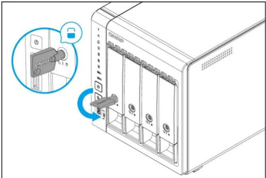
Unlock the drive trays.
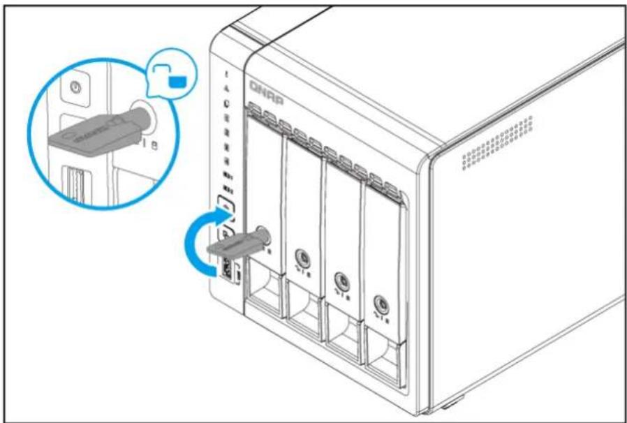
- Remove all drive trays.
Important
Remember the number of each drive. Each drive will need to be returned to its original bay.

- Remove the case cover.
a.Position the NAS on its left side.
b. Remove the screws on the rear panel.

Note
- The pan head M3x5 screws require a Phillips #1 screwdriver.
- A torque of 2.75 kgf.cm (2.39 lbf.in) ± 0.25 kgf.cm (0.22 lbf.in) is recommended for electric screwdrivers.
c.Slide the cover back.
d.Lift the cover until it is completely detached from the chassis.

7. Remove the drive cage.
a. Remove the screws that secure the drive cage to the system board.

Note
- The flat head M3x4 screws require a Phillips #2 screwdriver.
- A torque of 5 kgf.cm (4.34 lbf.in) ± 0.5 kgf.cm (0.43 lbf.in) is recommended for electric screwdrivers.
b.Lift the drive cage until it is completely detached.
Note
The riser card and the backplane are screwed to the drive cage. Detaching the drive cage also detaches the riser card and the backplane from their slots on the system board.
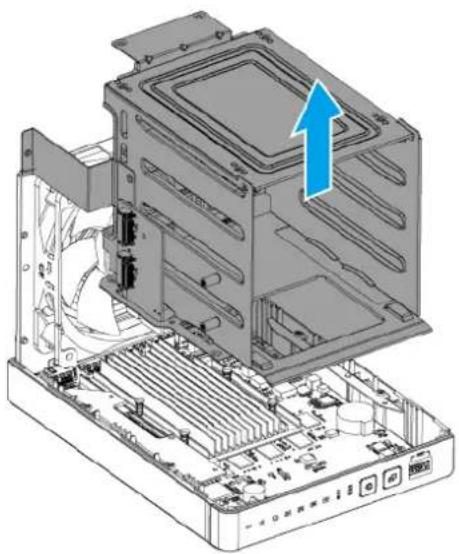
-
Position the drive cage on its bottom side by rotating clockwise 90 degrees.
-
Remove M.2 SSDs from the riser card.
Note
This step is necessary if there are M.2 SSDs installed on the riser card and you want to detach the riser card from the drive cage.
a. Remove the screw that secures the M.2 SSD to the drive cage.
Note
- The pan head M2.5x3 screw requires a Phillips #2 screwdriver.
- A torque of 3 kgf.cm (2.60 lbf.in) ± 0.5 kgf.cm (0.43 lbf.in) is recommended for electric screwdrivers.
b. Remove the M.2 SSD.

c. Remove the other M.2 SSD.
- Remove the riser card.
Warning
Do not touch the components on the circuit board or allow the components to come into direct contact with metallic objects. Doing so may cause damage.
a. Remove the screw that secures the riser card to the drive cage.
Note
- The pan head M3x5 screw requires a Phillips #2 screwdriver.
- A torque of 7 kgf.cm (6.08 lbf.in) ± 0.5 kgf.cm (0.43 lbf.in) is recommended for electric screwdrivers.
b. Remove the riser card.
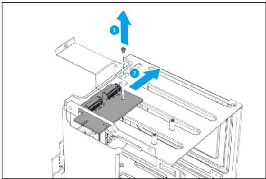
- Remove the drive backplane.
Warning
Do not touch the components on the circuit board or allow the components to come into direct contact with metallic objects. Doing so may cause damage.
a. Remove the screws that secure the backplane to the drive cage.
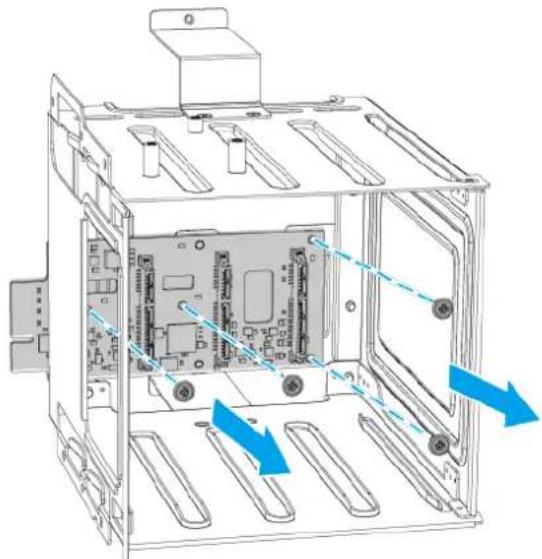
Note
- The pan head M3x5 screws require a Phillips #2 screwdriver.
- A torque of 7 kgf.cm (6.08 lbf.in) ± 0.5 kgf.cm (0.43 lbf.in) is recommended for electric screwdrivers.
b. Carefully hold both ends of the backplane.
c. Lightly push the left end back while lifting the right end off the drive cage surface.
d. Carefully remove the backplane from the drive cage.
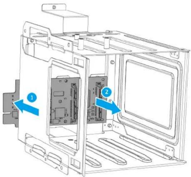
- Remove the chassis.
Note
The chassis consists of the system board tray and the rear panel as a single component.
a. Remove the screws that secure the chassis to the left panel.

Note
- The pan head self-tapping D3x6 screws require a Phillips #2 screwdriver.
- A torque of 5 kgf.cm (4.34 lbf.in) ± 0.5 kgf.cm (0.43 lbf.in) is recommended for electric screwdrivers.
b. Tilt the rear end of the chassis up by about 20 degrees.
c.Lift the chassis out of the left panel.

13. Remove the system fan.
a.Disconnect the fan cable from the system board.

b. Remove the screws that secure the fan to the rear panel.

Note
- The flat head self-tapping M5x10 screws require a Phillips #2 screwdriver.
- A torque of 5 kgf.cm (4.34 lbf.in) ± 0.5 kgf.cm (0.43 lbf.in) is recommended for electric screwdrivers.
c.Remove the fan.
Important
Remember which side of the fan is attached. To ensure proper cooling, the correct side must be reattached so that the airflow is directed out of the rear panel. There may be an arrow on the side of the fan that indicates the airflow direction.

- Remove the system board.
Warning
Do not touch the components on the circuit board or allow the components to come into direct contact with metallic objects. Doing so may cause damage.
a. Remove the screws that secure the HDMI ports on the system board to the rear panel.
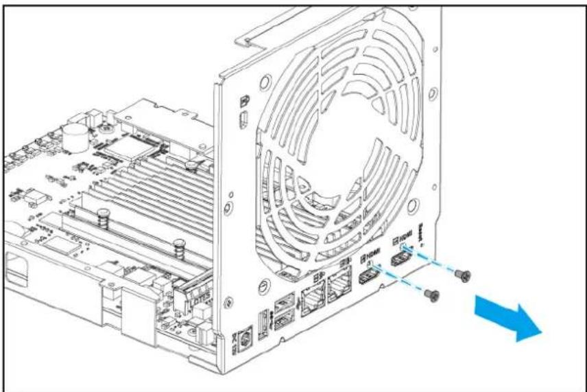
Note
- The flat head M2x4 screws require a Phillips #1 screwdriver.
- A torque of 2 kgf.cm (1.74 lbf.in) ± 0.5 kgf.cm (0.43 lbf.in) is recommended for electric screwdrivers.
b. Remove the screws that secure the system board to the chassis.

Note
- The pan head M3x5 screws require a Phillips #2 screwdriver.
- A torque of 7 kgf.cm (6.08 lbf.in) ± 0.5 kgf.cm (0.43 lbf.in) is recommended for electric screwdrivers.
c.Lift the system board by approximately 3 mm.
d. Slide the system board out of the chassis.

Reassembling the TS-453E
Before you start, make sure you read the Repair requirements.
Warning
- Observe electrostatic discharge (ESD) procedures to avoid damage to components.

Moving fan blades: Keep your hands and other body parts away from moving fan blades.
Other moving components: Keep your hands and other body parts away from other moving components.
- Install the system board.
Warning
Do not touch the components on the circuit board or allow the components to come into direct contact with metallic objects. Doing so may cause damage.
a.Slide the system board into the chassis.
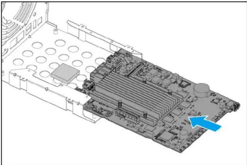
b. Align the mounting holes on the system board to the screw holes on the chassis.
c. Attach the screws that secure the system board to the chassis.

Note
- The pan head M3x5 screws require a Phillips #2 screwdriver.
- A torque of 7 kgf.cm (6.08 lbf.in) ± 0.5 kgf.cm (0.43 lbf.in) is recommended for electric screwdrivers.
d. Attach the screws that secure the HDMI ports on the system board to the rear panel.

Note
- The flat head M2x4 screws require a Phillips #1 screwdriver.
-
A torque of 2 kgf.cm (1.74 lbf.in) ± 0.5 kgf.cm (0.43 lbf.in) is recommended for electric screwdrivers.
-
Install the system fan.
a. Align the screw holes on the fan to the screw holes on the rear panel.
Important
To ensure proper cooling, the correct side of the fan must be reattached so that the airflow is directed out of the rear panel. There may be an arrow on the side of the fan that indicates the airflow direction.
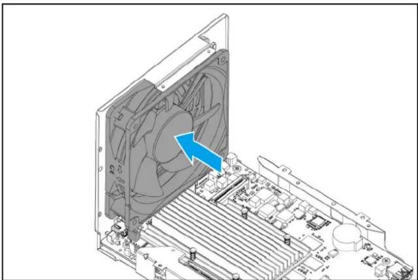
b. Attach the screws that secure the fan to the rear panel.

Note
- The flat head self-tapping M5x10 screws require a Phillips #2 screwdriver.
- A torque of 5 kgf.cm (4.34 lbf.in) ± 0.5 kgf.cm (0.43 lbf.in) is recommended for electric screwdrivers.
c. Attach the fan cable to the system board.

- Attach the chassis to the left panel.
a. Insert the chassis into the front of the left panel at an angle of around 20 degrees.
b. Ensure the USB port on the system board is inserted into the USB port hole on the left panel.
c. Place the chassis fully into the left panel.
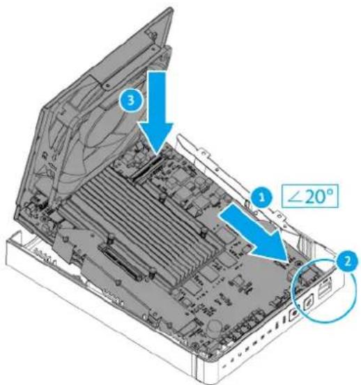
d. Attach the screws that secure the chassis to the left panel.
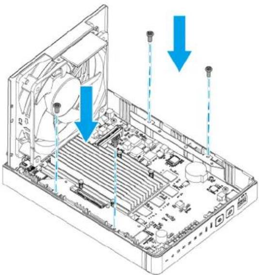
Note
- The pan head self-tapping D3x6 screws require a Phillips #2 screwdriver.
- A torque of 5 kgf.cm (4.34 lbf.in) ± 0.5 kgf.cm (0.43 lbf.in) is recommended for electric screwdrivers.
- Attach the backplane to the drive cage.
Warning
Do not touch the components on the circuit board or allow the components to come into direct contact with metallic objects. Doing so may cause damage.
a. Carefully insert the connector end of the backplane into the hole at the back of the drive cage.
b. Align the holes on the backplane to the positioning posts and screw holes on the drive cage.

c. Place the backplane on the drive cage so that the positioning posts keep the backplane in place.
d. Attach the screws that secure the backplane to the drive cage.

Note
- The pan head M3x5 screws require a Phillips #2 screwdriver.
-
A torque of 7 kgf.cm (6.08 lbf.in) ± 0.5 kgf.cm (0.43 lbf.in) is recommended for electric screwdrivers.
-
Attach the riser card to the drive cage.
Warning
Do not touch the components on the circuit board or allow the components to come into direct contact with metallic objects. Doing so may cause damage.
a. Insert the connector end of the riser card into the hole on the drive cage.
b. Align the screw hole on the riser card to the screw hole on the drive cage.
c. Attach the screw that secures the riser card to the drive cage.

Note
- The pan head M3x5 screw requires a Phillips #2 screwdriver.
- A torque of 7 kgf.cm (6.08 lbf.in) ± 0.5 kgf.cm (0.43 lbf.in) is recommended for electric screwdrivers.
6.Optional: Install M.2 SSDs on the riser card.
a. Insert the M.2 SSD into the slot.
b. Attach the screw.
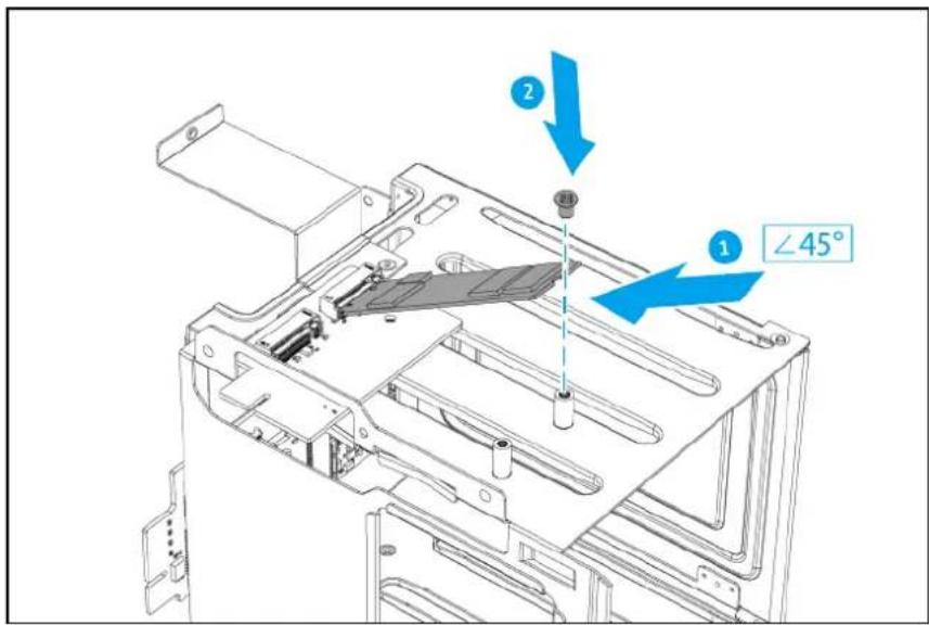
Note
- The pan head M2.5x3 screw requires a Phillips #2 screwdriver.
- A torque of 3 kgf.cm (2.60 lbf.in) ± 0.5 kgf.cm (0.43 lbf.in) is recommended for electric screwdrivers.
c.Optional: Install an additional M.2 SSD.
- Attach the drive cage.
a. Align the connectors on the riser card and backplane to the slots on the system board.
b. Firmly push down on the drive cage so that the riser card and backplane connectors are inserted into the slots on the system board.

c. Attach the screws to secure the drive cage to the chassis.

Note
- The flat head M3x4 screws require a Phillips #2 screwdriver.
-
A torque of 5 kgf.cm (4.34 lbf.in) ± 0.5 kgf.cm (0.43 lbf.in) is recommended for electric screwdrivers.
-
Attach the case cover.
a. Place the cover on the device.
b.Slide the cover forward.
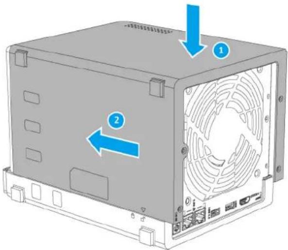
c. Attach the screws that secure the case cover to the rear panel.

Note
- The pan head M3x5 screws require a Phillips #1 screwdriver.
- A torque of 2.75 kgf.cm (2.39 lbf.in) ± 0.25 kgf.cm (0.22 lbf.in) is recommended for electric screwdrivers.
d. Place the NAS in its normal upright position.
9.Slide each drive tray back into the NAS.
Important
Each drive must be returned to its original bay.

10.Optional: Lock the trays.
TS-453E components and screws
Note
The information presented here apply only to the representative model of the NAS category. While all models within a NAS category have the same general structural design, their components and screws may differ in size, quantity, and other specifications.
Important
Recommended torque values are provided for electric screwdrivers. To avoid damage to the screw or component, the actual torque setting should not exceed ± 0.5 kgf.cm (0.43 lbf.in) of the recommended value, unless specified otherwise.

| No. | Component (Quantity) | Screw Type (Quantity) | Screwdriver (Torque) | Attached To |
| 1 | Left panel (1) | --- | ||
| 2 | System board (1) | Pan head M3x5 (4) | Phillips #2 (7 kgf.cm / 6.08 lbf.in) | Chassis |
| - | HDMI ports on system board (2) | Flat head M2x4 (1 x 2 = 2) | Phillips #1 (2 kgf.cm / 1.74 lbf.in) | Chassis (Rear panel) |
| No. Component (Quantity) | Screw Type (Quantity) | Screwdriver (Torque) | Attached To |
| 3 Chassis(1) | Pan headSelf-tapping D3x6(4) | Phillips #2(5 kgf.cm / 4.34 lbf.in) | Left panel |
| 4 Drive tray (3.5-inch)(4) | --- | ||
| 5 Backplane(1) | Pan headM3x5(4) | Phillips #2(7 kgf.cm / 6.08 lbf.in) | Drive cage |
| 6 Drive cage(1) | Flat headM3x4(8) | Phillips #2(5 kgf.cm / 4.34 lbf.in) | Chassis |
| 7 Riser card(1) | Pan headM3x5(1) | Phillips #2(7 kgf.cm / 6.08 lbf.in) | Drive cage |
| 8 System fan(1) | Flat headSelf-tapping M5x10(4) | Phillips #2(5 kgf.cm / 4.34 lbf.in) | Chassis(Rear panel) |
| 9 Drive tray key(2) | --- | ||
| 10 Case cover(1) | Pan headM3x5(4) | Phillips #1(2.75 kgf.cm / 2.39 lbf.in)ImportantTo avoid damage to these screws, the torque setting should not exceed ± 0.25kgf.cm (0.22 lbf.in) of the recommended value. | Chassis(Rear panel) |
Optional Components
These components are not included with the original NAS but may be installed by the user.
| Component (Quantity) | Screw Type (Quantity) | Screwdriver (Torque) | Attached To |
| M.2 SSD(2 maximum, not included with original NAS) | Pan headM2.5x3(2, included with original NAS) | Phillips #2(3 kgf.cm / 2.60 lbf.in) | Inserted into slot on riser card, and then secured to the drive cage with a screw. |
4. Category B NAS Models
This chapter uses the TS-AI642 as the representative NAS model for category B. The disassembly and reassembly instructions, and the list of components and screws, are based on the representative model.
For details on category B NAS models, see NAS model categorization.
Note
While all NAS models in the same category share the same general structural design, different models may have certain differences in their parts and components in terms of size, quantity, and other specifications. For non-representative models in this category, please use the following topics as a point of reference.
Disassembling the TS-AI642
Before you start, make sure you read the Repair requirements.
Warning
- Observe electrostatic discharge (ESD) procedures to avoid damage to components.

Moving fan blades: Keep your hands and other body parts away from moving fan blades.

Other moving components: Keep your hands and other body parts away from other moving components.
- Power off the NAS.
- Disconnect the power cord from the electrical outlet.
- Disconnect all cables and external attachments.
- Remove the front cover.
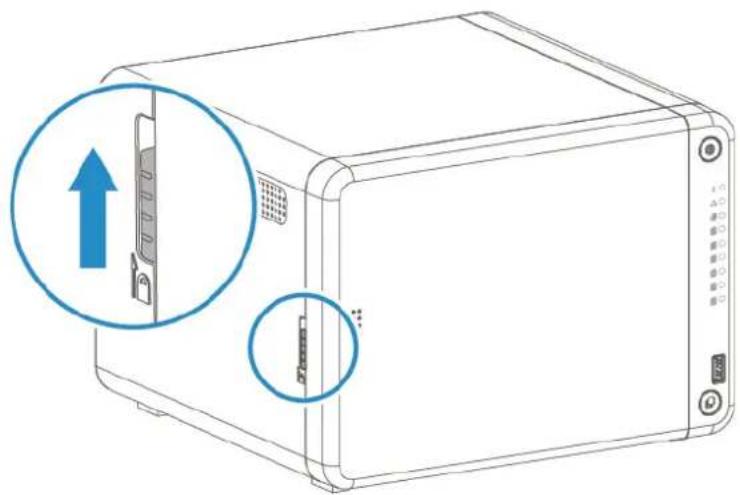
a. Locate the locking mechanism on the left side of the device.
b.Slide the lock up to release the front cover.
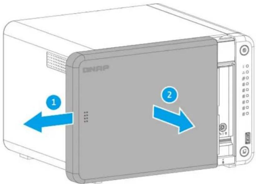
c.Slide the front cover to the left and then pull.
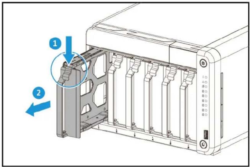
5. Remove all drive trays.
Important
Remember the number of each drive. Each drive will need to be returned to its original bay.
6. Remove the case cover.
a. Remove the screws that secure the case cover to the chassis.

Note
- The pan head M3x5 screws require a Phillips #1 screwdriver.
- A torque of 2.75 kgf.cm (2.39 lbf.in) ± 0.25 kgf.cm (0.22 lbf.in) is recommended for electric screwdrivers.
b.Slide the case cover back.
c.Slide the case cover to the left to detach it from the chassis.

- Remove the system fans.
a.Disconnect the fan cables from the backplane.
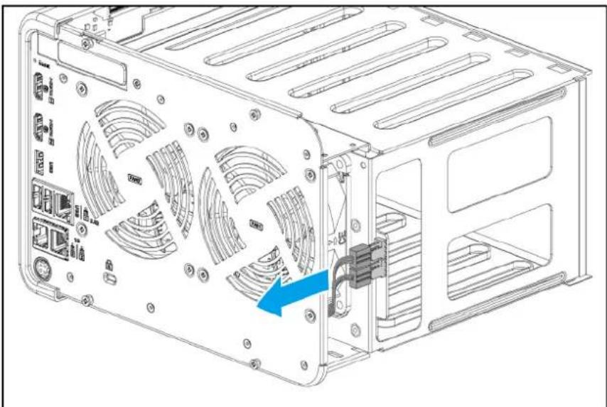
b. Remove the screws that secure the fans to the rear panel.
Note
- The flat head self-tapping M5x10 screws require a Phillips #2 screwdriver.
- A torque of 5 kgf.cm (4.34 lbf.in) ± 0.5 kgf.cm (0.43 lbf.in) is recommended for electric screwdrivers.
c. Remove the fans.
Important
Remember which side of the fans is attached. To ensure proper cooling, the correct side must be reattached so that the airflow is directed out of the rear panel. There may be an arrow on the side of the fans that indicates the airflow direction.

- Remove the chassis.
a.Position the NAS on its right side.
b. Remove the screws that secure the chassis to the right panel.
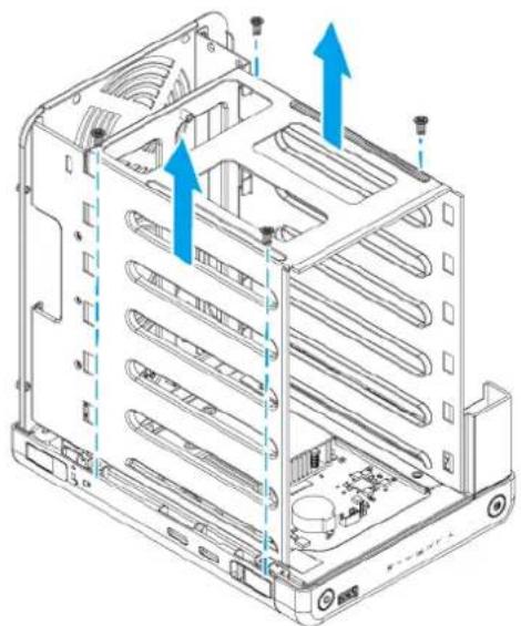
Note
- The flat head D3x6 screws require a Phillips #2 screwdriver.
- A torque of 5 kgf.cm (4.34 lbf.in) ± 0.5 kgf.cm (0.43 lbf.in) is recommended for electric screwdrivers.
c.Tilt the rear end of the chassis up by about 20 degrees.
d. Lift the chassis out of the right panel.
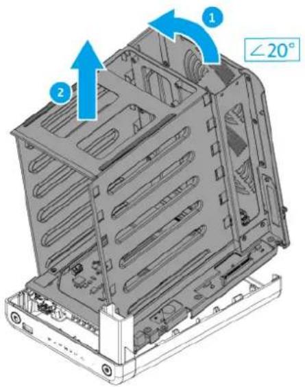
- Remove the drive backplane.
Warning
Do not touch the components on the circuit board or allow the components to come into direct contact with metallic objects. Doing so may cause damage.
a. Remove the screws that secure the backplane to the drive cage.
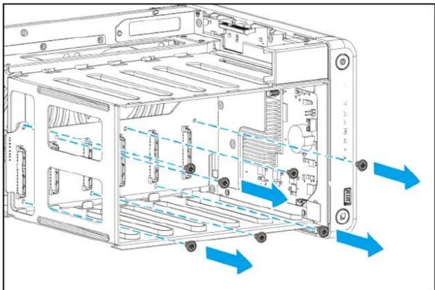
Note
- The pan head M3x5 screws require a Phillips #2 screwdriver.
- A torque of 7 kgf.cm (6.08 lbf.in) ± 0.5 kgf.cm (0.43 lbf.in) is recommended for electric screwdrivers.
b.Pull the backplane to the left to detach it from the system board.
c. Make sure the connector on the backplane is out of the slot on the system board.
d.Carefully remove the backplane from the drive cage.

- Remove the system board.
Warning
Do not touch the components on the circuit board or allow the components to come into direct contact with metallic objects. Doing so may cause damage.
a. Remove the screws that secure the system board to the chassis.

Note
- The pan head M3x5 screws require a Phillips #2 screwdriver.
- A torque of 7 kgf.cm (6.08 lbf.in) ± 0.5 kgf.cm (0.43 lbf.in) is recommended for electric screwdrivers.
b. Remove the screws that secure the HDMI ports on the system board to the rear panel.

Note
- The flat head M2x4 screws require a Phillips #1 screwdriver.
- A torque of 2 kgf.cm (1.74 lbf.in) ± 0.5 kgf.cm (0.43 lbf.in) is recommended for electric screwdrivers.
c. Detach the adhesive foil from the system board.

d. Carefully pull out the system board from the chassis.
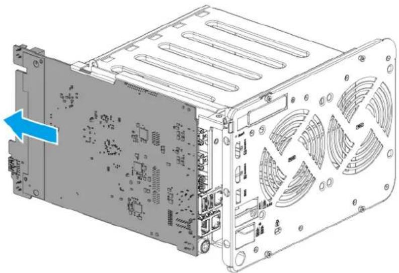
Reassembling the TS-AI642
Before you start, make sure you read the Repair requirements.
Warning
- Observe electrostatic discharge (ESD) procedures to avoid damage to components.
Moving fan blades: Keep your hands and other body parts away from moving fan blades.

Other moving components: Keep your hands and other body parts away from other moving components.
- Install the system board.
Warning
Do not touch the components on the circuit board or allow the components to come into direct contact with metallic objects. Doing so may cause damage.
a. Make sure the ports on the system board are inserted into the port holes in the rear panel.
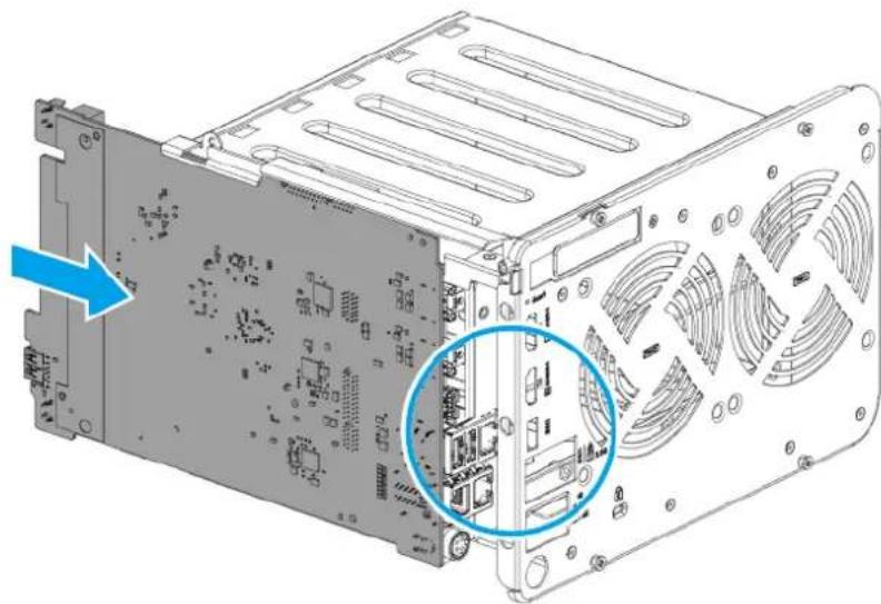
b.Slide the system board into the chassis.
c. Attach the adhesive foil to the system board.
Note
Make sure the foil is attached within the boundaries of the attachment area on the system board. If any part of the foil is outside the boundaries, it could cause a short circuit on the system board.

d. Align the mounting holes on the system board to the screw holes on the chassis.
e.Attach the screws that secure the HDMI ports on the system board to the rear panel.
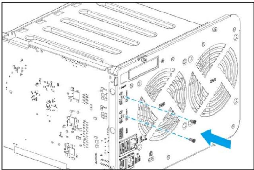
Note
- The flat head M2x4 screws require a Phillips #1 screwdriver.
- A torque of 2 kgf.cm (1.74 lbf.in) ± 0.5 kgf.cm (0.43 lbf.in) is recommended for electric screwdrivers.
f. Attach the screws that secure the system board to the chassis.
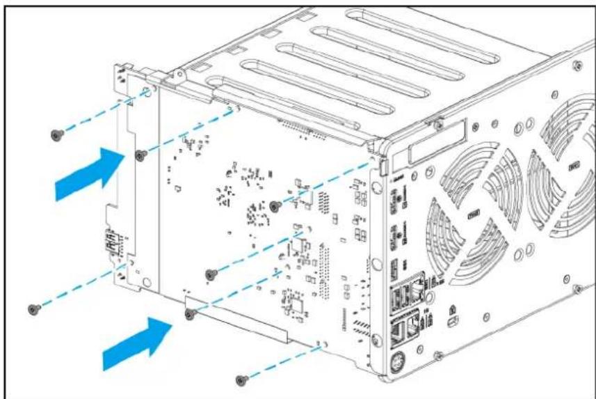
Note
- The pan head M3x5 screws require a Phillips #2 screwdriver.
- A torque of 7 kgf.cm (6.08 lbf.in) ± 0.5 kgf.cm (0.43 lbf.in) is recommended for electric screwdrivers.
- Attach the backplane to the drive cage.
Warning
Do not touch the components on the circuit board or allow the components to come into direct contact with metallic objects. Doing so may cause damage.
a. Carefully insert the connector end of the backplane into the hole at the back of the drive cage.
b. Insert the connector on the backplane into the slot on the system board.

c. Align the holes on the backplane to the screw holes on the drive cage.
d.Attach the screws.

Note
- The pan head M3x5 screws require a Phillips #2 screwdriver.
- A torque of 7 kgf.cm (6.08 lbf.in) ± 0.5 kgf.cm (0.43 lbf.in) is recommended for electric screwdrivers.
- Attach the chassis to the right panel.
a. Insert the chassis into the front of the right panel at an angle of around 20 degrees.
b. Ensure the USB port on the system board is inserted into the USB port hole in the right panel.
c. Place the chassis fully into the right panel.

d. Attach the screws that secure the chassis to the right panel.
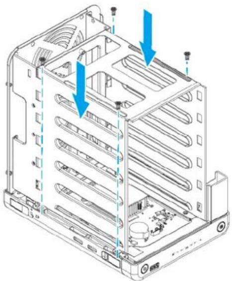
Note
- The flat head self-tapping D3x6 screws require a Phillips #2 screwdriver.
-
A torque of 5 kgf.cm (4.34 lbf.in) ± 0.5 kgf.cm (0.43 lbf.in) is recommended for electric screwdrivers.
-
Install the system fans.
a. Place the NAS in its normal upright position.
b. Align the screw holes on the fans to the screw holes on the rear panel.
Important
To ensure proper cooling, the correct side of the fans must be reattached so that the airflow is directed out of the rear panel. There may be an arrow on the side of the fans that indicates the airflow direction.
c. Attach the screws that secure the fans to the tray.

Note
- The flat head self-tapping M5x10 screws require a Phillips #2 screwdriver.
- A torque of 5 kgf.cm (4.34 lbf.in) ± 0.5 kgf.cm (0.43 lbf.in) is recommended for electric screwdrivers.
d. Connect the fan cable to the backplane.
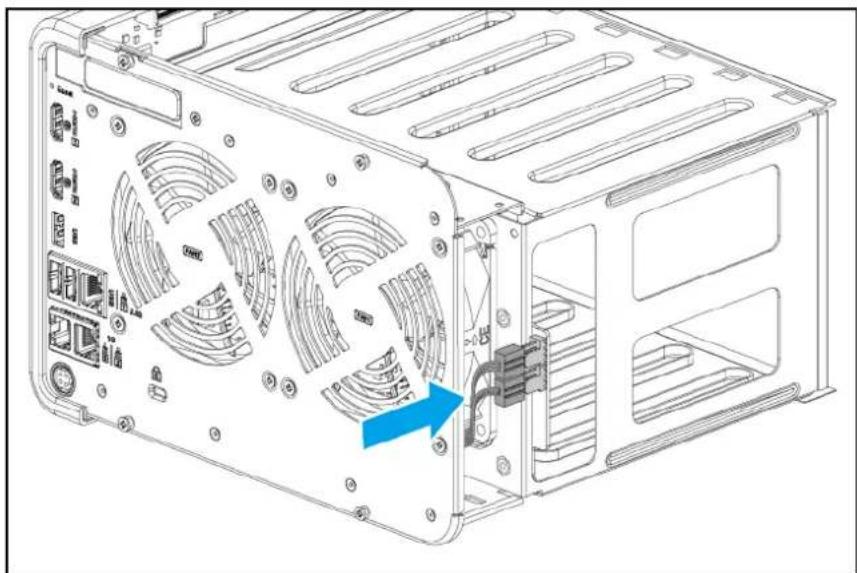
- Attach the case cover.
a. Place the cover on the device.
b.Slide the cover forward.

c. Attach the screws that secure the case cover to the rear panel.
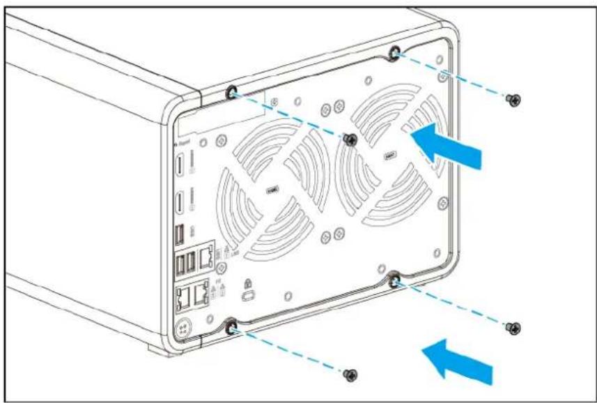
Note
- The pan head M3x5 screws require a Phillips #1 screwdriver.
- A torque of 2.75 kgf.cm (2.39 lbf.in) ± 0.25 kgf.cm (0.22 lbf.in) is recommended for electric screwdrivers.
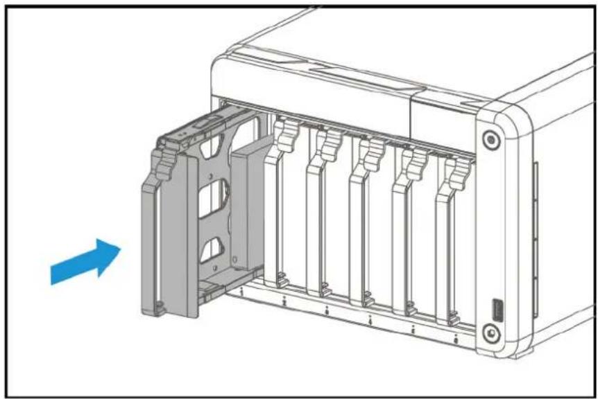
6.Slide each drive tray back into the NAS.
Important
Each drive must be returned to its original bay.
- Attach the front cover.
a. Align the front cover with the grooves on the case and then slide to the right.

b. Slide the lock down to secure the front cover.

TS-AI642 components and screws
Note
The information presented here apply only to the representative model of the NAS category. While all models within a NAS category have the same general structural design, their components and screws may differ in size, quantity, and other specifications.
Important
Recommended torque values are provided for electric screwdrivers. To avoid damage to the screw or component, the actual torque setting should not exceed ± 0.5 kgf.cm (0.43 lbf.in) of the recommended value, unless specified otherwise.
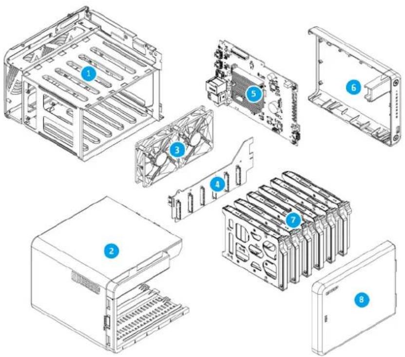
| No. Component (Quantity) | Screw Type (Quantity) | Screwdriver (Torque) | Attached To |
| 1 Chassis (includes drive cage and rear panel) (1) | Flat head Self-tapping D3x6 (4) | Phillips #2 (5 kgf.cm / 4.34 lbf.in) | Right panel |
| 2 Case cover (1) | Flat head M3x5 (4) | Phillips #1 (2.75 kgf.cm / 2.39 lbf.in) | Chassis (Rear panel) |
| 3 System fans (2) | Flat head Self-tapping M5x10 (4 x 2 = 8) | Phillips #2 (5 kgf.cm / 4.34 lbf.in) | Chassis (Rear panel) |
| 4 Backplane (1) | Pan head M3x5 (7) | Phillips #2 (7 kgf.cm / 6.08 lbf.in) | Chassis Drive cage |
| 5 System board (1) | Pan head M3x5 (7) | Phillips #2 (7 kgf.cm / 6.08 lbf.in) | Chassis |
| - HDMI ports on system board (2) | Flat head M2x4 (1 x 2 = 2) | Phillips #1 (2 kgf.cm / 1.74 lbf.in) | Chassis (Rear panel) |
| 6 Right panel (1) | --- | ||
| 7 Drive tray (3.5-inch) (6) | --- | ||
| 2 Front cover (1) | --- |
5. Category C NAS Models
This chapter uses the TVS-h874T as the representative NAS model for category C. The disassembly and reassembly instructions, and the list of components and screws, are based on the representative model.
For details on category C NAS models, see NAS model categorization.
Note
While all NAS models in the same category share the same general structural design, different models may have certain differences in their parts and components in terms of size, quantity, and other specifications. For non-representative models in this category, please use the following topics as a point of reference.
Disassembling the TVS-h874T
Before you start, make sure you read the Repair requirements.
Warning
- Observe electrostatic discharge (ESD) procedures to avoid damage to components.

Moving fan blades: Keep your hands and other body parts away from moving fan blades.

Other moving components: Keep your hands and other body parts away from other moving components.
- Power off the NAS.
- Disconnect the power cord from the electrical outlet.
- Disconnect all cables and external attachments.
- Remove each drive tray.
Important
Remember the number of each drive. Each drive will need to be returned to its original bay.
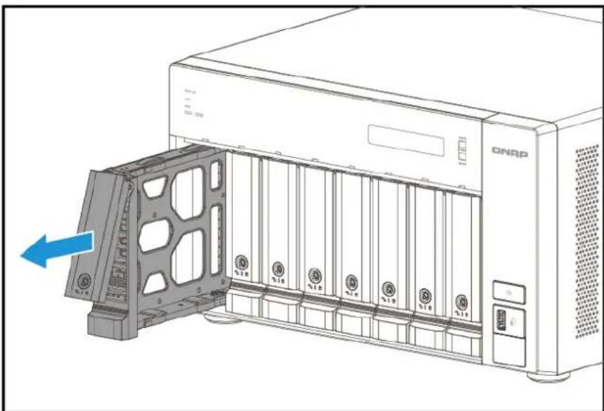
a. Unlock the tray.

b.Pull the tray handle outward.
c.Pull the tray out.
- Remove the case cover.
a. Remove the screws.
Note
- The flat head M3x4 screws require a Phillips #2 screwdriver.
- A torque of 5 kgf.cm (4.34 lbf.in) ± 0.5 kgf.cm (0.43 lbf.in) is recommended for electric screwdrivers.
b.Slide the cover back.
c.Lift the cover off the device.

- Detach the LCD display module cable from the LCD display module.

- Detach the LED circuit board cable from the system board.

- Detach the power supply unit cables.
a. Detach the power cables from both sides of the system board.

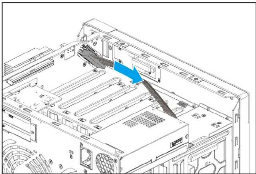
b. Detach the power cable from the backplane.

- Remove the power supply unit.
a. Remove the screws that secure the power supply unit to the chassis and rear panel.

Note
- For detaching from the rear panel, the flat head M3x4 screws require a Phillips #2 screwdriver.
- For detaching from the chassis, the pan head M3x5 screws require a Phillips #2 screwdriver.
- A torque of 5 kgf.cm (4.34 lbf.in) ± 0.5 kgf.cm (0.43 lbf.in) is recommended for electric screwdrivers.
b. Slide the power supply unit forward and then lift it off the chassis.

- Remove existing expansion cards.
a. Remove the screw that secures the expansion card to the chassis.
Note
- The pan head M3x5 screw requires a Phillips #2 screwdriver.
- A torque of 5 kgf.cm (4.34 lbf.in) ± 0.5 kgf.cm (0.43 lbf.in) is recommended for electric screwdrivers.
b.Hold the card by the edges.
c. Carefully pull the card out of the slot.
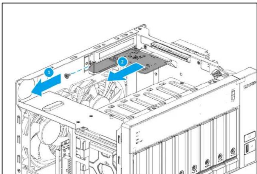
11. Remove the rear panel.
a. Remove the system fan cables from the backplane.

b. Remove the CPU fan cable from the system board.

c. Remove the screws that secure the rear panel to the chassis.

Note
- The flat head M3x4 screws require a Phillips #2 screwdriver.
- A torque of 5 kgf.cm (4.34 lbf.in) ± 0.5 kgf.cm (0.43 lbf.in) is recommended for electric screwdrivers.
- To prevent misalignment or stress on the cover during removal, remove the screws in the following order: top, sides, rear, bottom.
d.Pull the rear panel away from the device.
- Remove the CPU fan and system fans.
a. Remove the screws that secure the fans to the rear panel.

Note
• The self-tapping M5x10 screws require a Phillips #2 screwdriver.
- A torque of 5 kgf.cm (4.34 lbf.in) ± 0.5 kgf.cm (0.43 lbf.in) is recommended for electric screwdrivers.
13. Remove the backplane.
Warning
Do not touch the components on the circuit board or allow the components to come into direct contact with metallic objects. Doing so may cause damage.
a. Remove the screws that secure the backplane to the drive cage.

Note
• The flat head M3x5 screws require a Phillips #2 screwdriver.
- A torque of 7 kgf.cm (6.08 lbf.in) ± 0.5 kgf.cm (0.43 lbf.in) is recommended for electric screwdrivers.
b. Carefully pull the backplane from the drive cage.

- Remove the system board tray from the chassis.
a. Remove the screws that secure the system board tray to the bottom of the chassis.
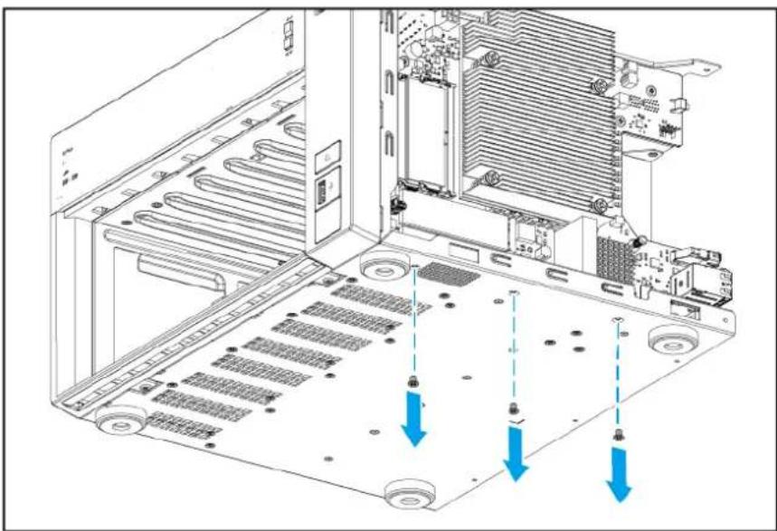
Note
- The flat head M3x4 screws require a Phillips #2 screwdriver.
- A torque of 5 kgf.cm (4.34 lbf.in) ± 0.5 kgf.cm (0.43 lbf.in) is recommended for electric screwdrivers.
b. Place the NAS in its normal upright position.
c. Remove the screws that secure the system board tray to the front of the chassis.

Note
- The flat head M3x4 screws require a Phillips #2 screwdriver.
- A torque of 5 kgf.cm (4.34 lbf.in) ± 0.5 kgf.cm (0.43 lbf.in) is recommended for electric screwdrivers.
d.Slide the system board tray back to remove it from the chassis.

15.Optional: Remove existing M.2 solid-state drives.
a. Unlock the M.2 spacer by pushing down on its edge.

b. Carefully pull the M.2 solid-state drive out of its slot.
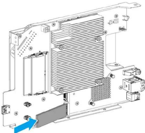
- Remove the system board from the system board tray.
Warning
Do not touch the components on the circuit board or allow the components to come into direct contact with metallic objects. Doing so may cause damage.
a. Remove the screws that secure the system board to the tray.

Note
- The flat head M3x5 screws require a Phillips #2 screwdriver.
- A torque of 7 kgf.cm (6.08 lbf.in) ± 0.5 kgf.cm (0.43 lbf.in) is recommended for electric screwdrivers.
b. Remove the system board.

- Remove the front panel from the chassis.
a. Remove the screws that secure the bottom of the front panel to the bottom of the chassis.
Note
- The flat head M3x5 screws require a Phillips #2 screwdriver.
- A torque of 3 kgf.cm (2.60 lbf.in) ± 0.5 kgf.cm (0.43 lbf.in) is recommended for electric screwdrivers.
b. Release the latches that secure the front panel to the chassis.

Note
You may need to use a tool such as a slotted screwdriver to help push and release the latches.
c.Pull the front panel away at an angle.

- Remove the LED circuit board from the chassis.
Warning
Do not touch the components on the circuit board or allow the components to come into direct contact with metallic objects. Doing so may cause damage.
a. Remove the screws securing the LED circuit board to the chassis.

Note
- The flat head M3x5 screws require a Phillips #2 screwdriver.
- A torque of 7 kgf.cm (6.08 lbf.in) ± 0.5 kgf.cm (0.43 lbf.in) is recommended for electric screwdrivers.
b.Pull the LED circuit board away from the chassis.
- Remove the LCD display module from the chassis.
a. Remove the screws that secure the LCD display module to the chassis.
Note
- The flat head M2.5x4 screws require a Philips #1 screwdriver.
- A torque of 3 kgf.cm (2.60 lbf.in) ± 0.5 kgf.cm (0.43 lbf.in) is recommended for electric screwdrivers.
b. Remove the LCD display module.

- Remove the rubber feet.
a. Remove the screws that secure the rubber feet to the chassis.

Note
- The flat head M3x5 screws require a Philips #2 screwdriver.
- A torque of 5 kgf.cm (4.34 lbf.in) ± 0.5 kgf.cm (0.43 lbf.in) is recommended for electric screwdrivers.
b. Remove the rubber feet.
Reassembling the TVS-h874T
Before you start, make sure you read the Repair requirements.
Warning
- Observe electrostatic discharge (ESD) procedures to avoid damage to components.

Moving fan blades: Keep your hands and other body parts away from moving fan blades.
Other moving components: Keep your hands and other body parts away from other moving components.
- Attach the rubber feet.
a. Align the holes on the rubber feet to the screw holes on the chassis.
b. Attach the screws.

Note
- The flat head M3x5 screws require a Philips #2 screwdriver.
- A torque of 5 kgf.cm (4.34 lbf.in) ± 0.5 kgf.cm (0.43 lbf.in) is recommended for electric screwdrivers.
- Attach the LCD display module to the chassis.
a. Align the holes on the LCD display module to the screw holes on the chassis.
b. Attach the screws.

Note
- The flat head M2.5x4 screws require a Philips #1 screwdriver.
- A torque of 3 kgf.cm (2.60 lbf.in) ± 0.5 kgf.cm (0.43 lbf.in) is recommended for electric screwdrivers.
- Attach the LED circuit board to the chassis.
a. Align the holes on the LED circuit board to the screw holes on the chassis.
b. Attach the screws.
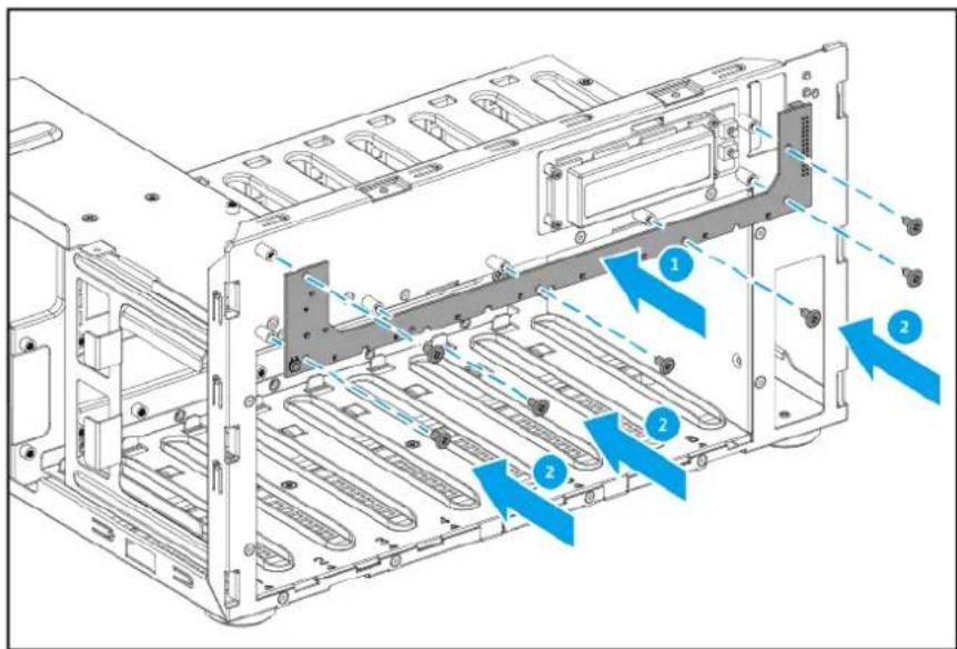
Note
- The flat head M3x5 screws require a Phillips #2 screwdriver.
-
A torque of 7 kgf.cm (6.08 lbf.in) ± 0.5 kgf.cm (0.43 lbf.in) is recommended for electric screwdrivers.
-
Attach the front panel to the chassis.
a. Align the latches on the front panel to the holes on the chassis.
b. Attach the front panel to the chassis.
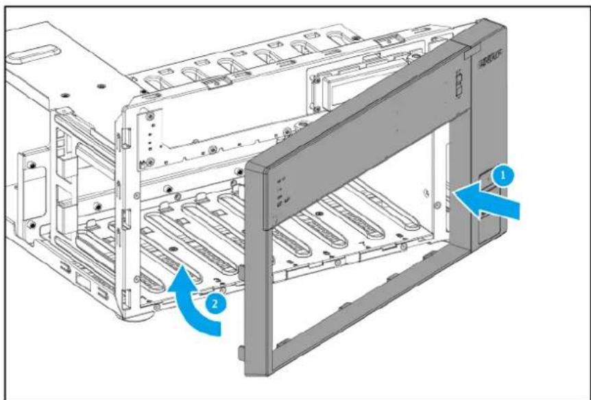
c. Attach the screws that secure the bottom of the front panel to the bottom of the chassis.

Note
- The flat head M3x5 screws require a Phillips #2 screwdriver.
-
A torque of 3 kgf.cm (2.60 lbf.in) ± 0.5 kgf.cm (0.43 lbf.in) is recommended for electric screwdrivers.
-
Attach the system board to the system board tray.
Warning
Do not touch the components on the circuit board or allow the components to come into direct contact with metallic objects. Doing so may cause damage.
a. Align the mounting holes on the system board with the screw holes on the tray.

b. Attach the screws.

Note
- The flat head M3x5 screws require a Phillips #2 screwdriver.
- A torque of 7 kgf.cm (6.08 lbf.in) ± 0.5 kgf.cm (0.43 lbf.in) is recommended for electric screwdrivers.
- Attach the system board tray.
a.Slide the system board tray in.
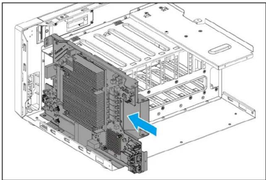
b. Attach the screw that secures the system board tray to the drive cage.

Note
- The flat head M3x4 screws require a Phillips #2 screwdriver.
- A torque of 5 kgf.cm (4.34 lbf.in) ± 0.5 kgf.cm (0.43 lbf.in) is recommended for electric screwdrivers.
c. Attach the screws that secure the system board tray to the front of the chassis.

Note
- The flat head M3x4 screws require a Phillips #2 screwdriver.
- A torque of 5 kgf.cm (4.34 lbf.in) ± 0.5 kgf.cm (0.43 lbf.in) is recommended for electric screwdrivers.
d. Attach the screws that secure the system board tray to the bottom of the chassis.

Note
- The flat head M3x4 screws require a Phillips #2 screwdriver.
-
A torque of 5 kgf.cm (4.34 lbf.in) ± 0.5 kgf.cm (0.43 lbf.in) is recommended for electric screwdrivers.
-
Attach the backplane to the chassis.
Warning
Do not touch the components on the circuit board or allow the components to come into direct contact with metallic objects. Doing so may cause damage.
a. Slide in the backplane until the backplane connector is firmly inserted into the slot on the system board.

b. Attach the screws that secure the backplane to the drive cage.
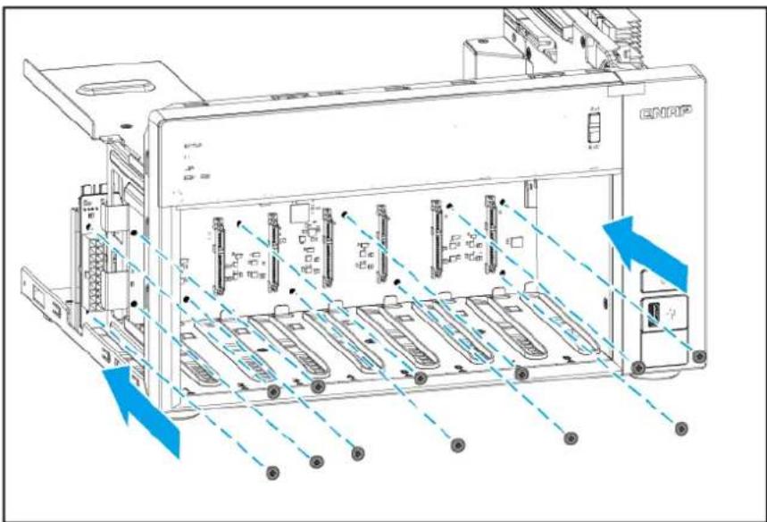
Note
- The flat head M3x5 screws require a Phillips #2 screwdriver.
-
A torque of 7 kgf.cm (6.08 lbf.in) ± 0.5 kgf.cm (0.43 lbf.in) is recommended for electric screwdrivers.
-
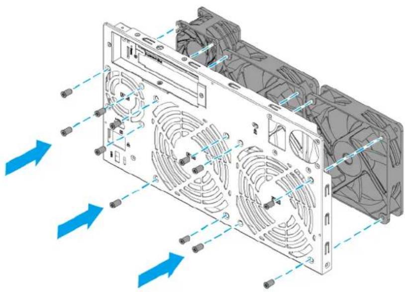
Attach the fans to the rear panel.
a. Align the holes in the fans with the screw holes on the rear panel.
b. Attach the screws.
Note
• The self-tapping M5x10 screws require a Phillips #2 screwdriver.
- A torque of 5 kgf.cm (4.34 lbf.in) ± 0.5 kgf.cm (0.43 lbf.in) is recommended for electric screwdrivers.
9. Attach the rear panel.
a. Align the holes on the rear panel to the screw holes and ports on the chassis.
b. Attach the screws that secure the rear panel to the chassis.

Note
• The flat head M3x4 screws require a Phillips #2 screwdriver.
- A torque of 5 kgf.cm (4.34 lbf.in) ± 0.5 kgf.cm (0.43 lbf.in) is recommended for electric screwdrivers.
- Attach the screws securely in the following order to ensure a proper fit and prevent stress on the cover: bottom, rear, sides, top.
- Attach the fan cables.
a. Attach the system fan cables to the backplane.
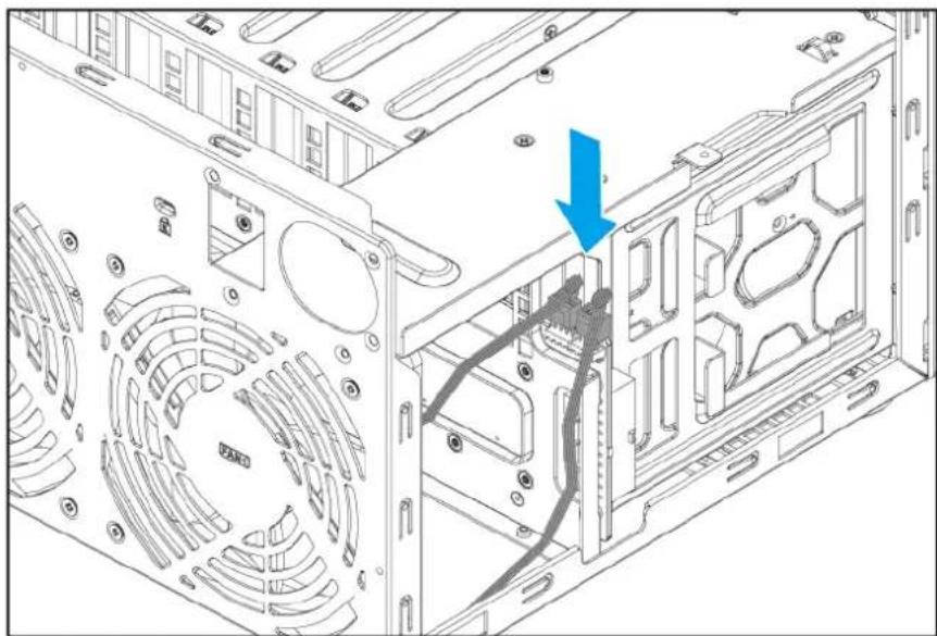
b. Attach the CPU fan cable to the system board.

- Attach the power supply unit.
a. Place the power supply unit on the chassis and slide it back.
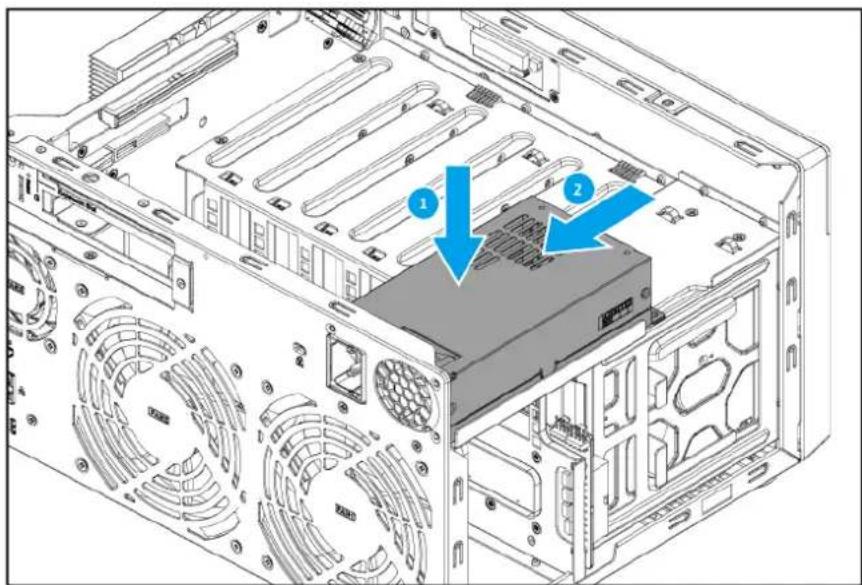
b. Align the screw holes on the power supply unit to the screw holes on the chassis and the rear panel.
c. Attach the screws that secure the power supply unit to the chassis and the rear panel.

Note
- For securing to the rear panel, the flat head M3x4 screws require a Phillips #2 screwdriver.
- For securing to the chassis, the pan head M3x5 screws require a Phillips #2 screwdriver.
-
A torque of 5 kgf.cm (4.34 lbf.in) ± 0.5 kgf.cm (0.43 lbf.in) is recommended for electric screwdrivers.
-
Attach the power supply unit cables.
a. Attach the power supply unit cables to both sides of the system board.


b. Attach the power supply unit cable to the backplane.

- Attach the LED circuit board cable to the system board.

- Attach the LCD display module cable to the LCD display module.

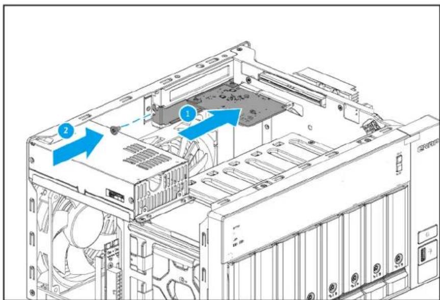
15.Optional: Attach expansion cards.
a. Insert an expansion card into the slot on the system board.
b. Attach the screw that secures the PCIe bracket to the rear panel.
Note
• The pan head M3x5 screw requires a Phillips #2 screwdriver.
- A torque of 5 kgf.cm (4.34 lbf.in) ± 0.5 kgf.cm (0.43 lbf.in) is recommended for electric screwdrivers.
16. Attach the case cover.
a. Place the cover on the device.
b.Slide the cover forward.
c. Attach the screws that secure the case cover to the chassis.

Note
- The flat head M3x4 screws require a Phillips #2 screwdriver.
- A torque of 5 kgf.cm (4.34 lbf.in) ± 0.5 kgf.cm (0.43 lbf.in) is recommended for electric screwdrivers.
17.Load the trays into the bay.
Important
• Each drive must be returned to its original bay.
• After locking the drive trays, ensure the drive tray keys are stored in a safe place.

a. Insert the tray into the bay.
b.Push the handle.

c.Optional: Lock the tray.
TVS-h874T components and screws
Important
The information presented here apply only to the representative model of the NAS category. While all models within a NAS category have the same general structural design, their components and screws may differ in size, quantity, and other specifications.
Note
Recommended torque values are provided for electric screwdrivers. To avoid damage to the screw or component, the actual torque setting should not exceed ± 0.5 kgf.cm (0.43 lbf.in) of the recommended value, unless specified otherwise.

| No. Component(Quantity) | Screw Type(Quantity) | Screwdriver(Torque) | Attached To |
| 1 Case cover(1) | Flat headM3x4(3) | Phillips #2(5 kgf.cm / 4.34 lbf.in) | Chassis |
| 2 Drive tray (3.5-inch)(8) | --- | ||
| 3 Power supply unit(1) | • Flat head M3x4(2)• Pan head M3x5(3) | Phillips #2(5 kgf.cm / 4.34 lbf.in) | • Chassis(2 screws)• Rear panel(3 screws) |
| 4 Front panel(1) | Flat head M3x5(2) | Phillips #2(3 kgf.cm / 2.60 lbf.in) | Chassis |
| 5 LCD display module(1) | Pan head M2.5x4(4) | Phillips #1(3 kgf.cm / 2.60 lbf.in) | Chassis |
| 6 LED circuit board(1) | Pan head M3x5(7) | Phillips #2(7 kgf.cm / 6.08 lbf.in) | Chassis |
| 7 Chassis(1) | --- | ||
| 8 Backplane(1) | Pan head M3x5(12) | Phillips #2(7 kgf.cm / 6.08 lbf.in) | Chassis |
| 9 • CPU fan(1)• System fan(2) | Flat head Self-tapping M5x10(4 x 3 = 12) | Phillips #2(5 kgf.cm / 4.34 lbf.in) | Rear panel |
| 10 Expansion card with bracket (PCIe full height)(Not included with original NAS) | Pan head M3x5(1) | Phillips #2(5 kgf.cm / 4.34 lbf.in) | Chassis |
| 11 PCIe cover(1) | Flat head M3x5(1) | Phillips #2(5 kgf.cm / 4.34 lbf.in) | Chassis |
| 12 Rear panel(1) | Flat head M3x4(9) | Phillips #2(5 kgf.cm / 4.34 lbf.in) | Chassis |
| 13 Drive tray key (2) | --- | ||
| 14 Rubber feet (4) | Pan head M3x5 (4) | Phillips #2 (5 kgf.cm / 4.34 lbf.in) | Chassis |
| 15 System board (1) | Pan head M3x5 (9) | Phillips #2 (7 kgf.cm / 6.08 lbf.in) | System board tray |
| 16 System board tray (1) | Flat head M3x4 (6) | Phillips #2 (5 kgf.cm / 4.34 lbf.in) | Chassis |
Optional Components
These components are not included with the original NAS but may be installed by the user.
| Component (Quantity) | Screw Type (Quantity) | Screwdriver (Torque) | Attached To |
| M.2 SSD(2 maximum, not included with original NAS) | Pan headM2.5x3(2, included with original NAS) | Phillips #2(3 kgf.cm / 2.60 lbf.in) | Inserted into slot on riser card, and then secured to the drive cage with a screw. |
6. Category D NAS Models
WORK IN PROGRESS
This chapter uses the TVS-h1288X as the representative NAS model for category D. The disassembly and reassembly instructions, and the list of components and screws, are based on the representative model.
For details on category D NAS models, see NAS model categorization.
Note
While all NAS models in the same category share the same general structural design, different models may have certain differences in their parts and components in terms of size, quantity, and other specifications. For non-representative models in this category, please use the following topics as a point of reference.
Disassembling the TVS-h1288X
Before you start, make sure you read the Repair requirements.
Warning
- Observe electrostatic discharge (ESD) procedures to avoid damage to components.

Moving fan blades: Keep your hands and other body parts away from moving fan blades.

Other moving components: Keep your hands and other body parts away from other moving components.
- Power off the NAS.
- Disconnect the power cord from the electrical outlet.
- Disconnect all cables and external attachments.
4. Unlock the trays.

2.5-inch drive tray

3.5-inch drive tray
5. Remove all drive trays.
Important
Remember the number of each drive. Each drive will need to be returned to its original bay.
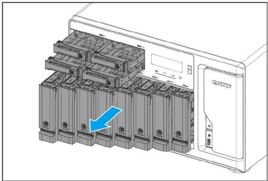
6. Remove the case cover.
a. Remove the screws on the rear panel.
Note
- The flat head M3x4 screws require a Phillips #2 screwdriver.
- A torque of 5 kgf.cm (4.34 lbf.in) ± 0.5 kgf.cm (0.43 lbf.in) is recommended for electric screwdrivers.
b.Slide the cover back.
c.Lift the cover until it is completely detached from the chassis.

7. Remove expansion cards.
Skip this step if you do not have any expansion cards installed on your NAS.
a. Remove the screw that secures the expansion card to the chassis.
Note
- The pan head M3x5 screw requires a Phillips #2 screwdriver.
- A torque of 5 kgf.cm (4.34 lbf.in) ± 0.5 kgf.cm (0.43 lbf.in) is recommended for electric screwdrivers.
b.Hold the card by the edges.
c. Carefully pull the card out of the slot.

Full-height PCIe expansion card

Low-profile PCIe expansion card
8. Remove the CPU fan tray.
a. Detach the CPU fan cables from the system board.

b. Remove the screw that secures the CPU fan tray to the chassis.
Note
- The flat head M3x4 screw requires a Phillips #2 screwdriver.
- A torque of 5 kgf.cm (4.34 lbf.in) ± 0.5 kgf.cm (0.43 lbf.in) is recommended for electric screwdrivers.
c. Press the clip down and then pull the CPU fan tray out of the chassis.

- Remove the air shroud from the CPU fan tray.
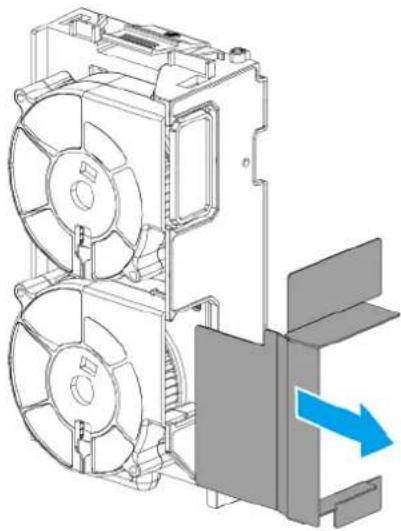
- Remove the CPU fans from CPU the fan tray.
a. Remove the screws that secure the CPU fans to the CPU fan tray.
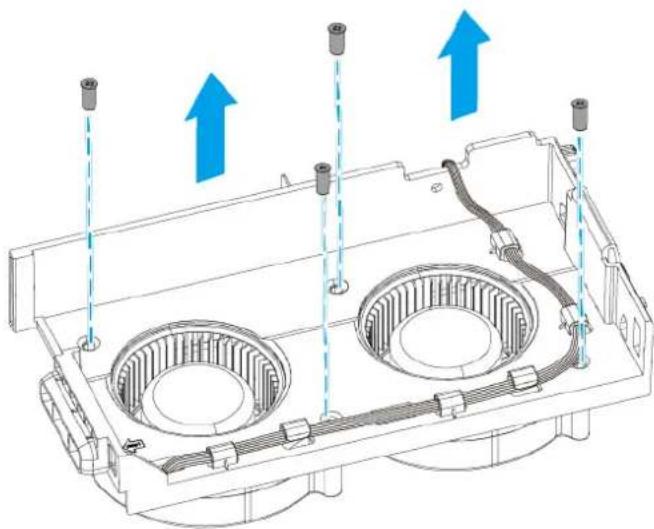
Note
- The flat head M4.5x10 screws require a Phillips #2 screwdriver.
- A torque of 7 kgf.cm (6.08 lbf.in) ± 0.5 kgf.cm (0.43 lbf.in) is recommended for electric screwdrivers.
b. Remove the CPU fan cables from the cable clips on the CPU fan tray.

c. Remove the CPU fans.

11. Remove the rear panel.
a. Detach the system fan cables from the system board.

b. Remove the screws that secure the power supply unit to the rear panel.

Note
- The flat head #6-32x5 screws require a Phillips #2 screwdriver.
- A torque of 5 kgf.cm (4.34 lbf.in) ± 0.5 kgf.cm (0.43 lbf.in) is recommended for electric screwdrivers.
c. Remove the screws that secure the rear panel to the chassis.
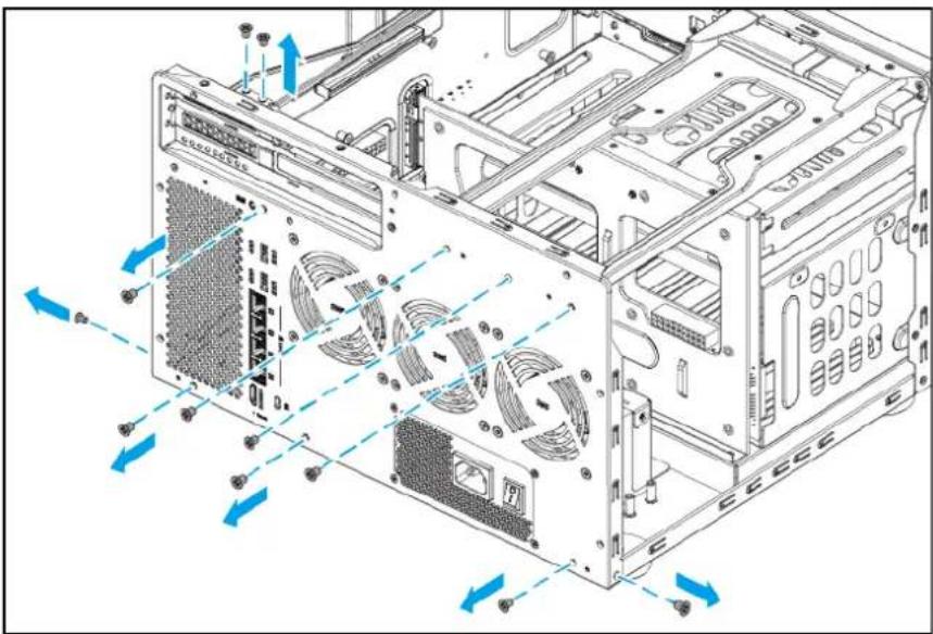
Note
- The flat head M3x4 screws require a Phillips #2 screwdriver.
- A torque of 5 kgf.cm (4.34 lbf.in) ± 0.5 kgf.cm (0.43 lbf.in) is recommended for electric screwdrivers.
d.Remove the rear panel.
- Remove the system fans from the rear panel.
Important
Remember which side of the fans is attached. To ensure proper cooling, the correct side must be reattached so that the airflow is directed out of the rear panel. There may be an arrow on the side of the fans that indicates the airflow direction.
a. Remove the screws that secure the system fans to the rear panel.
Note
- The flat head M5x10 screws require a Phillips #2 screwdriver.
- A torque of 5 kgf.cm (4.34 lbf.in) ± 0.5 kgf.cm (0.43 lbf.in) is recommended for electric screwdrivers.
b. Remove the system fans.

- Remove the top bracket from the chassis.
a. Remove the screws that secure the top bracket to the chassis.
Note
- The flat head M3x4 screws require a Phillips #2 screwdriver.
- A torque of 7 kgf.cm (6.08 lbf.in) ± 0.5 kgf.cm (0.43 lbf.in) is recommended for electric screwdrivers.
b.Slide back the top bracket to remove it from the chassis.

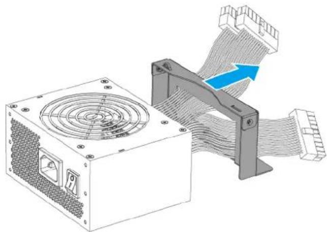
- Remove the power supply unit from the chassis.
a. Detach the power cables from the system board.
b. Detach the power cable from the backplane.

c. Remove the screws that secure the power supply unit bracket to the chassis.
Note
- The flat head M3x4 screws require a Phillips #2 screwdriver.
- A torque of 7 kgf.cm (6.08 lbf.in) ± 0.5 kgf.cm (0.43 lbf.in) is recommended for electric screwdrivers.
d. Remove the power supply unit and power supply unit bracket.

e. Remove the power supply unit bracket from the power supply unit.
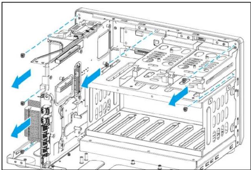
- Remove the front panel from the chassis.
a. Detach the LCD display module cable.
b. Detach the LED cables.

c. Remove the screws that secure the front panel to the chassis.
Note
- The pan head M3x5 screws require a Phillips #2 screwdriver.
- A torque of 5 kgf.cm (4.34 lbf.in) ± 0.5 kgf.cm (0.43 lbf.in) is recommended for electric screwdrivers.
- On other models, there may also be screws that secure the front panel to the bottom of the chassis.
d. Release the latches that secure the front panel to the chassis.

Note
You may need to use a tool such as a slotted screwdriver to help push down and release the latches.
e. Remove the top end of the front panel from the chassis.
f.Pull the front panel away at an angle.
Note
There are hooks at the bottom of the front panel that latch onto the chassis.

- Remove the LED circuit boards from the front panel.
Warning
Do not touch the components on the circuit boards or allow the components to come into direct contact with metallic objects. Doing so may cause damage.
a. Remove the screws that secure the LED circuit boards to the front panel.
Note
• The pan head M3x5 screws require a Phillips #2 screwdriver.
- A torque of 5 kgf.cm (4.34 lbf.in) ± 0.5 kgf.cm (0.43 lbf.in) is recommended for electric screwdrivers.
b. Remove the LED circuit boards.

- Remove the backplane tray from the chassis.
a. Remove the screws that secure the backplane tray to the chassis.
Note
- The flat head M3x4 screws require a Phillips #2 screwdriver.
- A torque of 5 kgf.cm (4.34 lbf.in) ± 0.5 kgf.cm (0.43 lbf.in) is recommended for electric screwdrivers.
b.Slide out the backplane tray.

- Remove the backplane from the backplane tray.
Warning
Do not touch the components on the circuit board or allow the components to come into direct contact with metallic objects. Doing so may cause damage.
a. Remove the screws that secure the backplane to the backplane tray.
Note
- The pan head M3x5 screws require a Phillips #2 screwdriver.
- A torque of 7 kgf.cm (6.08 lbf.in) ± 0.5 kgf.cm (0.43 lbf.in) is recommended for electric screwdrivers.
b. Remove the backplane.

- Remove the system board tray from the chassis.
a.Position the chassis on its left side.
b. Remove the screws that secure the system board tray to the bottom of the chassis.

Note
- The flat head M3x4 screws require a Phillips #2 screwdriver.
- A torque of 5 kgf.cm (4.34 lbf.in) ± 0.5 kgf.cm (0.43 lbf.in) is recommended for electric screwdrivers.
c. Place the chassis in its normal upright position.
d. Remove the screws that secure the system board tray to the front of the chassis.
Note
- The flat head M3x4 screws require a Phillips #2 screwdriver.
- A torque of 5 kgf.cm (4.34 lbf.in) ± 0.5 kgf.cm (0.43 lbf.in) is recommended for electric screwdrivers.
e.Slide out the system board tray.

- Remove the CPU heatsink from the system board.
Warning
Do not touch the components on the circuit board or allow the components to come into direct contact with metallic objects. Doing so may cause damage.
a. Loosen the screws that secure the CPU heatsink to the system board.
Note
- The pan head M3x5 screws require a Phillips #2 screwdriver.
- A torque of 7 kgf.cm (6.08 lbf.in) ± 0.5 kgf.cm (0.43 lbf.in) is recommended for electric screwdrivers.
- First loosen each screw only halfway, and then fully loosen all the screws. If you fully loosen a single screw first, it may become difficult to loosen the other screws.
b. Remove the CPU heatsink.
Tip
There may be a layer of thermal paste preventing the heatsink from easily detaching from the CPU. To break the adhesive tension of the thermal paste, gently twist the heatsink before removing it from the CPU.

- Remove the system board from the system board tray.
Warning
Do not touch the components on the circuit board or allow the components to come into direct contact with metallic objects. Doing so may cause damage.
a. Remove the screws that secure the system board to the tray.

Note
- The pan head M3x5 screws require a Phillips #2 screwdriver.
- A torque of 7 kgf.cm (6.08 lbf.in) ± 0.5 kgf.cm (0.43 lbf.in) is recommended for electric screwdrivers.
b. Remove the system board.
- Remove the LCD display module from the front panel.
a. Remove the screws that secure the LCD display module to the front panel.
Note
- The pan head M2.5x3 screws require a Phillips #1 screwdriver.
- A torque of 3 kgf.cm (2.60 lbf.in) ± 0.5 kgf.cm (0.43 lbf.in) is recommended for electric screwdrivers.
b. Remove the LCD display module.

- Remove the rubber feet from the bottom of the chassis.
a.Position the chassis on its left side.
b. Remove the screws that secure the rubber feet to the chassis.
Note
- The flat head M3x5 screws require a Phillips #2 screwdriver.
- A torque of 5 kgf.cm (4.34 lbf.in) ± 0.5 kgf.cm (0.43 lbf.in) is recommended for electric screwdrivers.
c. Remove the rubber feet.
d. Place the chassis in its normal upright position.
Reassembling the TVS-h1288X
Before you start, make sure you read the Repair requirements.
Warning
- Observe electrostatic discharge (ESD) procedures to avoid damage to components.

Moving fan blades: Keep your hands and other body parts away from moving fan blades.

Other moving components: Keep your hands and other body parts away from other moving components.
- Attach the rubber feet to the bottom of the chassis.
a. Position the chassis on its left side.
b. Align the holes in the rubber feet to the screw holes at the bottom of the chassis.
c. Attach the screws.
Note
- The flat head M3x5 screws require a Phillips #2 screwdriver.
- A torque of 5 kgf.cm (4.34 lbf.in) ± 0.5 kgf.cm (0.43 lbf.in) is recommended for electric screwdrivers.
d. Place the chassis in its normal upright position.
- Attach the LCD display module to the front panel.
a. Align the screw holes in the LCD display module to the screw holes in the front panel.
b. Attach the screws.

Note
- The pan head M2.5x3 screws require a Phillips #1 screwdriver.
- A torque of 3 kgf.cm (2.60 lbf.in) ± 0.5 kgf.cm (0.43 lbf.in) is recommended for electric screwdrivers.
c. Place the chassis in its normal upright position.
- Attach the system board to the system board tray.
Warning
Do not touch the components on the circuit board or allow the components to come into direct contact with metallic objects. Doing so may cause damage.
a. Align the mounting holes in the system board with the screw holes on the tray.
b. Attach the screws.

Note
- The pan head M3x5 screws require a Phillips #2 screwdriver.
-
A torque of 7 kgf.cm (6.08 lbf.in) ± 0.5 kgf.cm (0.43 lbf.in) is recommended for electric screwdrivers.
-
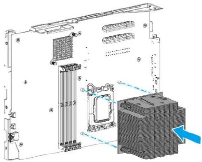
Attach the CPU heatsink to the system board.
Warning
Do not touch the components on the circuit board or allow the components to come into direct contact with metallic objects. Doing so may cause damage.
a. Align the screws on the heatsink with the screw holes on the system board.
Important
• To ensure proper cooling of the CPU, make sure the heatsink fins are parallel to the fan's airflow direction so that the air flows through all fins.
- The thermal paste on the CPU must be evenly distributed so that the entire bottom surface of the heatsink is in contact with the thermal paste. You may need to reapply the thermal paste if it did not break off cleanly when you detached the heatsink from the CPU.
b.Tighten the screws.
Note
- The pan head M3x5 screws require a Phillips #2 screwdriver.
- A torque of 5 kgf.cm (4.34 lbf.in) ± 0.5 kgf.cm (0.43 lbf.in) is recommended for electric screwdrivers.
- First tighten each screw only halfway to stabilize the heatsink in place, and then fully tighten all the screws. If you fully attach a single screw first, you will not be able to attach the other screws.
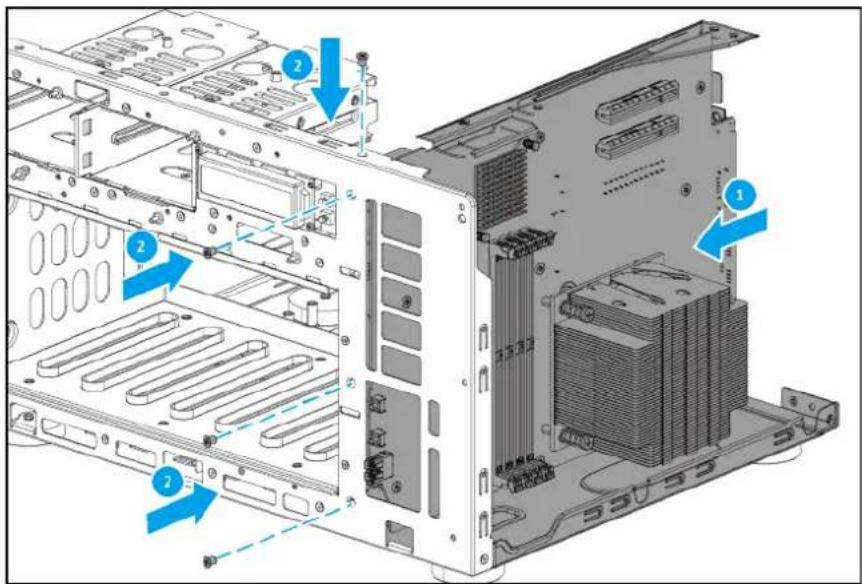
- Attach the system board tray to the chassis.
a.Slide the system board tray into the chassis.
b. Attach the screws that secure the tray to the front of the chassis.
Note
- The flat head M3x4 screws require a Phillips #2 screwdriver.
- A torque of 5 kgf.cm (4.34 lbf.in) ± 0.5 kgf.cm (0.43 lbf.in) is recommended for electric screwdrivers.
c.Position the chassis on its left side.
d. Attach the screws that secure the tray to the bottom of the chassis.

Note
- The flat head M3x4 screws require a Phillips #2 screwdriver.
- A torque of 5 kgf.cm (4.34 lbf.in) ± 0.5 kgf.cm (0.43 lbf.in) is recommended for electric screwdrivers.
e. Place the chassis in its normal upright position.
- Attach the backplane to the backplane tray.
Warning
Do not touch the components on the circuit board or allow the components to come into direct contact with metallic objects. Doing so may cause damage.
a. Align the mounting holes in the backplane to the screw holes on the backplane tray.
b. Attach the screws.
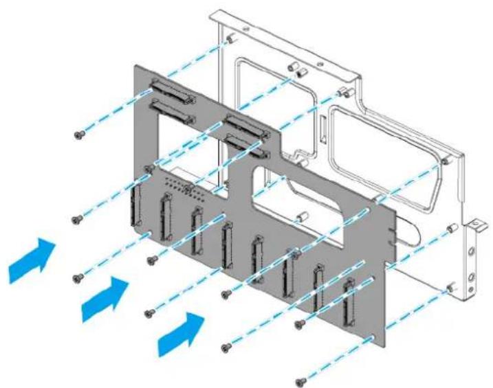
Note
- The pan head M3x5 screws require a Phillips #2 screwdriver.
- A torque of 7 kgf.cm (6.08 lbf.in) ± 0.5 kgf.cm (0.43 lbf.in) is recommended for electric screwdrivers.
- Attach the backplane tray to the chassis.
a. Slide in the backplane tray until the backplane connector is firmly inserted into the slot on the system board.
b. Attach the screws that secure the backplane tray to the chassis.

Note
- The flat head M3x4 screws require a Phillips #2 screwdriver.
-
A torque of 5 kgf.cm (4.34 lbf.in) ± 0.5 kgf.cm (0.43 lbf.in) is recommended for electric screwdrivers.
-
Attach the LED circuit boards to the front panel.
Warning
Do not touch the components on the circuit boards or allow the components to come into direct contact with metallic objects. Doing so may cause damage.
a. Align the mounting holes in the LED circuit boards to the screw holes on the front panel.
b. Attach the screws that secure the LED circuit boards to the front panel.
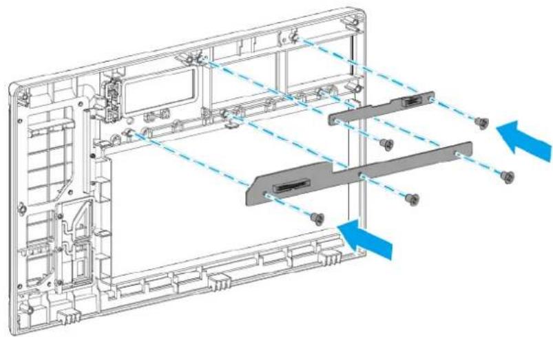
Note
- The pan head M3x5 screws require a Phillips #2 screwdriver.
-
A torque of 5 kgf.cm (4.34 lbf.in) ± 0.5 kgf.cm (0.43 lbf.in) is recommended for electric screwdrivers.
-
Attach the front panel to the chassis.
a. Insert the hooks at the bottom of the front panel into the holes on the chassis.
b. Attach the top of the front panel to the chassis.

c.Ensure the latches on the front panel are secured to the chassis.

d. Attach the screws that secure the front panel to the chassis.
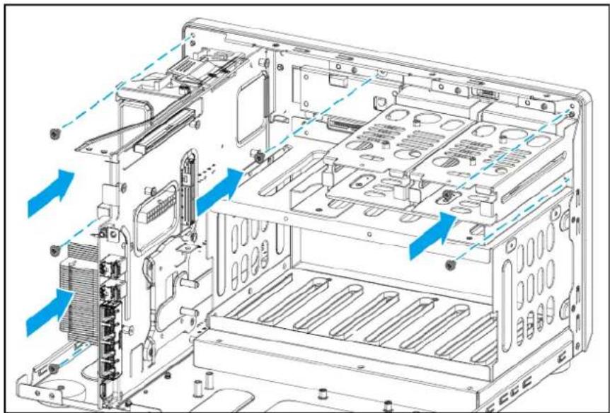
Note
- The pan head M3x5 screws require a Phillips #2 screwdriver.
- A torque of 5 kgf.cm (4.34 lbf.in) ± 0.5 kgf.cm (0.43 lbf.in) is recommended for electric screwdrivers.
- On other models, there may also be screws that secure the front panel to the bottom of the chassis.
e.Attach the LCD display module cable to the LCD display module.
f.Attach the LED cables to the LED circuit boards.

- Attach the power supply unit.
a. Attach the power supply unit bracket to the power supply unit.

b. Insert the power supply unit and power supply unit bracket into the chassis.
c. Align the screw holes in the power supply unit bracket with the screw holes on the chassis.
d.Attach the screws.

Note
- The flat head M3x4 screws require a Phillips #2 screwdriver.
- A torque of 7 kgf.cm (6.08 lbf.in) ± 0.5 kgf.cm (0.43 lbf.in) is recommended for electric screwdrivers.
e.Attach the power cables to the system board.
f.Attach the power cable to the backplane.
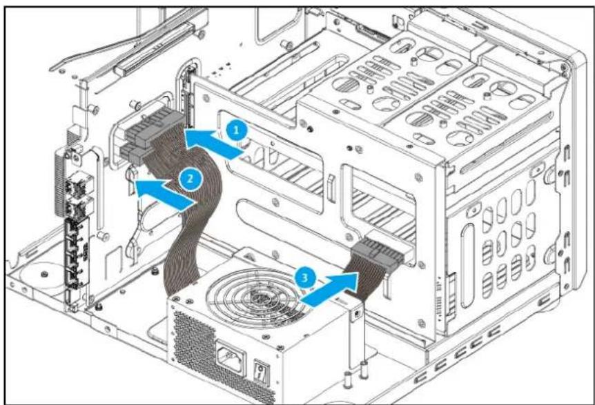
- Attach the top bracket to the chassis.
a.Slide in the top bracket.
b. Align the screw holes in the top bracket to the screw holes on the chassis.
c.Attach the screws.

Note
- The flat head M3x4 screws require a Phillips #2 screwdriver.
- A torque of 7 kgf.cm (6.08 lbf.in) ± 0.5 kgf.cm (0.43 lbf.in) is recommended for electric screwdrivers.
- Attach the system fans to the rear panel.
Important
To ensure proper cooling, the correct side of the fans must be reattached so that the airflow is directed out of the rear panel. There may be an arrow on the side of the fans that indicates the airflow direction.
a. Align the screw holes in the fans with the screw holes on the rear panel.
b. Attach the screws.
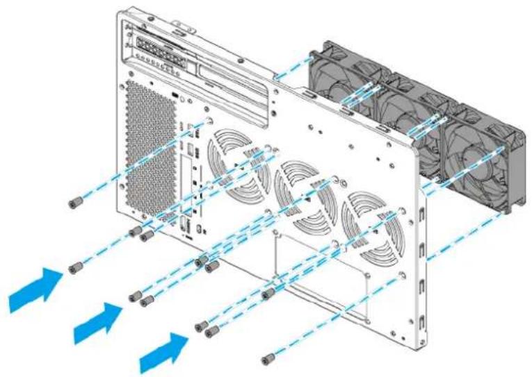
Note
- The flat head M5x10 screws require a Phillips #2 screwdriver.
-
A torque of 5 kgf.cm (4.34 lbf.in) ± 0.5 kgf.cm (0.43 lbf.in) is recommended for electric screwdrivers.
-
Attach the rear panel to the chassis.
a. Align the screw holes on the rear panel to the screw holes and ports on the chassis.
b. Attach the screws that secure the rear panel to the chassis.

Note
- The flat head M3x4 screws require a Phillips #2 screwdriver.
- A torque of 5 kgf.cm (4.34 lbf.in) ± 0.5 kgf.cm (0.43 lbf.in) is recommended for electric screwdrivers.
c. Attach the screws that secure the power supply unit to the rear panel.

Note
- The flat head #6-32x5 screws require a Phillips #2 screwdriver.
- A torque of 5 kgf.cm (4.34 lbf.in) ± 0.5 kgf.cm (0.43 lbf.in) is recommended for electric screwdrivers.
d. Attach the system fan cables to the system board.

- Attach the CPU fans to the CPU fan tray.
a.Pass the CPU fan cables through the holes in the CPU fan tray.
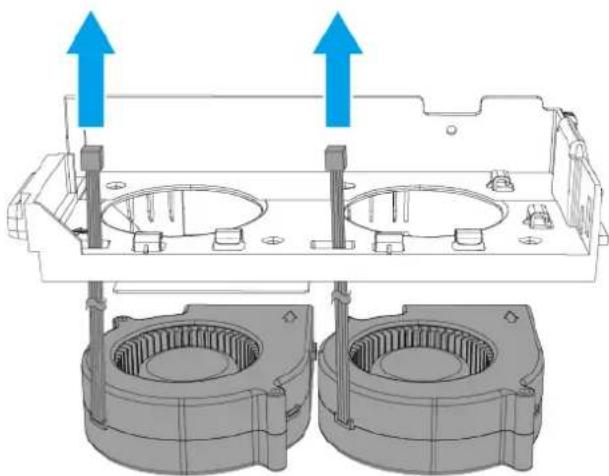
b. Align the screw holes on the CPU fans to the screw holes in the CPU fan tray.
c. Attach the screws that secure the CPU fans to the CPU fan tray.

Note
- The flat head M4.5x10 screws require a Phillips #2 screwdriver.
- A torque of 7 kgf.cm (6.08 lbf.in) ± 0.5 kgf.cm (0.43 lbf.in) is recommended for electric screwdrivers.
d. Attach the CPU fan cables to the cable clips on the CPU fan tray.

- Attach the air shroud to the CPU fan tray.
The air shroud has three adhesive surfaces: Two attach to the CPU fan tray and one attaches to the lower CPU fan.

- Attach the CPU fan tray to the chassis.
a. Insert the bottom of the CPU fan tray into the chassis.
b.Push the CPU fan tray toward the system board until the latch locks the CPU fan tray in place.
c. Attach the screw that secures the CPU fan tray to the chassis.

Note
• The flat head M3x4 screw requires a Phillips #2 screwdriver.
- A torque of 5 kgf.cm (4.34 lbf.in) ± 0.5 kgf.cm (0.43 lbf.in) is recommended for electric screwdrivers.
d. Attach the fan cables to the system board.

17.Optional: Attach expansion cards.
a. Insert an expansion card into the slot on the system board.
b. Attach the screw that secures the PCIe bracket to the rear panel.

Full-height PCIe expansion card

Low-profile PCIe expansion card
Note
- The pan head M3x5 screw requires a Phillips #2 screwdriver.
-
A torque of 5 kgf.cm (4.34 lbf.in) ± 0.5 kgf.cm (0.43 lbf.in) is recommended for electric screwdrivers.
-
Attach the case cover.
a. Place the case cover on the device.
b.Slide the case cover forward.
c. Attach the screws that secure the case cover to the chassis.

Note
- The flat head M3x4 screws require a Phillips #2 screwdriver.
- A torque of 5 kgf.cm (4.34 lbf.in) ± 0.5 kgf.cm (0.43 lbf.in) is recommended for electric screwdrivers.
19.Slide each drive tray back into the NAS.
Important
Each drive must be returned to its original bay.

- Optional: Lock the drive trays.
Important
After locking the drive trays, ensure the drive tray keys are stored in a safe place.

2.5-inch trays

3.5-inch trays
TVS-h1288X components and screws
Note
The information presented here apply only to the representative model of the NAS category. While all models within a NAS category have the same general structural design, their components and screws may differ in size, quantity, and other specifications.
Important
Recommended torque values are provided for electric screwdrivers. To avoid damage to the screw or component, the actual torque setting should not exceed ± 0.5 kgf.cm (0.43 lbf.in) of the recommended value, unless specified otherwise.
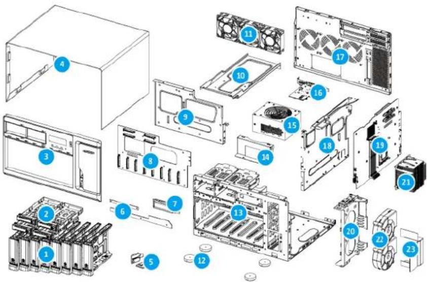
| No. Component (Quantity) | Screw Type (Quantity) | Screwdriver (Torque) | Attached To |
| 1 Drive tray (3.5-inch) (8) | --- | ||
| 2 Drive tray (2.5-inch) (4) | --- | ||
| 3 Front panel (1) | Pan head M3x5 (6) | Phillips #2 (5 kgf.cm / 4.34 lbf.in) | Chassis |
| 4 Case cover (1) | Flat head M3x4 (7) | Phillips #2 (5 kgf.cm / 4.34 lbf.in) | Rear panel |
| No. | Component (Quantity) | Screw Type (Quantity) | Screwdriver (Torque) | Attached To |
| 5 | Drive tray key (2) | --- | ||
| 6 | LED circuit board (2) | Pan head M3x5 (2 + 3 = 5) | Phillips #2 (5 kgf.cm / 4.34 lbf.in) | Front panel |
| 7 | LCD display module (1) | Pan head M2.5x3 (2) | Phillips #1 (3 kgf.cm / 2.60 lbf.in) | Chassis |
| 8 | Backplane (1) | Pan head M3x5 (12) | Phillips #2 (7 kgf.cm / 6.08 lbf.in) | Backplane tray |
| 9 | Backplane tray (1) | Flat head M3x4 (6) | Phillips #2 (5 kgf.cm / 4.34 lbf.in) | Chassis |
| 10 | Top bracket (1) | Flat head M3x4 (6) | Phillips #2 (7 kgf.cm / 6.08 lbf.in) | Chassis |
| 11 | System fan (3) | Flat head M5x10 (4 x 3 = 12) | Phillips #2 (5 kgf.cm / 4.34 lbf.in) | Rear panel |
| 12 | Rubber feet (4) | Pan head M5x10 (1 x 4 = 4) | Phillips #2 (5 kgf.cm / 4.34 lbf.in) | Chassis |
| 13 | Chassis (1) | --- | ||
| 14 | Power supply unit bracket (1) | Flat head M3x4 (2) | Phillips #2 (7 kgf.cm / 6.08 lbf.in) | Chassis |
| 15 | Power supply unit (1) | Flat head #6-32x5 (4) | Phillips #2 (5 kgf.cm / 4.34 lbf.in) | Rear panel |
| 16 | Expansion card with bracket (PCIe full height) (1) | Pan head M3x5 (1) | Phillips #2 (5 kgf.cm / 4.34 lbf.in) | Rear panel |
| No. Component (Quantity) | Screw Type (Quantity) | Screwdriver (Torque) | Attached To |
| 17 Rear panel (1) | Flat head M3x4 (11) | Phillips #2 (5 kgf.cm / 4.34 lbf.in) | • Chassis (5 screws) • Top bracket (3 screws) • System board tray (3 screws) |
| 18 System board tray (1) | Flat head M3x4 (8) | Phillips #2 (5 kgf.cm / 4.34 lbf.in) | Chassis |
| 19 System board (1) | Pan head M3x5 (11) | Phillips #2 (7 kgf.cm / 6.08 lbf.in) | System board tray |
| 20 Fan tray (1) | Flat head M3x4 (1) | Phillips #2 (5 kgf.cm / 4.34 lbf.in) | System board tray |
| 21 CPU heatsink (1) | Pan head M3x5 (4) | Phillips #2 (5 kgf.cm / 4.34 lbf.in) | System board |
| 22 CPU fan (2) | Flat head M4.5x10 (2 x 2 = 4) | Phillips #2 (7 kgf.cm / 6.08 lbf.in) | Fan tray |
| 23 Air shroud (1) | -- The air shroud has | adhesive surfaces that attach to the fan tray and the lower CPU fan. | |
Optional Components
These components are not included with the original NAS but may be installed by the user.
| Component(Quantity) | Screw Type(Quantity) | Screwdriver(Torque) | Attached To |
| Expansion card with bracket (PCIe low profile)(Not included with original NAS) | Pan headM3x5(1) | Phillips #2(5 kgf.cm / 4.34 lbf.in) | Rear panel |
7. Category E NAS Models
This chapter uses the TS-h1677AXU-RP as the representative NAS model for category E. The disassembly and reassembly instructions, and the list of components and screws, are based on the representative model.
For details on category E NAS models, see NAS model categorization.
Note
While all NAS models in the same category share the same general structural design, different models may have certain differences in their parts and components in terms of size, quantity, and other specifications. For non-representative models in this category, please use the following topics as a point of reference.
Disassembling the TS-h1677AXU-RP
Before you start, make sure you read the Repair requirements.
Warning
- Observe electrostatic discharge (ESD) procedures to avoid damage to components.

Moving fan blades: Keep your hands and other body parts away from moving fan blades.

Other moving components: Keep your hands and other body parts away from other moving components.
- To avoid potential injury or damage to components, ensure that the drives and other internal system components have cooled before touching them.
- Power off the NAS.
- Disconnect the power cord from the electrical outlet.
-
Disconnect all cables and external attachments.
-
Remove all drive trays.
Important
Remember the number of each drive. Each drive will need to be returned to its original bay.
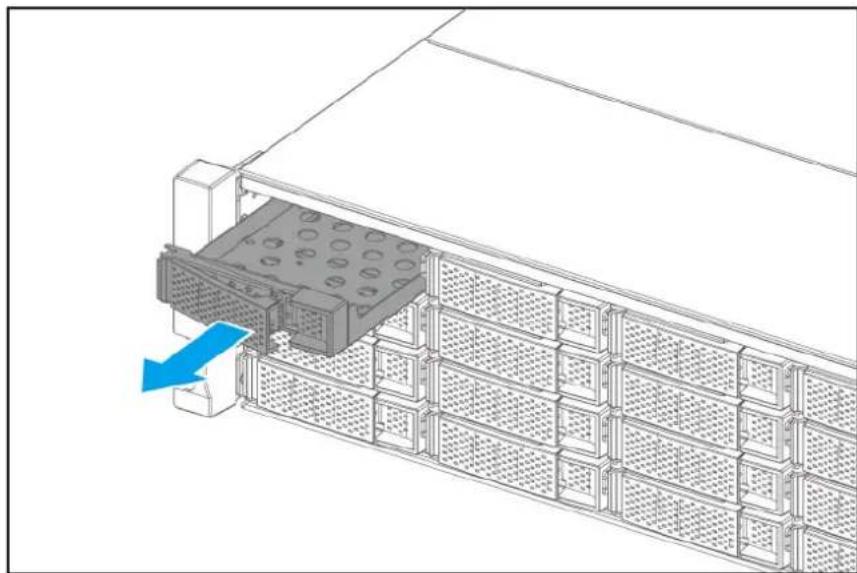
- Remove the rear top cover.
a. Loosen the screws that secure the top cover to the chassis.

b.Slide the rear top cover back.
c.Lift the rear top cover off the device.

- Remove the front top cover.
a. Remove the screws that secure the front top cover to the chassis.
Note
- The flat head M3x4 screws require a Phillips #2 screwdriver.
- A torque of 5 kgf.cm (4.34 lbf.in) ± 0.5 kgf.cm (0.43 lbf.in) is recommended for electric screwdrivers.
b.Slide the front top cover backward.
c.Lift the front top cover off the device.

7.Remove the CPU fan duct.
Note
Skip this step if your device does not have a CPU fan duct.
a. Detach the bottom hooks of the CPU fan duct from the CPU heatsink screws.

b.Tilt the CPU fan duct.
c.Pull the CPU fan duct out of the device.

- Remove the fan tray from the chassis.
a.Disconnect the power connectors of all fans from the system board.
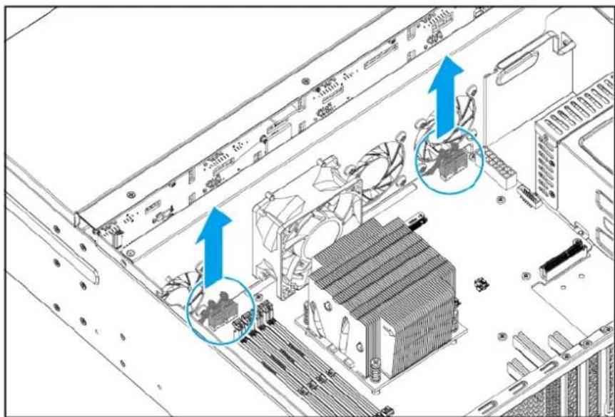
b. Remove the screws that secure the fan tray to the chassis.
Note
- The flat head M3x4 screws require a Phillips #2 screwdriver.
- A torque of 5 kgf.cm (4.34 lbf.in) ± 0.5 kgf.cm (0.43 lbf.in) is recommended for electric screwdrivers.
c.Lift the fan tray out of the chassis.

- Remove the fans from the fan tray.
a. Remove the screws that secure the fans to the fan tray.
Note
- The self-tapping D5x10 screws require a Phillips #2 screwdriver.
- A torque of 5 kgf.cm (4.34 lbf.in) ± 0.5 kgf.cm (0.43 lbf.in) is recommended for electric screwdrivers.
b. Remove the fans.
Important
Remember which side of the fan is attached. To ensure proper cooling, the correct side must be reattached so that the airflow is directed out of the rear panel. There may be an arrow on the side of the fan that indicates the airflow direction.

- Remove the power supply units
a.Firmly press the PSU latch toward the PSU handle.
b.Pull the PSU out.

- Remove the power supply cage.
a. Place the NAS upside down.
b. Remove the screws that secure the power supply cage to the bottom of the chassis.

Note
• The flat head M3x4 screws require a Phillips #2 screwdriver.
- A torque of 5 kgf.cm (4.34 lbf.in) ± 0.5 kgf.cm (0.43 lbf.in) is recommended for electric screwdrivers.
c. Place the NAS in its normal upright position.
d.Disconnect the PSU cables from the backplane and system board.

e. Remove the screws that secure the power supply cage to the rear panel.
Note
- The flat head M3x4 screws require a Phillips #2 screwdriver.
- A torque of 5 kgf.cm (4.34 lbf.in) ± 0.5 kgf.cm (0.43 lbf.in) is recommended for electric screwdrivers.
f.Pull the power supply cage out.
- Remove existing PCIe expansion cards.
a. Remove the screw that secures the expansion card to the rear panel.
Note
- The flat head M3x5 screw requires a Phillips #2 screwdriver.
- A torque of 5 kgf.cm (4.34 lbf.in) ± 0.5 kgf.cm (0.43 lbf.in) is recommended for electric screwdrivers.
b.Pull the expansion card away from the slot.
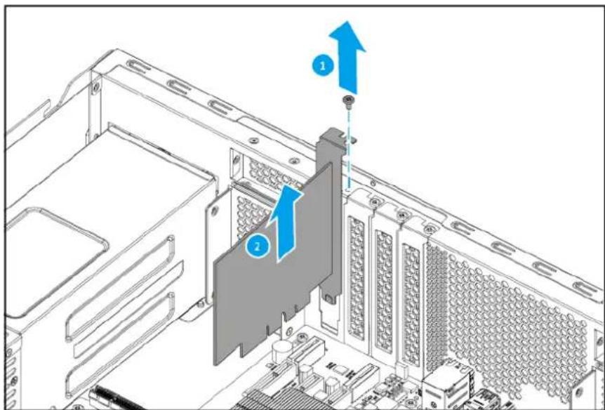
- Remove the rear panel.
a. Remove the screws that secure the rear panel to the chassis.
Note
- The flat head M3x4 screws require a Phillips #2 screwdriver.
- A torque of 5 kgf.cm (4.34 lbf.in) ± 0.5 kgf.cm (0.43 lbf.in) is recommended for electric screwdrivers.
b.Pull the rear panel away from the chassis.

14. Remove the system board.
Warning
Do not touch the components on the circuit board or allow the components to come into direct contact with metallic objects. Doing so may cause damage.
a. Remove the screws that secure the system board to the chassis.
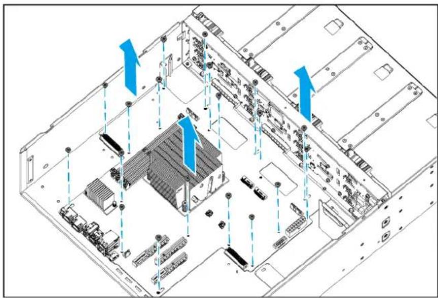
Note
- The pan head M3x5 screws require a Phillips #2 screwdriver.
- A torque of 7 kgf.cm (6.08 lbf.in) ± 0.5 kgf.cm (0.43 lbf.in) is recommended for electric screwdrivers.
b.Slide the system board backward.
c.Lift the system board off the chassis.

- Remove the backplane tray.
a. Place the NAS upside down.
b.Remove the screws that secure the backplane tray to the bottom of the chassis.
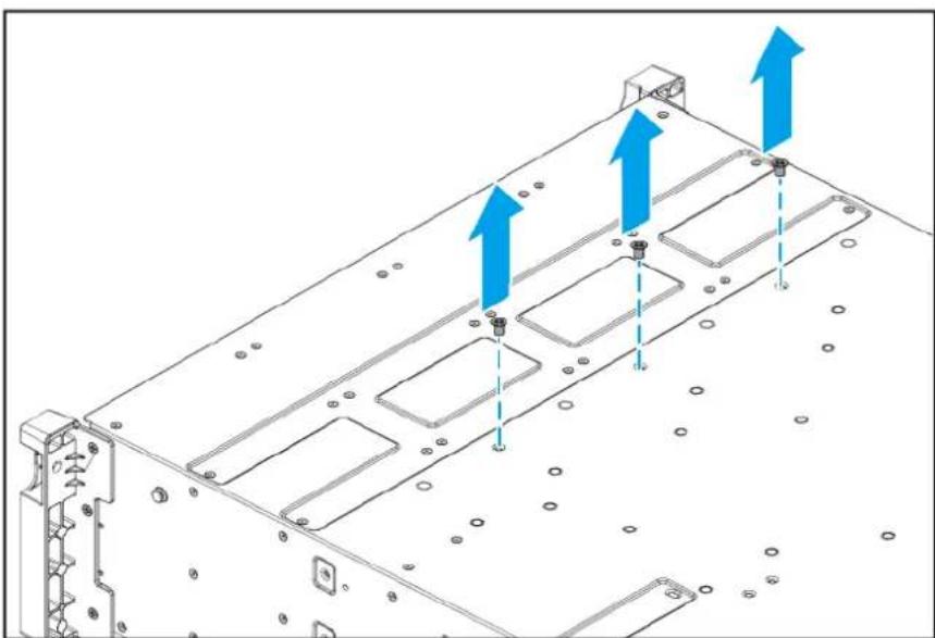
Note
- The flat head M3x4 screws require a Phillips #2 screwdriver.
- A torque of 5 kgf.cm (4.34 lbf.in) ± 0.5 kgf.cm (0.43 lbf.in) is recommended for electric screwdrivers.
c. Place the NAS in its normal upright position.
d. Remove the screws that secure the backplane tray to the sides of the chassis.

Note
- The flat head M3x4 screws require a Phillips #2 screwdriver.
- A torque of 5 kgf.cm (4.34 lbf.in) ± 0.5 kgf.cm (0.43 lbf.in) is recommended for electric screwdrivers.
e.Disconnect the LED cable from the backplane.
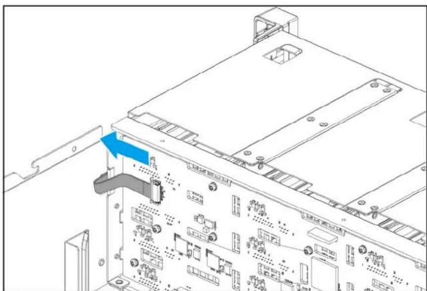
f.Lift the backplane tray out of the chassis.

- Remove the backplane from the backplane tray.
Warning
Do not touch the components on the circuit board or allow the components to come into direct contact with metallic objects. Doing so may cause damage.
a. Remove the screws that secure the backplane to the backplane tray.
Note
- The flat head M3x5 screws require a Phillips #2 screwdriver.
- A torque of 7 kgf.cm (6.08 lbf.in) ± 0.5 kgf.cm (0.43 lbf.in) is recommended for electric screwdrivers.
b. Pull the backplane away from the backplane tray.
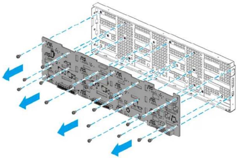
- Remove the handles.
a. Remove the screws that secure the right handle to the chassis.
Note
- The flat head M3x5 screws require a Phillips #2 screwdriver.
- A torque of 7 kgf.cm (6.08 lbf.in) ± 0.5 kgf.cm (0.43 lbf.in) is recommended for electric screwdrivers.
b. Pull the right handle and LED cable out of the chassis.
c. Remove the screws that secure the left handle to the chassis.
d. Pull the left handle off the chassis.
Reassembling the TS-h1677AXU-RP
Before you start, make sure you read the Repair requirements.
Warning
- Observe electrostatic discharge (ESD) procedures to avoid damage to components.
Moving fan blades: Keep your hands and other body parts away from moving fan blades.

Other moving components: Keep your hands and other body parts away from other moving components.
- Optional: Install the handles.
a. Insert the LED cable into the chassis.
b. Align the holes on the right handle with the holes on the chassis.
c. Attach the screws that secure the right handle to the chassis.
Note
- The flat head M3x5 screws require a Phillips #2 screwdriver.
- A torque of 7 kgf.cm (6.08 lbf.in) ± 0.5 kgf.cm (0.43 lbf.in) is recommended for electric screwdrivers.
d. Align the holes on the left handle with the holes on the chassis.
e. Attach the screws that secure the left handle to the chassis.
Note
- The flat head M3x5 screws require a Phillips #2 screwdriver.
-
A torque of 7 kgf.cm (6.08 lbf.in) ± 0.5 kgf.cm (0.43 lbf.in) is recommended for electric screwdrivers.
-
Attach the backplane to the backplane tray.
Warning
Do not touch the components on the circuit board or allow the components to come into direct contact with metallic objects. Doing so may cause damage.
a. Align the holes in the backplane with the screw holes on the backplane tray.
b. Attach the screws that secure the backplane to the backplane tray.

Note
- The flat head M3x5 screws require a Phillips #2 screwdriver.
- A torque of 7 kgf.cm (6.08 lbf.in) ± 0.5 kgf.cm (0.43 lbf.in) is recommended for electric screwdrivers.
3. Install the backplane tray.
a. Insert the backplane tray into the chassis.

b. Place the NAS upside down.
c. Attach the screws that secure the backplane tray to the bottom of the chassis.

Note
- The flat head M3x4 screws require a Phillips #2 screwdriver.
- A torque of 5 kgf.cm (4.34 lbf.in) ± 0.5 kgf.cm (0.43 lbf.in) is recommended for electric screwdrivers.
d. Place the NAS in its normal upright position.
e.Attach the screws that secure the backplane tray to the sides of the chassis.

Note
• The flat head M3x4 screws require a Phillips #2 screwdriver.
- A torque of 5 kgf.cm (4.34 lbf.in) ± 0.5 kgf.cm (0.43 lbf.in) is recommended for electric screwdrivers.
f. Connect the LED cable to the backplane.

- Install the system board.
Warning
Do not touch the components on the circuit board or allow the components to come into direct contact with metallic objects. Doing so may cause damage.
a. Align the positioning holes on the system board with the positioning posts on the chassis.
Note
The positioning posts also serve as screw holes for mounting the system board.
b. Place the system board on the chassis.
c.Slide the system board forward.
d. Make sure the connectors on the system board are firmly inserted into the slots on the backplane.
e.Attach the screws that secure the system board to the chassis.

Note
- The pan head M3x5 screws require a Phillips #2 screwdriver.
-
A torque of 7 kgf.cm (6.08 lbf.in) ± 0.5 kgf.cm (0.43 lbf.in) is recommended for electric screwdrivers.
-
Install the rear panel.
a. Attach the rear panel to the chassis.
b. Attach the screws that secure the rear panel to the chassis.

Note
- The flat head M3x4 screws require a Phillips #2 screwdriver.
-
A torque of 5 kgf.cm (4.34 lbf.in) ± 0.5 kgf.cm (0.43 lbf.in) is recommended for electric screwdrivers.
-
Install the power supply cage.
a. Insert the power supply cage through the rear panel into the chassis.
b. Attach the screws that secure the power supply cage to the rear panel.
Note
- The flat head M3x4 screws require a Phillips #2 screwdriver.
- A torque of 5 kgf.cm (4.34 lbf.in) ± 0.5 kgf.cm (0.43 lbf.in) is recommended for electric screwdrivers.
c. Connect the PSU cables to the system board and backplane.

d. Place the NAS upside down.
e.Attach the screws that secure the power supply cage to the bottom of the chassis.

Note
- The flat head M3x4 screws require a Phillips #2 screwdriver.
- A torque of 5 kgf.cm (4.34 lbf.in) ± 0.5 kgf.cm (0.43 lbf.in) is recommended for electric screwdrivers.
f. Place the NAS in its normal upright position.
- Insert the power supply units.

- Install PCIe expansion cards.
a. Insert the expansion card into the PCIe slot.
Note
• The flat head M3x5 screw requires a Phillips #2 screwdriver.
- A torque of 5 kgf.cm (4.34 lbf.in) ± 0.5 kgf.cm (0.43 lbf.in) is recommended for electric screwdrivers.
b. Attach the screw that secures the expansion card to the rear panel
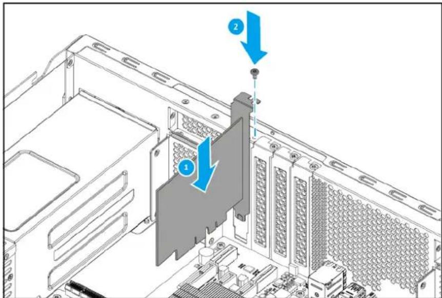
- Install fans onto the fan tray.
a. Align the holes in the fans to the screw holes on the fan tray.
b. Attach the screws that secure the fans to the fan tray.
Important
To ensure proper cooling, the correct side of the fan must be reattached so that the airflow is directed out of the rear panel. There may be an arrow on the side of the fan that indicates the airflow direction.
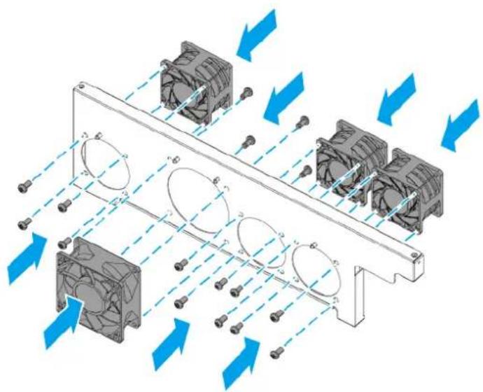
Note
- The pan head self-tapping D5x10 screws require a Phillips #2 screwdriver.
-
A torque of 5 kgf.cm (4.34 lbf.in) ± 0.5 kgf.cm (0.43 lbf.in) is recommended for electric screwdrivers.
-
Install the fan tray.
a. Insert the fan tray into the chassis.
b. Attach the screws that secure the fan tray to the chassis.

Note
- The flat head M3x4 screws require a Phillips #2 screwdriver.
- A torque of 5 kgf.cm (4.34 lbf.in) ± 0.5 kgf.cm (0.43 lbf.in) is recommended for electric screwdrivers.
c. Connect the power connectors of all fans to the system board.

- Attach the CPU fan duct.
a. Attach the CPU fan duct to the CPU fan.

b. Attach the bottom hooks of the CPU fan duct to the CPU heatsink screws.

- Attach the front top cover.
a. Place the front top cover on the device.
b.Slide the front top cover forward.
c. Attach the screws that secure the front top cover to the chassis.
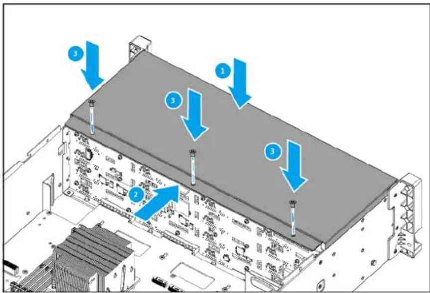
Note
- The flat head M3x4 screws require a Phillips #2 screwdriver.
-
A torque of 5 kgf.cm (4.34 lbf.in) ± 0.5 kgf.cm (0.43 lbf.in) is recommended for electric screwdrivers.
-
Attach the rear top cover.
a. Place the rear top cover on the device.
b.Slide the rear top cover forward.
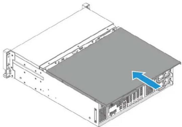
c. Tighten the screws that secure the rear top cover to the chassis.

- Slide each drive tray back into the NAS.
Important
Each drive must be returned to its original bay.

TS-h1677AXU-RP components and screws
Note
The information presented here apply only to the representative model of the NAS category. While all models within a NAS category have the same general structural design, their components and screws may differ in size, quantity, and other specifications.
Important
Recommended torque values are provided for electric screwdrivers. To avoid damage to the screw or component, the actual torque setting should not exceed ± 0.5 kgf.cm (0.43 lbf.in) of the recommended value, unless specified otherwise.

| No. Component (Quantity) | Screw Type (Quantity) | Screwdriver (Torque) | Attached To |
| 1 Rear top cover (1) | Thumb screw (2) | Tighten and loosen by hand | Chassis |
| 2 System fan (3) | Self-tapping D5x10 (4 x 3 = 12) | Phillips #2 (5 kgf.cm / 4.34 lbf.in) | Fan tray |
| 3 CPU fan (1) | Self-tapping D5x10 (4) | Phillips #2 (5 kgf.cm / 4.34 lbf.in) | Fan tray |
| 4 Handles (2) | Flat head M3x5 (3 x 2 = 6) | Phillips #2 (7 kgf.cm / 6.08 lbf.in) | Chassis |
| 5 Drive tray (3.5-inch) (4) | --- | ||
| 6 Backplane tray (1) | Flat head M3x4 (9) | Phillips #2 (5 kgf.cm / 4.34 lbf.in) | Chassis |
| 7 Chassis(1) | --- | ||
| 8 Expansion card slot cover(3) | Pan head M3x5 (1 x 3 = 3) | Phillips #2 (5 kgf.cm / 4.34 lbf.in) | Rear panel |
| 9 Fan duct(1) | -- System board | ||
| 10 Fan tray(1) | Flat head M3x4(2) | Phillips #2 (5 kgf.cm / 4.34 lbf.in) | Chassis |
| 11 Power supply cage(1) | Flat head M3x4(6) | Phillips #2 (5 kgf.cm / 4.34 lbf.in) | • Chassis (2 screws)• Rear panel (4 screws) |
| 12 Rear panel(1) | Flat head M3x4(11) | Phillips #2 (5 kgf.cm / 4.34 lbf.in) | Chassis |
| 13 Backplane(1) | Pan head M3x5(18) | Phillips #2 (7 kgf.cm / 6.08 lbf.in) | Backplane tray |
| 14 Front top cover(1) | Flat head M3x4(3) | Phillips #2 (5 kgf.cm / 4.34 lbf.in) | Chassis |
| 15 System board(1) | Pan head M3x5(19) | Phillips #2 (7 kgf.cm / 6.08 lbf.in) | Chassis |
| 16 Power supply unit(2) | --- |
8. Glossary
air shroud
Thin plastic covering for directing airflow from fans
backplane
A circuit board that serves as an extension to the system board. QNAP backplanes typically contain slots for connecting hard disk drives and solid-state drives with the use of drive trays.
central processing unit (CPU)
The main component in a computing device that executes instructions and processes data
circuit board
A hard, flat sheet with electrical connections printed on the surface. Examples of circuit boards include system boards, backplanes, and riser cards.
CPU fan
A fan for cooling the CPU (central processing unit)
drive cage
An enclosure within a QNAP device with slots for inserting and securing drive trays
drive tray
A tray for securely installing a drive on a QNAP device. The most common QNAP drive trays allow users to install 3.5-inch hard disk drives and 2.5-inch solid-state drives. Some device models have drive trays that can be locked with a key.
fan duct
Thin plastic covering for creating a tunnel to direct airflow from fans
flat head screw
A screw whose head has a tapered edge and a flat top that is level with the surface when fully screwed in
heatsink
A device with parallel fins that help transfer and dissipate heat from an electronic unit (such as a CPU or an M.2 SSD)
LCD display module
A unit containing an LCD panel and a supporting circuit board
mounting holes
Screw holes in circuit boards for attachment to a surface
pan head screw
A screw whose head has a straight edge and protrudes from the surface when fully screwed in
Phillips screwdriver
A screwdriver with a cross-shaped (+) point
positioning holes
Holes in a circuit board for stabilization on a surface before attaching screws. The holes fit onto specific positioning posts on the attachment surface.
positioning posts
Posts on a surface for stabilizing a circuit board before attaching screws to secure the circuit board to the surface. The posts align with specific positioning holes in the circuit board. Some positioning posts may also contain a screw hole for securing the circuit board with a screw.
power supply cage
An enclosure within a QNAP device for hot-swappable power supply units
power supply unit (PSU)
A component that converts alternating high voltage current (AC) into direct current (DC) for an electrical device. Some QNAP device models have redundant power supply units to maintain power in case the primary power supply unit fails.
riser card
A small circuit board that serves as an extension to the system board for installing expansion cards and modules
self-tapping screw
A screw that can create its own threads as it is driven into a material. Self-tapping screws are often used for attaching components made of materials softer than metal, such as plastic.
system board
Also known as motherboard. The system board is the main circuit board in a device where important system modules (such as the CPU) are located.
system fan
A fan for cooling internal components in a QNAP device
thumb screw
A screw that can be loosened and tightened by hand
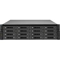

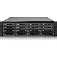
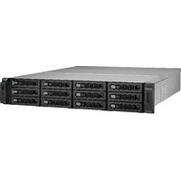

- INTRODUCTION
- CATEGORY A NAS MODELS
- CATEGORY B NAS MODELS
- CATEGORY C NAS MODELS
- CATEGORY D NAS MODELS
- CATEGORY E NAS MODELS
- GLOSSARY
- IMPORTANT INFORMATION
- ORIGINAL PACKAGING
- HARDWARE DEFECTS
- SAFETY INFORMATION
- GENERAL INSTRUCTIONS
- WARNING
- POWER
- MOVING PARTS
- SYSTEM BATTERY
- INGESTION HAZARD
- RAIL KITS
- IMPORTANT
- NAS MODEL CATEGORIZATION
- CATEGORY A
- CATEGORY B
- CATEGORY C
- CATEGORY D
- CATEGORY E
- CATEGORIZATION CRITERIA AND FLOW CHART
- REPAIR REQUIREMENTS
- RESOURCES
- NOTE
- DISASSEMBLING THE TS-453E
- REMOVE THE DRIVE CAGE
- REMOVE THE SYSTEM FAN
- REASSEMBLING THE TS-453E
- TS-453E COMPONENTS AND SCREWS
- OPTIONAL COMPONENTS
- DISASSEMBLING THE TS-AI642
- REMOVE ALL DRIVE TRAYS
- REMOVE THE CASE COVER
- REASSEMBLING THE TS-AI642
- TS-AI642 COMPONENTS AND SCREWS
- DISASSEMBLING THE TVS-H874T
- REMOVE THE REAR PANEL
- REMOVE THE BACKPLANE
- REASSEMBLING THE TVS-H874T
- ATTACH THE REAR PANEL
- ATTACH THE CASE COVER
- TVS-H874T COMPONENTS AND SCREWS
- DISASSEMBLING THE TVS-H1288X
- UNLOCK THE TRAYS
- 2.5-INCH DRIVE TRAY
- 3.5-INCH DRIVE TRAY
- REMOVE EXPANSION CARDS
- REMOVE THE CPU FAN TRAY
- TIP
- REASSEMBLING THE TVS-H1288X
- TVS-H1288X COMPONENTS AND SCREWS
- DISASSEMBLING THE TS-H1677AXU-RP
- REMOVE THE SYSTEM BOARD
- REASSEMBLING THE TS-H1677AXU-RP
- INSTALL THE BACKPLANE TRAY
- TS-H1677AXU-RP COMPONENTS AND SCREWS
- AIR SHROUD
- BACKPLANE
- CENTRAL PROCESSING UNIT (CPU)
- CIRCUIT BOARD
- CPU FAN
- DRIVE CAGE
- DRIVE TRAY
- FAN DUCT
- FLAT HEAD SCREW
- HEATSINK
- LCD DISPLAY MODULE
- MOUNTING HOLES
- PAN HEAD SCREW
- PHILLIPS SCREWDRIVER
- POSITIONING HOLES
- POSITIONING POSTS
- POWER SUPPLY CAGE
- POWER SUPPLY UNIT (PSU)
- RISER CARD
- SELF-TAPPING SCREW
- SYSTEM BOARD
- SYSTEM FAN
- THUMB SCREW
Brand : QNAP
Model : REXP-1200U-RP
Category : Disk array