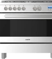
TFGC919X - Cooker Tisira - Free user manual and instructions
Find the device manual for free TFGC919X Tisira in PDF.


| Product Type | Freestanding Gas Cooker |
| Brand | Tisira |
| Model | TFGC919X |
| Width | 900 mm |
| Depth | 600 mm |
| Height | 850 mm |
| Weight | 65 kg |
| Fuel Type | Natural Gas (convertible to LPG) |
| Hob Type | 5-Burner Gas Hob |
| Wok Burner | Yes, 5.0 kW |
| Oven Type | Electric Fan Oven |
| Oven Capacity | 100 L |
| Energy Efficiency Class | A |
| Ignition | Electronic Ignition |
| Safety Features | Flame Failure Device, Child Lock, Overheat Protection |
| Cleaning | Easy-clean Enamel, Removable Oven Door |
| Warranty | 2 Years |
| Color | Stainless Steel |
| Timer | Yes, Digital Timer |
Frequently Asked Questions - TFGC919X Tisira
User questions about TFGC919X Tisira
0 question about this device. Answer the ones you know or ask your own.
Ask a new question about this device
Download the instructions for your Cooker in PDF format for free! Find your manual TFGC919X - Tisira and take your electronic device back in hand. On this page are published all the documents necessary for the use of your device. TFGC919X by Tisira.
USER MANUAL TFGC919X Tisira
IMPORTANT // Please ensure that you read through this user manual prior to installation and use. This manual contains important information to ensure optimal performance and keep you safe. Please retain your proof of purchase, as this will be required in the event that you require warranty service. Remember to retain this manual for future reference.
t tisira
HELLO
CONGRATULATIONS ON THE SELECTION OF THIS TISIRA APPLIANCE. TISIRA APPLIANCES HAVE BEEN SPECIFICALLY DESIGNED FOR AUSTRALIAN AND NEW ZEALAND KITCHENS.
Please read through this user manual carefully as it contains information that will ensure that your appliance is installed correctly, important operating & care instructions and also some advice of what you need to do if this appliance is not performing as intended.
CONTENTS
HELLO 2
CONTENTS 3
WARNINGS 4
OPERATING INSTRUCTIONS 5-16
MAINTAINING YOUR COOKER 17-19
INSTALLATION 20-23
CONNECTIONS 24-26
PRODUCT SPECIFICATIONS 27
TROUBLE SHOOTING 28-29
PROOF OF PURCHASE 30
NOTES 31
CONTACT DETAILS 32
WARNING & SAFETY INFORMATION
• DO NOT MODIFY THIS APPLIANCE.
- DO NOT SPRAY AEROSOLS IN THE VICINITY OF THIS APPLIANCE WHILE IT IS IN OPERATION.
- DO NOT STORE OR USE FLAMMABLE MATERIALS IN THE APPLIANCE STORAGE DRAWER OR NEAR THIS APPLIANCE.
- DO NOT FOR USE IN MARINE CRAFT, CARAVANS OR MOBILE HOME. (UNLESS EACH BURNER IS FITTED WITH A FLAME SAFEGUARD)
- WHERE THIS APPLIANCE IS INSTALLED IN MARINE CRAFT OR IN CARAVANS, IT SHALL NOT BE USED AS A SPACE HEATER.
- Servicing should be carried out only by authorised personnel.
- Do not remove the plug by pulling the cable.
- In order to prevent accidental tipping of the appliance, for example by a child climbing onto the open oven door, the anti-tilting chain must be installed.
Refer to the instructions on page 15.
- To avoid burns, young children should be kept away.
- This appliance is not intended for use by persons (including children) with reduced physical, sensory or mental capabilities, or lack of experience and knowledge, unless they have been given supervision or instruction concerning use of the appliance by a person responsible for their safety.
• Children should be supervised to ensure that they do not play with the appliance. - Accessible parts may become hot when the grill is in use. Children should be kept away.
- Very important: keep this instruction booklet with the appliance for handy references
- This appliance is designed for domestic use only.
- Keep packaging out of reach of children at all times.
OPERATING INSTRUCTIONS
INSTRUCTIONS FOR USE OF COOKTOP
DESCRIPTION OF SYMBOLS

Front Left Burner

Rear Left Burner

Rear Right Burner

Front Right Burner

Central Burner

USE THE CORRECT COOKWARE
- Cookware should be centralised on the burner when in use.
- Do not use round bottomed pans (e.g. woks) without appropriate wok support recommended by the manufacturer.
- Adjust the flame according to the size of your cookware, not allowing the flame to extend past the edge of the pan.
| Burner | Min ∅Saucepan(mm) | Max ∅Saucepan(mm) |
| Auxiliary 80 160 | ||
| Semi-rapid 120 | 200 | |
| Rapid 200 230 | ||
| Wok-Burner 230 | 260 |

OPERATING INSTRUCTIONS
- To ignite a burner, push in the knob and rotate anti-clockwise to the High Flame symbol.
- Keep the knob depressed for 3-4 seconds to ensure that the flame failure device keeps the burners lit.
- Adjust the heat level by rotating the knob between the Low Flame and High flame symbols.
- To turn the burner off, rotate the knob clockwise to the Off symbol.
When the burners are lit check that the flame is always regular. Before removing the saucepans turn the burners off.
There shall be adequate ventilation of the room when a rangehood is used at the same time as appliances burning gas. When a rangehood is not in use, ensure that natural ventilation outlets are open.

Be careful not to place saucepans with unstable or deformed bottoms on the burners to avoid overturning or spilling.
If a burner shuts off accidentally, turn off at the control knob and wait at least one minute to re-ignite it.
OPERATING INSTRUCTIONS
INSTRUCTIONS FOR USE OF OVEN
When adjusting or positioning your shelf, please ensure the following:
- Ensure that the shelf / tray is located between the two wire sideracks. (See point 1)
- The shelf stops should be facing downwards and towards the rear. (See point 2)
- The guard rail should always be located at the rear of the oven (See point 3)

BEFORE USING THE OVEN FOR THE FIRST TIME:
NOTE // After connecting the unit to the power, "12:00" is displayed on the digital timer but the time still needs to be set for the oven to work. Please refer to pages 10 and 11 for instructions on how to set the time.
USING THE THERMOSTAT CONTROL

Thermostat Control
- Set the temperature by turning the thermostat control to the desired level.
- When a temperature is selected, thermostat light will illuminate.
- When the selected temperature is reached, the light will turn off.
ATTENTION // During use, the appliance becomes hot. Care should be taken to avoid touching heating elements inside the oven.
NOTE // Never line the oven with aluminium sheets as this can cause damage to the enamel.
OPERATING INSTRUCTIONS
USING THE OVEN FUNCTION SELECTOR
| SYMBOL FUNCTION USE | ||
 | Light | The light mode can be turned on with no heating elements and will turn on with all oven functions. |
 | Defrost | Defrost mode distributes air at ambient temperature inside the oven to defrost food quickly and without protein adulterations. |
 | Fan-Assisted Gril | Fan-assisted Grill mode uses the grill element and oven fan to cook meats, vegetables and poultry. In this mode, heat is radiated down then spread throughout the oven. To achieve the best results, use the middle tray position. |
 | Double Grill | Double Grill mode should be used when maximum grill heat is not required. |
 | Grill | Grill mode should be used for melting cheese, toasting & browning. Five minutes preheating is required to heat the element. Use the upper shelf position for best results. |
 | Fan-Assisted Convection | Fan-assisted convection mode is ideal for delicate foods such as desserts. In this mode, the oven uses the oven fan, bottom and top elements. It is recommended to use the lower shelf position with this mode. |
 | Natural Convection | Natural Convection mode utilises the top and bottom elements. This function is recommended for use with the middle shelf position and is good for slow cooking casseroles, etc. |
 | Bottom Element | Bottom Element mode is recommended for cooking pastry based dishes (flans, quiches and tarts) that require more heat and radiation from below. |
 | Fan-Forced | Fan-forced mode cooks foods placed on up to 2 different shelves. |
![graph TD A["○"] --> B["○"] B --> C["○"] C --> D["○"] D --> E["○"] E --> F["○"] F --> G["○"] G --> H["○"] H --> I["○"] I --> J["○"] J --> K["○"] K --> L["○"] L --> M["○"] M --> N["○"] N --> O["○"] O --> P["○"] P --> Q["○"] Q --> R["○"] R --> S["○"] S --> T["○"] T --> U["○"] U --> V["○"] V --> W["○"]…](/content/2026/05/1074178/images/4af7e8292d64675eb11934213084c07b405c8889d4eed6931c1b90d99be8b16c.jpg)
OPERATING INSTRUCTIONS

DIGITAL TIMER
- Auto-Programming icon
- Time-setting icon
- Seconds icon
- Ready-to-use icon
- Alarm icon
- Number display
- Decrease key
- Mode key
- Increase key
Icon Function
| AUTO | Auto-programming icon Flashes when setting an automatic program, and at the end of an automatic program |
| P | Time-setting icon Flashes when setting the time |
| ● | Seconds icon Flashes in the time setting or alarm setting mode |
| ▲ | Alarm icon |
| ### | Ready-to-use icon Displays the status of the oven |
| -+ | Decrease and Increase keys Used to increase or decrease time |
| M | Mode key Used to change between program modes |
Term Meaning
| Present time Current 24-hour time at location (Eg. 12:00) | |
| Cooking time Duration of oven cooking time (Eg. 0:10 = 10 minutes cooking time) | |
| End time The time at the end of the cooking (Eg. 12:10) | |
| Automatic mode Sets the duration of the cooking time, beginning at 0:00(0:01 = 1 minute) | |
| Semi-automatic mode Sets the end time, beginning with the present time (24 hour time / 0:00 - 23:59) |
OPERATING INSTRUCTIONS
-
Once the oven has been turned on, '12:00' is displayed but the ready-to-use icon may not be displayed.
-
Press '-' or '+' to set the present time, or press the mode key to enter the present working mode. The relay contact is now connected and the ready-to-use icon will be displayed (A).

Display A
ALARM FUNCTION
To independently set the alarm:
- Press the mode key once, and the alarm icon will flash (B)

Display B
- Press '- or '+' to adjust the alarm clock time setting (0:01 = 1 minute). A few seconds after the time has been set, the alarm setting will apply and a countdown will begin from the set alarm time. (C)

- Once the alarm program has ended, the alarm icon will flash and the buzzer will sound. Press any key to stop the sounding of the alarm, otherwise, it will turn off automatically after 2 minutes and the display will return to the present time (D).

Display D
OPERATING INSTRUCTIONS
Press '-' or '+' to manually set the timer to "0"
AUTOMATIC/SEMI-AUTOMATIC PROGRAM MODE SETTING
- To enter the Automatic mode, press the 'mode key' twice (E)

- To enter the Semi-automatic mode, press the 'mode key' three times (F)

-
Use the ‘-’ and ‘+’ keys to adjust the cooking time (Automatic mode) or the end time (Semi-automatic mode)
-
A few seconds after the time has been set, the 'auto-programming indicator icon' will flash to confirm and apply your program setting (for both modes).
- Once the set automatic/semi-automatic program has ended, the display will return to the present time and the auto icon will no longer be displayed (Display D).
CANCEL FUNCTION
Press the '-' and '+' keys at the same time to cancel the set automatic or semi-automatic program. The display will return to the present time (D).
OPERATING INSTRUCTIONS
TABLE OF COOKING TIMES
The table below provides examples of the function, temperature, tray position and estimated cooking times for various types of food.
IMPORTANT // Please note that this table is a guide only and times can vary according to the type of food, volume and quantity of food being cooked.

Preheating of the oven is recommended for 10-15 minutes or until the oven thermostat light switches off to indicate that the selected temperature has been reached.
NATURAL CONVECTION
| Food to be cooked Tray Position Temperature (°C) Cooking time (mins) | |||
| BAKED GOODS | |||
| Small cakes 3 195 20-30 | |||
| Victoria sponge cake 3 190 25-35 | |||
| Swiss Roll 3 200 20-25 | |||
| Fruit Cake 2 155 120-180 | |||
| Scones 3 260 10-20 | |||
| Meringues 2 95 120-180 | |||
| Shortcrust Pastry 3 210 25-45 | |||
| Puff/Flaky Pastry 2 220 20-35 | |||
| Choux Pastry 3 220 25-35 | |||
| Biscuits 3 200 15-25 | |||
| Bread 2 250 30-40 | |||
| Pudding | 2 165 60-120 | ||
| Pizza | 3 270 | 25 | |
| Lasagne 3 170 | 75 | ||
OPERATING INSTRUCTIONS
NATURAL CONVECTION CONTINUED
| Food to be cooked Tray | Temperature (°C) | Cooking time (mins) | ||
| Position | ||||
| MEAT & POULTRY | ||||
| Beef (On the bone) | Rare & Crusty | mins per 500g | 270 12 mins | per 500g (+12 mins) |
| Rare 220 15 | (+15 mins) | |||
| Medium 220 20 mins per 500g (+20 mins) | (g +20 mins) | |||
| Well Done 180 | 25 mins per 500g (+25 mins) | |||
| Lamb | On the bone 220 | 20 mins per 500g (+20 mins) | ||
| De-boned and rolled | 170 27 mins | per 500g (+27 mins) | ||
| Pork | On the bone 220 | 3 25 mins per 500g (+25 mins) | ||
| De-boned and rolled | 180 | 30 mins per 500g (+30 mins) | ||
| Veal | On the bone | 220 | 25 mins per 500g (+25 mins) | |
| De-boned and rolled | 30 mins per 500g (+30 mins) | |||
| Chicken | 220 | 20 mins per 500g (+20 mins) | ||
| 170 | 25 mins per 500g (+15 mins) | |||
| Turkey/Duck | 220 | 20 mins per 500g (+20 mins) | ||
| 170 | 25 mins per 500g (+15 mins) | |||
FAN FORCED
| Food to be cooked Tray Position | Temperature (°C) | Cooking time (mins) | |
| BAKED GOODS | |||
| Small cakes | All Positions | 175 15-25 | |
| Victoria sponge cake 170 20-30 | |||
| Swiss Roll 180 15-20 | |||
| Fruit Cake 135 60-120 | |||
| Scones 210 8-15 | |||
| Meringues 80 60-120 | |||
OPERATING INSTRUCTIONS
FAN FORCED CONTINUED
| Food to be cooked Tray | Temperature (°C) | Cooking time (mins) | ||
| Position | ||||
| BAKED GOODS | ||||
| Shortcrust Pastry | 30 All Positions | 190 20-40 | ||
| Puff/Flaky Pastry 200 15-30 | ||||
| Choux Pastry 200 20-30 | ||||
| Biscuits 170 10-20 | ||||
| Bread 200 25-35 | ||||
| Pudding 150 60-120 | ||||
| Pizza 250 20 | ||||
| Lasagne 165 60 | ||||
| MEAT & POULTRY | ||||
| Beef (On the bone) | Rare & Crusty | 25 mins per 500g (+8 mins) | 230 9 mins | per 500g (+9 mins) |
| Rare 190 | 15 mins per 500g (+8 mins) | |||
| 20 mins per 500g (+10 mins) | ||||
| Medium 160 | g (+8 mins) | |||
| Well Done 190 | g (+10 mins) | |||
| Lamb | On the bone | 3 | 155 27 mins | per 500g (+14 mins) |
| De-boned and rolled | 200 25 mins | per 500g (+14 mins) | ||
| Pork | On the bone | 160 30 mins | per 500g (+18 mins) | |
| De-boned and rolled | 200 | 25 mins per 500g (+14 mins) | ||
| 30 mins per 500g (+14 mins) | ||||
| Veal | On the bone | 200 20 mins | per 500g (+10 mins) | |
| De-boned and rolled | 155 25 mins | per 500g (+13 mins) | ||
| Chicken | 220 18 mins | per 500g (+14 mins) | ||
| Turkey/Duck | 155 | 23 mins per 500g | ||
OPERATING INSTRUCTIONS
ACCESSORIES
The accessories can be inserted into the oven in 4 different shelf positions. They can be safely pulled two-thirds of the way out of the oven.

BAKING AND ROASTING SHELF
Accessory Description

Baking and roasting shelf

Enamelled baking tray

Rotary spit
Used for ovenware, cake tins, roasts, grilling and frozen meals
Used for moist cakes, pastries, frozen meals and large roasts. This accessory can also be inserted underneath the wire rack or rotary spit and used as a drip tray to collect fat
Used for roasts and large pieces of poultry. This accessory must be used only in combination with the enamelled baking tray.
INSTALLING THE ROTARY SPIT
The rotary spit functions only when the grill function is on.
PREPARING THE JOINT & POULTRY
Meat Joints
- Place the joint of meat as centrally as possible on the rotary spit and secure it at both ends with the retaining clips
- The joint may also be trussed with string
Poultry
- Bind the ends of the poultry wings underneath the back and the thighs against the body – this will prevent them from charring on the outside
- Pierce the skin on the underside of the wings to allow the fat to escape
OPERATING INSTRUCTIONS
INSERTING THE ROTARY SPIT
NOTE // Never touch the hot surface of the cooking compartment, the heating elements, the rotary spit or other accessories directly – they will be hot.
- Hook the spit holder into the bracket on the ceiling of the cooking compartment. If pre-heating is required, this should be done before pre-heating. Otherwise, thermal oven gloves must be worn during this process.

- To attach the spit, slide one end into the recessed adapter located in the left-hand side panel of the cooking compartment.

-
Hook the other end into the holder
-
Pour a little bit of water into the baking tray and slide this into shelf position 1 to collect the run-off fat.
REMOVING THE ROTARY SPIT
NOTE // Open the appliance door carefully – steam may escape
NOTE // Always wear heat-resistant gloves when handling hot accessories
- Open the appliance door, then carefully remove the rotary spit from the holder.

- Carefully withdraw the rotary spit from the recessed adapter located in the left-hand side panel of the cooking compartment and remove it from the oven.

- Remove the baking tray.
MAINTAINING YOUR COOKER
MAINTENANCE AND CLEANING
Before any operation disconnect the appliance from the power supply and wait for it to cool down.
- Do not use steam for cleaning
- Wash the enamelled parts with lukewarm water and detergent
- Wash the diffusers frequently with boiling water and detergent make sure to remove any deposits which could block the flame outlet
- Rinse the stainless steel parts well with water and dry them with a soft cloth
-
To clean the hob use slightly damp sponges and wiping cloths: if too much water is used it could penetrate the internal parts and damage electrical parts.
-
The trivets of the hob can be washed in the dishwasher
- For persistent stains use normal non-abrasive detergents, or hot vinegar
- Clean the glass parts with hot water and a soft cloth
- To prevent lighting difficulties, carefully clean the ignition candles regularly.
- It is necessary to clean the oven after each use
- Once the oven is cold, you will be able to remove the fat deposits with a sponge or a cloth damp with warm soapy water or a common detergent.
- Do not use harsh abrasive cleaners or sharp metal scrapers to clean this appliance.
ALWAYS CLEAN THE APPLIANCE IMMEDIATELY AFTER ANY FOOD SPILLAGE. TO MAINTAIN SAFE OPERATION, IT IS RECOMMENDED THAT THE PRODUCT BE INSPECTED EVERY FIVE YEARS BY AN AUTHORISED SERVICE PERSON.
MAINTAINING YOUR COOKER
REMOVAL AND INSERTION OF THE SIDE RACKS

-
To remove the hook-in racks, take hold of the rack and lift it upwards and outwards to unhook the rack from its position.
-
To re-insert the rack, sit the rack onto the nut located at the bottom (A) then insert the top hooks of the rack into the slots on the oven wall (B)
REPLACING THE OVEN LAMP

After the oven is disconnected from the mains and has cooled down replace the lamp as follows:
- Unscrew the glass protection cap
- With a soft cloth, unscrew the light bulb
- With a soft cloth, replace the bulb (E14 25W 300°C)
- Re-secure the glass protection cap
WARNING // It is important not to touch the bulb with your hands as acids from your skin can damage the bulb.
WARNING // Ensure that the appliance is switched off before replacing the bulb to avoid the risk of electric shock.
MAINTAINING YOUR COOKER
REMOVING THE INTERIOR GLASS OF THE OVEN
To remove the interior glass of the oven door for cleaning purposes:
- Position the oven door into a semi-open position

- Remove the screws located at the top of the door

- Use both hands to carefully remove the interior glass

- After cleaning, refit the glass by carefully inserting the interior glass back into the door with both hands, re-inserting the screws, and closing the oven door as normal
CLEANING THE OVEN DOOR
For a more thorough clean, the oven door can be removed by proceeding as follows:
- Open the door fully
- Lift up the small levers "A" located on the two hinges
- Grip the door on the two external sides and close the door slowly until it reaches the levers. Ensure that the levers are locked onto slots "B". As shown below
-
Using both hands, push the oven door lightly inwards to enable the door hinges "C" to come away from the slots "D" (see Fig 5D) and pull the door towards you until it is released from the oven
-
To replace door, reverse this sequence


INSTALLATION
The manufacturer declines any and all responsibilities for damages to things or injuries to persons or animals deriving from incorrect installation or use of the equipment.
INSTRUCTIONS FOR INSTALLATION
WARNING:
- Prior to installation, ensure that the local distribution conditions [nature of the gas and gas pressure] and the adjustment of the appliance are compatible
- The adjustment conditions for this appliance are stated on the data plate or under the product specifications section on page 27
- The appliance should have adequate surrounding ventilation for complete combustion of gas, proper fluing, and to maintain temperature of immediate surroundings within safe limits.
- This appliance shall be installed only by authorised persons and in accordance with the manufacturer's installation instructions, local gas fitting regulations [AS5601], municipal building codes, electrical wiring regulations, and local water supply regulations.

A = 95-160mm
INSTALLATION
REINFORCEMENT BAR/ ADJUSTABLE FEET INSTALLATION
- Before proceeding, remove all the temporarily fixed parts and accessories of the oven (pan supports, burners etc.). Retrieve the two reinforcement bars that are provided with the appliance and remove them from the packaging.

-
Carefully tilt the appliance by raising one side slightly from the floor. This task may require two operators.
-
With the cooker safely tilted, position the two reinforcement bars onto the left and right side of the bottom of the cooker (where the screw holes on each bar align with the mounting holes on the bottom of the cooker).

- Using a screwdriver, fix both reinforcement bars into the mounting holes using the screws provided as shown in the image. There are 4 screws for each reinforcement bar.

- Firmly screw each of the four legs into their cavities.


- Carefully realign the cooker to its original vertical position, and adjust the legs to level the appliance. This task may require two operators.

INSTALLATION
INSTALLING THE ANTI-TILTING CHAIN
The cooker is supplied with 2 anti-tilting chains to prevent the appliance from tilting forward and accidentally damaging the gas pipe. The anti-tilting chain should be fitted as follows:
- Drill four 6mm holes in the wall
- Insert part "R" into the holes then screw in the "screw eyes" part "G"
Note // If the part provided is not suitable for the wall material please use an appropriate device to ensure secure holding of the "screw eyes" to the wall.
- Bring the cooker to the wall and clip the chains on the "screw eyes".
In situations where the cooker is installed between two cabinets:
- Drill a 16mm hole in each cabinet, at the same height as the chain.
- Feed the chain through the left and right holes respectively.
- Move cooker to desired position.
- Tighten and fix chains to back-side of cabinet.

G R Hole

INSTALLATION

COMBUSTIBLE SURFACES
Any adjoining wall surface (side or rear) situated within 200mm from the edge of any hob burner must be a suitable noncombustible material for a height of 150mm for the entire length of the cooker.
Any combustible construction above the cooker must be at least 650mm above the maintop.
STABILITY BRACKET INSTALLATION
- Carefully move the appliance to expose the back wall against which the appliance stands. This may require two people.
- Fix the stability bracket onto the wall using the two screws provided. Ensure that this bracket is placed in alignment with the slot located at the rear of the appliance.
- Carefully move the appliance back to its original position to align the wall bracket into the slot located at the rear of the appliance.
- The dotted line on the image illustrates where the cooker should be positioned once the stability bracket has been installed.

CONNECTIONS
ELECTRICAL CONNECTION
Equipment type: Free standing (Class 1) Insulation class: Class 1
The appliance is fitted with an approved 15 Amp flexible cord and plug which must be connected to a correctly earthed socket outlet.
CONNECTION OF THE SUPPLY CABLE TO THE MAINS
In case of a direct connection to the mains (cable without plug), it is necessary to insert a suitable omnipolar switch before the appliance, with minimum opening between contacts of 3 mm (the grounding wire should not be interrupted by the switch).
Before connecting to the mains, make sure that:
- All components used to make the electrical connection are adequate to withstand the maximum load required (see rating plate).
- The supply system is regularly grounded, according to the regulations in force.
- The socket or the omnipolar switch can easily be reached after the installation of the oven.
WIRE COLOURS:
Green & Yellow - Earth
Blue - Neutral
Brown - Live


WARNING // Never use reductions, shunts, adaptors which can cause overheating or burning.
NOTE // After carrying out the connection to the mains, check that the supplying cable does not come into contact with parts subject to heating.
ATTENTION // If the supply cord is damaged, it must be replaced by the manufacturer, its service agent or similarly qualified persons in order to avoid a hazard.
CONNECTIONS
GAS CONNECTION
The gas connection is male 1/2" BSP and is situated 55mm from the right and 700mm from the floor.
Loosen the tie-in down and connect one terminal of the pipe with the gas elbow between 1-1.2m long.
The hose should not be subjected to abrasion, kinking or permanent deformation and should be able to be inspected along its entire length after installation.
Unions compatible with the hose fittings must be used and connections tested for gas leaks.
The flexible tube shall be fitted in such a way that it cannot come into contact with a moveable part of the housing unit (e.g. a drawer) and does not pass through any space susceptible of becoming congested.
The fixed consumer piping outlet should be at approximately the same height as the cooker connection point, pointing downwards and approximately 150mm to the side of the cooker.
The hose should be clear of the floor when the cooker is in the installed position.
Once the appliance has been installed, make sure that the gas pipe is neither squashed or damaged by moving parts.
Before switching the appliance on, check that it is correctly regulated for the type of gas available.
ADJUSTMENT TO DIFFERENT GAS TYPES
To perform the adjustments to different types of gas, the qualified installer shall follow the instructions given on this section.
Make sure that the gas supply pressure respects the values presented in the table “Gas Specifications” on page 27.
NATURAL GAS
This appliance leaves the factory set to operate using Natural Gas.
Make sure that the Natural Gas regulator supplied with the appliance is installed and, with all burners operating at their maximum, adjust the test point pressure to 1kPa.
UNIVERSAL LPG
To convert from Natural Gas to Universal LPG, ensure that the Natural Gas regulator is replaced by the Test Point Assembly supplied with the appliance.
An approved gas regulator suitable for a supply pressure of 2.75kPa should be part of the gas tank supply.
IMPORTANT // Ensure that the gas injectors are also replaced with the Universal LPG injectors supplied. Refer to the Gas Specification table on page 27 for the injectors.
- Remove the trivets
- Remove the burners caps and diffusers
- With a 7 mm socket spanner unscrew and remove the injectors.


-
Replace the injectors with those supplied suitable for Universal LPG
-
Replace the burner difusers, caps and trivets
CONNECTIONS
SETTING THE MINIMUM FLAME
The flame on the small output is regulated by the factory.

When the injectors have been replaced or there are special mains pressure conditions, it may be necessary to regulate the minimum flame again. The operations necessary to set the minimum flame are as follows:
- Light the burner.
- Turn the knob to the minimum position.
- Take out the knob (and gasket if there is one).
-
LPG to Natural Gas: use a thin blade screwdriver to turn the bypass screw located on the body of the gas tap as shown on the image above. Turn the bypass screw gently clockwise to the end completely then turn it anti-clockwise 1 turn for the triple ring, 3/4 turn for the rapid, 1/2 turn for the semi-rapid and 3/8 turn for the auxiliary.
-
Natural Gas to LPG: use a thin blade screwdriver to turn the bypass screw located on the body of the gas valve shaft as shown on the image above. Turn the
by-pass screw gently clockwise to the end.
- Put the knob back on and turn it quickly from the maximum position to the minimum position, checking that the flame does not go out.
- For burners with safety valve make sure that the regulation obtained is sufficient to maintain heating of the thermocouple. If it is not, increase the minimum.
Before leaving, check all connections, with soap and water, for gas leaks.
WARNING // Do not use a naked flame for detecting leaks.
Ignite all burners both individually and combined to ensure correct operation of gas valves, burners and ignition.
ABNORMAL OPERATION
If the appliance cannot be adjusted to perform correctly, it is an abnormal situation and you should contact the authorised service provider.
Any of the following are considered to be abnormal operation and may require servicing:
- Yellow tipping of the burner flame.
- Sooting up of utensils.
- Burners not igniting properly.
- Burners failing to remain alight.
- Burners being extinguished by oven door.
• Gas valves which are difficult to turn.
PRODUCT SPECIFICATIONS
GAS SPECIFICATIONS
| NATURAL GAS UNIVERSAL LPG | ||||||
| Inj. Diam.(mm) | Power(MJ/h) | Gas pressure(kPa) | Inj. Diam.(mm) | Power(MJ/h) | Gas pressure(kPa) | |
| Auxiliary 0.90 4.00 | 1 | 0.53 3.70 | 2.75 | |||
| Semi Rapid | 1.20 7.10 | 0.73 7.10 | ||||
| Rapid 1.50 | 11.00 | 0.95 11.70 | ||||
| Wok 1.63 | 12.70 1.00 | 13.00 | ||||
ELECTRICAL SPECIFICATIONS
| MODEL VOLTAGE WATTAGE | ||
| TFGC919X 220-240V~50Hz 2940W | ||
* 15 Amp Plug
TROUBLE SHOOTING
PROBLEM SUGGESTED SOLUTION
| The burner is not burning properly | Check if the burner is dirty or damp - Try cleaning and/or drying the burner.The appliance may not be suitable for the type of gas you are utilizing - Check the identification plate on the back of the unit. |
| The burner does not ignite | Ensure that the power is on –First check if the main house fuse or circuit breaker has activated.Then, test the power socket with another appliance. If the appliance works, unplug the cooker and contact the service agent.Check if the burner is dirty or damp. The electrode or burner slots may be blocked by debris - Try cleaning and/ or drying the burner.Check if there is a problem with your gas supply – make sure any other gas appliances you may have are working.Ensure the burner caps are correctly positioned |
| The appliance is producing too much heat and moisture in the room | Ensure that the kitchen is well ventilated – keep natural ventilation holes open or install a mechanical ventilation device. |
| The oven is not functioning | Ensure that the appliance is switched on at the mainsCheck that the appliance is not programmed to turn on later. If it is, switch to manual setting mode on your oven.If the button or scale on the timer remains in the automatic position after use, the power supply to the oven will be interrupted.Check for an unexpected power outage – Switch on adjacent lights and check the fuses and plug wiring. |
TROUBLE SHOOTING
PROBLEM SUGGESTED SOLUTION
| The light bulb is not functioning | Check if the bulb is loose or burned out – if this is the case, either re-fix the bulb properly or replace the bulb. (Refer to “Replacing the oven lamp” on page 18 of the User Manual) |
| There is smoke coming from the oven | If the oven is relatively new, this may be due to the protective oil on the elements.Otherwise, the smoke may be caused by the oil or fat that has deposited onto the elements during the cooking.Continued use of the oven will burn away the residuesTo prevent this issue, shield the food with foil or keep it further away from the elements (particularly when grilling) |
| The clock timer is not functioning | Ensure that the appliance is switched on at the mains.Check for an unexpected power outage – Switch on adjacent lights and check the fuses and plug wiring.Follow the step by step operating instructions on the digital timer given on pages 10 and 11. |
PROOF OF PURCHASE
ATTACH YOUR PROOF OF PURCHASE FOR FUTURE REFERENCE
NOTES
CONTACT DETAILS
AUSTRALIA
ARISIT PTY LIMITED
40-44 Mark Anthony Drive, Dandenong South, VIC 3175, Australia
© P // 1300 762 219
F // 03 9768 0838
consumer.care@arisit.com
NEW ZEALAND
ARISIT PTY LIMITED
PO Box 68-140 Newton, Auckland 1145, New Zealand
P // 09 306 1020
F // 09 302 0077
sales@aristonappliances.co.nz
TISIRA IS COMMITTED TO ONGOING RESEARCH AND DEVELOPMENT. EVERY EFFORT HAS BEEN MADE TO ENSURE ALL INFORMATION IN THIS USER MANUAL IS CORRECT AT TIME OF GOING TO PRINT. DIMENSIONS SHOULD BE USED AS A REFERENCE ONLY AND ACTUAL DIMENSIONS SHOULD BE TAKEN FROM THE PHYSICAL PRODUCT ONLY.
MANUFACTURER RESERVES THE RIGHT TO CHANGE SPECIFICATIONS WITHOUT NOTICE.
t tisira
- HELLO
- CONGRATULATIONS ON THE SELECTION OF THIS TISIRA APPLIANCE. TISIRA APPLIANCES HAVE BEEN SPECIFICALLY DESIGNED FOR AUSTRALIAN AND NEW ZEALAND KITCHENS
- CONTENTS
- WARNING & SAFETY INFORMATION
- OPERATING INSTRUCTIONS
- INSTRUCTIONS FOR USE OF COOKTOP
- DESCRIPTION OF SYMBOLS
- USE THE CORRECT COOKWARE
- INSTRUCTIONS FOR USE OF OVEN
- BEFORE USING THE OVEN FOR THE FIRST TIME
- DIGITAL TIMER
- ALARM FUNCTION
- AUTOMATIC/SEMI-AUTOMATIC PROGRAM MODE SETTING
- CANCEL FUNCTION
- TABLE OF COOKING TIMES
- ACCESSORIES
- BAKING AND ROASTING SHELF
- ACCESSORY DESCRIPTION
- INSTALLING THE ROTARY SPIT
- PREPARING THE JOINT & POULTRY
- MEAT JOINTS
- POULTRY
- INSERTING THE ROTARY SPIT
- REMOVING THE ROTARY SPIT
- MAINTAINING YOUR COOKER
- MAINTENANCE AND CLEANING
- REMOVING THE INTERIOR GLASS OF THE OVEN
- CLEANING THE OVEN DOOR
- INSTALLATION
- INSTRUCTIONS FOR INSTALLATION
- WARNING
- REINFORCEMENT BAR/ ADJUSTABLE FEET INSTALLATION
- INSTALLING THE ANTI-TILTING CHAIN
- COMBUSTIBLE SURFACES
- STABILITY BRACKET INSTALLATION
- CONNECTIONS
- ELECTRICAL CONNECTION
- CONNECTION OF THE SUPPLY CABLE TO THE MAINS
- GAS CONNECTION
- ADJUSTMENT TO DIFFERENT GAS TYPES
- NATURAL GAS
- UNIVERSAL LPG
- SETTING THE MINIMUM FLAME
- ABNORMAL OPERATION
- PRODUCT SPECIFICATIONS
- ELECTRICAL SPECIFICATIONS
- TROUBLE SHOOTING
- PROOF OF PURCHASE
- NOTES
- CONTACT DETAILS
- ARISIT PTY LIMITED
Brand : Tisira
Model : TFGC919X
Category : Cooker