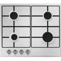
TGF64E - Cooker Tisira - Free user manual and instructions
Find the device manual for free TGF64E Tisira in PDF.


| Product Type | Freestanding Cooker |
| Brand | Tisira |
| Model | TGF64E |
| Energy Source | Gas (hob), Electric (oven) |
| Dimensions (H x W x D) | 900 x 600 x 600 mm |
| Weight | 65 kg |
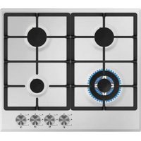
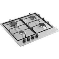
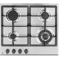
| Hob Type | 4 Gas Burners |
| Oven Capacity | 65 L |
| Oven Functions | Conventional, Grill, Fan (optional) |
| Power Supply | 220-240 V, 50/60 Hz (oven & ignition); Gas (hob) |
| Energy Class | A |
| Finish | Stainless Steel |
| Cleaning | Enamel Interior, Removable Door, Drip Tray |
| Safety Features | Flame Failure Device, Overheat Protection |
| Child Lock | Yes (control panel lock) |
| Number of Oven Shelves | 2 |
| Oven Light | Bulb (25 W) |
| Gas Connection | Natural Gas or LPG (convertible) |
| Spare Parts Available | Burner Caps, Grates, Heating Elements, Thermostat |
Frequently Asked Questions - TGF64E Tisira
User questions about TGF64E Tisira
0 question about this device. Answer the ones you know or ask your own.
Ask a new question about this device
Download the instructions for your Cooker in PDF format for free! Find your manual TGF64E - Tisira and take your electronic device back in hand. On this page are published all the documents necessary for the use of your device. TGF64E by Tisira.
USER MANUAL TGF64E Tisira
IMPORTANT // Please ensure that you read through this manual prior to installation and use. This user manual contains important information to ensure optimal performance and keep you safe. Please retain your proof of purchase, as this will be needed in the event that you require a warranty service. Remember to keep this user manual for future reference.
t tisira
Version 1.1
www.tisira.com
Content
Contents 2
Warning & Safety Instructions 3
Product Overview 4 - 5
Operating Instructions 6 - 7
Cleaning & Maintenance 8
Installation 9 - 15
Warning & Safety Instructions
IMPORTANT // To ensure best performance, avoid risk of damage or accidents. Please read the operating instructions prior to first time use.
Important Safety Instructions
To maintain the efficiency and safety of this appliance, we recommend that you do the following:
• DO NOT USE OR STORE FLAMMABLE MATERIALS NEAR THIS APPLIANCE.
- DO NOT SPRAY AEROSOLS IN THE VICINITY OF THIS APPLIANCE WHILE IT IS IN OPERATION.
• DO NOT MODIFY THIS APPLIANCE.
- This appliance is not intended for use by persons (including children) with reduced physical, sensory or mental capabilities, or lack of experience and knowledge, unless they have been given supervision or instruction concerning use of the appliance by a person responsible for their safety.
- Young children should be supervised to ensure that they do not play with the appliance.
- Ensure adequate ventilation i.e. the use of a rangehood when cooktops / other appliances, burning gas or other fuels are in use.
- If the supply cord of this equipment is damaged, it must only be replaced by the manufacturer or its service agent or a similarly, qualified person in order to avoid a hazard.
- This appliance has been designed for indoor domestic use only.
• NOT FOR USE IN MARINE CRAFT, CARAVANS, OR MOBILE HOMES.
- Keep packaging out of reach of children at all times. To avoid burns, young children should be kept away.
- This appliance is designed for domestic use or use in similar environments by guests in hotel or motel rooms, bed & breakfasts and other typical living quarters. This does not include common/ shared or commercial facilities within hotels, motels or bed & breakfasts.
- NOTICE // The manufacturer may not be held responsible for any damage caused by incorrect installation or non-compliance with the instructions in this manual.
Product Overview
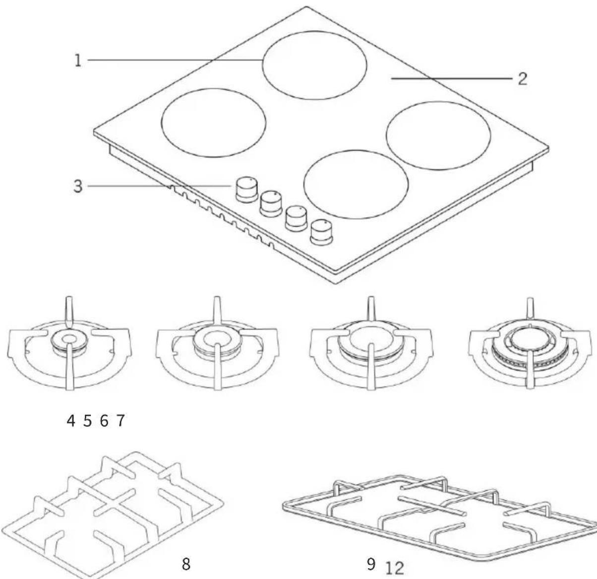
- Burner positions
- Glass or Metal Surface
-
Control Buttons
-
Small Burner
- Medium Burner
- Large Burner
7.WOK Burner
8. Cast Grill
9. Enamel Grill
Product Overview
Burners
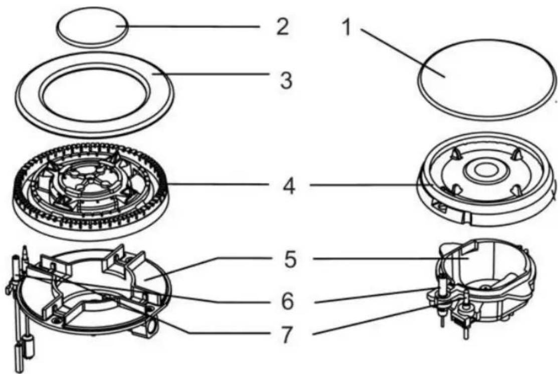
- Burner cap
- Inner burner cap
- Outer burner cap
-
Burner head (diffuser)
-
Burner base (cup)
- Ignition candle
- Flame failure device (thermocouple)
Operating Instruction
IMPORTANT // To ensure best performance, avoid risk of damage or accident. Please read the operating instructions prior to first time use.
This appliance is supplied with a spare data plate label. Please attach it to an adjacent surface for future reference if the labels on the base of the cooktop are not visible after installation.
NOTE // The metal components have a protective coating, which may give off a slight smell when heated up for the first time. This smell and any vapors given off do not indicate a faulty gas connection or appliance nor are they health hazardous.
The burners differ in size and power. Choose the most appropriate burner for the diameter of the cookware being used as specified on the table below:
| BURNER | PAN SIZES | |
| min diameter (mm) | max diameter (mm) | |
| Auxiliary | 120 | 180 |
| Semi-Rapid | 180 | 200 |
| Rapid | 180 | 220 |
| Wok | 220 | 260 |
The position of the corresponding gas burner is indicated on each control knob.
1. Control knobs
The control knob is used to ignite the burner and regulate the strength of the flame.

flowchart
graph TD
    A["Start"] --> B{Condition}
    B --> C["Loop Back"]
    C --> D["End"]
● The gas supply is turned off
Ignition candle
Strongest flame
Weakest flame
■ Respective burner
ATTENTION // Operating the knob controls as described below can cause damage to the appliance:
- Switching on the burner without pressing the control down.
- Switching on the burner by turning the control clockwise.
- Switching the burner off by turning the control anti-clockwise.
2. Lighting a burner
To light a burner, simply follow the steps:
- Press the corresponding knob of the burner you are about to use all the way in and, then, turn it anti-clockwise until you reach the ‘Strongest Flame’ symbol.
- Keep the knob pressed in for a few seconds after the flame ignites.
Operating Instruction
NOTE // When one of the control knobs is activated, sparks are generated on all burners of the cooktop simultaneously.
CAUTION // If the flame is extinguished unintentionally, turn off the gas with the control knob, wait for at least 30 seconds for the gas to dissipate and try to light it again.
3. Switching off
To turn off a burner, simply turn the knob clockwise until it stops under the OFF symbol “●”.
This stops the flow of gas and the flame goes out.
4. Interruption to the electricity supply
In the event of a power cut the flame can be ignited with a match by following the steps:
- Press the corresponding knob of the burner you are about to use all the way in, then turn it anti-clockwise until you reach the 'Strongest Flame' symbol.
- While pressing the control knob in, light the gas at the burner with a match.
- Keep the knob pressed in for a few seconds after the flame ignites.
5. Regulating the flame
IMPORTANT // Adjust the flame intensity so that it does not spread out beyond the side of the pan. The tips of the flames are much hotter than the centre, so they should stay beneath the pan base for a best efficiency and a lower risk of injuries and damages on pan handles.
The flame can be regulated for any level between the strongest and weakest flame symbols.
- Cookware should be positioned aligned with the centre of the burner.
- Do not use round-bottomed pans (eg. Woks) without an appropriate wok support recommended by the manufacturer.

6. Flame failure device
This appliance is fitted with a thermo-electric flame failure safety device that cuts off the supply of gas to a burner if the flame goes out, for example, when water boils over the burners or sudden draughts occur.
The flame failure device operates independently from the electricity supply. This means that it will still work if the cooktop is used during a power cut.
Cleaning & Maintenance
IMPORTANT // Before cleaning your oven, or performing maintenance, turn the appliance off and disconnect it from the power supply. Also allow the appliance to cool down before touching the unit.
Cleaning your appliance frequently will extend its life. When cleaning your gas cooktop:
- Do not use a steam cleaning appliance to clean this appliance.
- Use a soft cloth, warm water and neutral soap to clean enameled, cast iron and stainless steel parts.
- Use a soft dry cloth to dry surfaces that have been cleaned with water. This will prevent the occurrence of watermarks and limescale deposits.
- Do not use cleaning products containing descaling agents.
- Do not use hard, abrasive brushes or sponges.
NOTE // Always clean the appliance immediately after any food spillage.
Cleaning the Burners
The removable parts of the burners can be disassembled for a more thorough cleaning.
-
Remove the burner caps and burner diffusers by pulling them away from the burner cup.
-
Soak them in hot water with a small amount of washing detergent.
- Softly scrub off any remaining pieces of food.
- Rinse the parts, wipe and dry them.
- Wipe the fixed parts of the burner cup with a damp cloth, drying it afterwards with a dry cloth.
- Before placing the burner cap and diffuser back in position, make sure that the flame apertures are clean and completely dry.
IMPORTANT // Make sure that the ignition candle and the probe of the thermo-electric flame failure device extend through their respective holes in the burner diffuser. Once the burner diffuser is clicked into place correctly, place the burner cap on top of it. The burner cap should not rotate when correctly positioned.
Servicing the cooktop
Always refer servicing to an authorised service person. It is recommended that the appliance be serviced every five years to ensure the cooktop continues to operate correctly and safely.
NOTE // If the appliance cannot be adjusted to perform correctly, it is an abnormal situation and you should contact the authorised service provider.
Installation
IMPORTANT // This unit must be installed by authorised personnel and used only in permanently ventilated rooms in accordance with the requirements of AS 5601 (gas installations), wiring code, manufacturer's instructions, local and national authority and any other statutory regulations.
Follow carefully the safety instructions and clearance requirements given below.
NOTE // The dimensions presented in this manual are given in millimetres (mm).
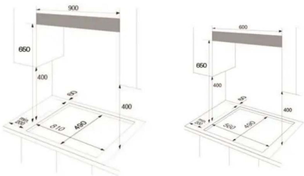
IMPORTANT // The veneer or laminate coatings of worktops (or adjacent kitchen units) must be treated with 100 °C heat-resistant adhesive which will not dissolve or distort.
A minimum safety clearance of 25mm underneath the cooktop must be provided for the installation of the flexible gas connection hose and mains flexible power cord.

Installation
600mm Hobs - The Gas inlet (1) is located underneath the appliance towards the rear edge. The Electrical terminal (2) is also located underneath the appliance approximately in the centre of the rear edge.

Installation Accessories Supplied
The following installation accessories are supplied with the appliance:
4 x mounting brackets and screws
1 x seal strip
1 x natural gas regulator
4 x ULPG Injectors
IMPORTANT // The gas supply connection point shall be accessible with the appliance installed.
Installation
Installation Procedure
- Make the benchtop cut-out for the cooktop in accordance with the diagrams previously presented in this manual.
- Remove trivets, gas burner caps and diffusers.
- Turn the cooktop upside down resting it on a cloth.
NOTE // Be careful not to damage the ignition candles and the probes of the flame failure device during this process.
- Apply the self-adhesive seal strip onto the edges of the cooktop that will be resting on the benchtop. (Do not overlap the ends of the seal strip)

natural_image
Illustration of a hand holding a pen near a screen, with a black X mark on the floor (no text or symbols)NOTE // Do not use any joint sealant. The appliance's sealing strip ensures a sufficient seal between the appliance and the benchtop.
- Feed the flexible power cord down through the cut-out.
- Place the cooktop in the cut-out without securing it.
- Connect the appliance to the mains electricity supply (refer to the 'Electrical Connection' section).
-
Connect the appliance to the gas supply (refer to the 'Gas Connection' section).
-
Secure the appliance by matching the screws with the correspondent screw holes in each bottom corner of the cooktop.

- Once the gas cooktop has been installed it is essential to check that neither the gas pipe nor the electricity cable is in contact with hot parts of the appliance or hot gas exhaust.
NOTE // A full operational test and a test for possible leakages must be carried out by the installer before leaving. Check all burner flames are blue in colour, stable and completely ignite at both high and low flame settings with no appreciable yellow tipping, carbon deposition, lifting, floating lighting back or objectionable odour. Test burners individually and in combination.
Electrical Connection
IMPORTANT // Electrical connections should be carried out by a suitably qualified and competent person in strict accordance with the wiring rules and national and local safety regulations.
Installation
ATTENTION // If the connection cable is damaged, it must be replaced by a suitably qualified electrician.
The supply cord has been fitted with a 10A three-pin plug and is designed for use with alternating current according to the indications on the rating label (data plate) located underneath the cooktop.
Before actual connection make sure that:
- The fuse and electrical system can withstand the load required by the appliance.
- The electrical supply system is equipped with an efficient earth hook-up according to the norms and regulations prescribed by law.
- The plug and switch are easily accessible after installation.
The wires in the mains lead are coloured in accordance with the following code:
Green & Yellow - Earth
Blue - Neutral
Brown - Live
As the colours of the wires in the mains lead of this appliance may not correspond with the coloured markings identifying the terminals in your plug, proceed as follows:
- The green and yellow wire must be connected to the terminal in the plug that is marked with the letter E or by the earth symbol or coloured green or green and yellow.
• The blue wire must be connected to the
terminal that is marked with the letter N or coloured black.
- The brown wire must be connected to the terminal that is marked with the letter A or coloured red.
NOTE // This appliance must be earthed.
Gas Connection
IMPORTANT // Gas connections should be carried out by a suitably qualified and competent person in strict accordance with the requirements of AS 5601 (gas installations) and national and local regulations.
This gas cooktop can be connected with a class B or D flexible hose, which complies with AS/NZS 1869 and must be certified. The min. inner ∅ must be 10 mm and the maximum length 1.2 m. Make sure it does not touch moving parts of the kitchen furniture, e.g. a drawer. Ensure the hose assembly is not exposed to high temperatures exceeding the maximum recommended by the hose manufacturer, subjected to strain, kinking, permanent deformation or damage by vermin.
This appliance is factory fitted with Natural Gas Injectors and is also supplied with a ULPG conversion kit. The conversion of the appliance to be used with ULPG must be undertaken by qualified personnel. Please refer to the ‘Gas Conversion – Natural Gas / ULPG’ section.
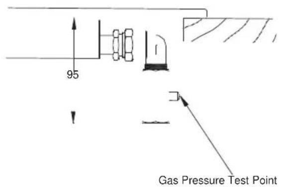
A Pressure Test Point is provided on the gas regulator. (supplied for natural gas)
Installation
The Gas pressure must be set by an approved gas fitter as shown on the table presented on the next page or, alternatively, on the appliance data plate:
Natural gas 1.0 kPa ULPG 2.75 kPa
-
Loosen the screw in the test point until it is free in its housing. The screw is retained in this position.
-
Connect the hose from the pressure gauge.
- Reassemble one of the large burners, turn on the gas and manually light the burners.
- Disconnect gauge and screw in the test point screw.
NOTE // The Gas Regulator must be set with the largest burner operating at maximum setting.

Installation
Gas Consumption and Injectors Specifications
| TGF64E | Natural Gas | Universal LPG | ||||
| Inj. diam. (mm) | MJ/h | Gas pressure | Inj. diam. (mm) | MJ/h | Gas pressure | |
| Rapid burner x 1 | 1.55 | 12.00 | 1.0kPa | 0.85 | 10.00 | 2.75kPa |
| Semi-rapid burner x 2 | 1.18 | 7.00 | 1.0kPa | 0.65 | 5.50 | 2.75kPa |
| Auxiliary burner x 1 | 0.90 | 4.00 | 1.0kPa | 0.50 | 3.30 | 2.75kPa |
| Total NHGC | 30.00 | 24.30 | ||||
| TGWF64E | Natural Gas | Universal LPG | ||||
| Inj. diam. (mm) | MJ/h | Gas pressure | Inj. diam.(mm) | MJ/h | Gas pressure | |
| WOK burner x 1 | 1.68 | 12.60 | 1.0kPa | 0.96 | 12.50 | 2.75kPa |
| Semi-rapid burner x 1 1.18 | 7.00 | 1.0kPa | 0.65 | 5.50 | 2.75kPa | |
| Semi-rapid burner x 1 | 1.18 | 7.00 | 1.0kPa | 0.65 | 5.50 | 2.75kPa |
| Auxiliary burner x 1 | 0.90 | 4.00 | 1.0kPa | 0.50 | 3.30 | 2.75kPa |
| Total NHGC | 30.60 | 26.80 | ||||
| TGWF93E | Natural Gas | Universal LPG | ||||
| Inj. diam. (mm) | MJ/h | Gas pressure | Inj. diam. (mm) | MJ/h | Gas pressure | |
| WOK burner x 1 | 1.68 | 12.60 | 1.0kPa | 0.96 | 12.50 | 2.75kPa |
| Rapid burner x 1 | 1.55 | 12.00 | 1.0kPa | 0.85 | 10.00 | 2.75kPa |
| Semi-rapid burner x 2 | 1.18 | 7.00 | 1.0kPa | 0.65 | 5.50 | 2.75kPa |
| Auxiliary burner x 1 | 0.90 | 4.00 | 1.0kPa | 0.50 | 3.30 | 2.75kPa |
| Total NHGC | 42.60 | 36.80 | ||||
NOTE // This appliance is supplied with a spare data plate label. Please attach it to an adjacent surface for future reference if the labels on the base of the cooktop are not visible after installation.
Installation
Gas Conversion – Natural Gas / ULPG
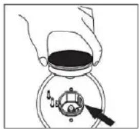
This appliance is factory fitted with Natural Gas Injectors (burner nozzles) and is also supplied with a ULPG conversion kit. To adapt the cooktop to a different type of gas, the gas injectors must be changed as follows:
- Remove the pan supports (trivets), burner caps and burner diffusers.
- Unscrew the injectors using a 7mm socket wrench.
- Replace the injectors with those supplied corresponding to the gas available (see burner and injector characteristics table)
IMPORTANT // On completing the operation, replace the old gas label with the one showing the new type of gas; the sticker is available in the User Manual package
natural_image
Illustration of hands holding a container with a lid and a dial indicator (no text or symbols)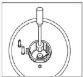
natural_image
Mechanical assembly diagram showing a central shaft and internal components (no text or labels)Adjusting the minimum flame intensity
The minimum flame intensity is adjusted at the factory. However, when the gas injectors are replaced or in special mains pressure
conditions, it may be necessary to readjust the intensity of the minimum flame.
Follow the operations below for each burner in order to adjust the minimum flame intensities:
- Light the burner.
- Turn the knob control anti-clockwise to the weakest flame.
- Remove the knob from the valve shaft (and gasket if there is one).
- Use a thin blade screwdriver to turn the bypass screw located on top of the gas valve shaft.
ULPG
Gently turn the bypass screw clockwise until it is completely tightened.
Natural Gas
Gently turn the bypass screw clockwise until it is completely tightened, then slowly turn it anti-clockwise for adjustment of the flame. The correct length of the flame is around 3 to 4mm.
- Put the knob back on and test if the flame goes out when quickly turning the knob control from the strongest flame to the weakest flame positions.
- For burners with flame failure device, make sure that the regulation obtained is sufficient to maintain the thermocouple activated when operating with the weakest flame. If it is not, increase the minimum flame intensity.
NOTE 11 A full operational test and atest for possible leakages must be carried out by the installer before leaving. Check all burner flames are blue in colour, stable and completely ignite at both high and low flame settings with no appreciable yellow tipping, carbon deposition, lifting, floating lighting back or objectionable odour. Test burners individually and in combination.
CONTACT DETAILS
AUSTRALIA
ARISIT PTY LIMITED
40-50 Mark Anthony Drive
Dandenong South, VIC 3175
Australia
P // 1300 762 219
Arisit.warranties@arisit.com
NEW ZEALAND
ARISIT PTY LIMITED
PO Box 68-140
Newton, Auckland 1145
New Zealand
P // 09 306 1020
F // 09 302 0077
sales@aristonappliances.co.nz
Tisira is committed to ongoing research and development. Every effort has been made to ensure all information in this service manual is correct at time of going to print. Dimensions should be used as a reference only and actual dimensions should be taken from the physical product only.
Manufacturer reserves the right to change specifications without notice.
tisira
- Content
- Warning & Safety Instructions
- Product Overview
- Operating Instruction
- Control knobs
- Lighting a burner
- Switching off
- Interruption to the electricity supply
- Regulating the flame
- Flame failure device
- Cleaning & Maintenance
- Cleaning the Burners
- Servicing the cooktop
- Installation
- Installation Accessories Supplied
- Installation Procedure
- Electrical Connection
- Gas Connection
- Natural gas 1.0 kPa ULPG 2.75 kPa
- Gas Conversion – Natural Gas / ULPG
- Adjusting the minimum flame intensity
- ULPG
- Natural Gas
- CONTACT DETAILS
- ARISIT PTY LIMITED
Brand : Tisira
Model : TGF64E
Category : Cooker