
IPAC14-LS - Air Conditioning Impecca - Free user manual and instructions
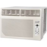
Find the device manual for free IPAC14-LS Impecca in PDF.


| Product Type | Portable Air Conditioner |
| Model | IPAC14-LS |
| Brand | Impecca |
| Cooling Capacity (Estimated) | 14,000 BTU |
| Power Supply | 115V, 60Hz (dedicated circuit recommended) |
| Current Draw (Estimated) | Approx. 12A |
| Operating Temperature Range | 62°F to 95°F (16°C to 35°C) |
| Modes | Auto, Cool, Dry, Fan (no heat on this model) |
| Fan Speeds | Auto, Low, Med, High |
| Timer Range | Up to 24 hours (Auto On/Off) |
| Sleep Mode | Yes (Economy mode) |
| Swing (Air Direction) | Yes (manual and auto swing) |
| Remote Control | Yes (with PMTS Follow Me feature) |
| Filter | Washable (3 filters: upper, lower A, lower B) |
| Water Drainage | Bottom drain plug (manual) and upper drain hose (continuous drain in dehumidify mode) |
| Exhaust Hose Length (Approx.) | Up to 5 ft (extendable, but should be kept short) |
| Window Kit Compatibility | Double-hung and horizontal slider windows (min. opening 26.5 inches) |
| Mobility | Casters and carrying handles |
| Dimensions (Estimated) | Approx. 17" x 15" x 30" (W x D x H) |
| Weight (Estimated) | Approx. 75 lbs |
| Safety | Ground fault current detection (plug test), auto restart, 3-min compressor delay |
| Error Codes | E1, E2, E3, E4, P1 (full tray) |
| Included Accessories | Remote with batteries, window kit (filler panels & foam seals), drain hose, exhaust hose & adapters |
Frequently Asked Questions - IPAC14-LS Impecca
User questions about IPAC14-LS Impecca
0 question about this device. Answer the ones you know or ask your own.
Ask a new question about this device
Download the instructions for your Air Conditioning in PDF format for free! Find your manual IPAC14-LS - Impecca and take your electronic device back in hand. On this page are published all the documents necessary for the use of your device. IPAC14-LS by Impecca.
USER MANUAL IPAC14-LS Impecca
natural_image
White portable air conditioner unit with gray handle and black base (no visible text or symbols)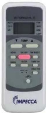
Portable Air Conditioner - User Manual
Model: IPAC14-LS
www.impecca.com
WARNING:
To avoid permanent damage to unit:
Ensure it is in the upright position for a MINIMUM of 6 hours and a RECOMMENDED time of 24 hours before powering on the first time.
ADVERTENCIA:
Spanish and French versions of this manual are available for download from www.impecca.com
Read the following notices and information carefully to ensure proper operation of your air conditioner unit.
This manual is solely provided for informational purposes and in no way constitutes a legally binding document between the manufacturer, distributor, and end consumer.
Important Safety Notices 4-5
Introduction
6
Getting to Know Your Air Conditioner 7
What's in the box and accessories 8
Installation Instructions 9
Water Drainage 10
Exhaust Hose and Window Filler Kit Installation 10-11
Operating Instructions 12
Unit Error Codes 17
Care & Maintenance 18
Troubleshooting
19
Customer Support 19
READ THESE NOTICES CAREFULLY—THEY ARE IMPORTANT!
WARNING
| Plug in power plug completely. | Do not start or stop the unit by inserting or pulling out the power plug. | Do not damage power cord or replace with a non-original power cord. |
| • Otherwise, it may cause electric shock or fire due to potential short circuit. | • It may cause electric shock or fire. | • It may cause electric shock or fire.• If the power cord is damaged, it must be replaced by the manufacturer or an authorized service center or a similarly qualified person to avoid hazard. |
| Do not modify power cord length. | Do not operate with wet hands or in a damp environment. | Do not direct airflow directly at room occupants. |
| • It may cause electric shock or fire. | • It may cause electric shock. | • This could be harmful to their health. |
| Always ensure effective grounding/earthing. | Do not allow water into or onto the front of cabinet, control panel or power cord. | Always use dedicated power outlet and circuit breaker. |
| • Incorrect or missing grounding may lead to electric shock. | • It may cause failure of unit or electric shock. | Sharing a circuit can lead to fire. |
| Unplug the unit if it emits strange sounds, smells or smoke. | Do not plug unit into an electrical socket that is loose or damaged. | Do not operate the unit while the chassis is open or removed. |
| • Unit may need repair. • It may cause fire and electric shock. | • It may cause electric shock. | |
| Ensure the power cord is kept away from any heating sources. | Do not disassemble or modify unit. | Do not use the power cord near flammable gas or combustibles, such as gasoline, benzene, paint thinner, etc. |
| • It may cause fire and electric shock. | • It may cause failure and electric shock. | • It may cause an explosion or fire. |
| Ventilate room before operating air conditioner if there was a gas leakage. | ||
| • It may cause explosion, fire, and burns. | ||
CAUTION
| When the air filter is removed for cleaning, avoid touching the internal metal parts of the unit. | Do not clean the air conditioner with water. | Ventilate the room well when used together with a stove, etc. |
| It may cause an personal injury and/or damage to the unit. | Water may enter the unit and degrade the insulation. It may cause an electric shock. | An oxygen shortage may occur when using a stove in a room with closed windows. |
| When the unit needs to be cleaned, power it off and unplug it. | Do not put a pet or house plant where it will be exposed to direct air flow. | Do not use for specialized purposes. |
| Do not clean unit when power is on as it may cause fire and electric shock and/or personal injury. | This could injure or be harmful to your pet or plants. | Do not use this air conditioner to preserve precision devices, food, pets, plants, and art objects.It may cause deterioration, etc. |

CAUTION
| Stop operation and remove window filler panels from window during severe storm or hurricane. | Hold the plug by the head of the power plug when unplugging unit. | Unplug the power cord when not using the unit for extended periods of time. |
| Operation during a severe storm may allow a significant amount of water to enter the indoors. | Pulling from the wire can cause wire to fray leading to electric shock or fire. | Will prevent damage to the unit. |
| Do not place obstacles around air-intake vents or inside cool air outlet. | Do not place heavy objects on the power cord and ensure that the cord is not pinched or stressed. | Always insert the filters securely. Clean filter at least once per month. |
| It may cause failure of appliance. There is danger of fire or electric shock. | Operation with dirty filters (or without filters) will effect performance and may cause damage to the unit. | |
| Do not use strong detergent such as wax or paint thinner to clean the unit. Use a damp, soft cloth. | ||
| Appearance may deteriorate due to change of product color or scratching of its surface. | ||
CAUTION
ELECTRICAL INFORMATION
- Be sure your electrical wiring is adequate for the model you have chosen. This information can be found on the rating label, a silver-colored sticker generally located on the upper-right side of the cabinet.
- Be sure the air conditioner is properly grounded. To minimize shock and fire hazards, proper grounding is
important. The power cord is equipped with a three-prong grounding plug for protection against shock hazards.
- Your air conditioner must be connected to a properly grounded wall receptacle. If the wall receptacle you intend to use is not adequately grounded or protected by a time
delay fuse or circuit breaker, have a qualified electrician install the proper receptacle.
- Ensure the receptacle is accessible after the unit installation.
NOTE: The power supply cord with this air conditioner contains a current detection device designed to reduce the risk of fire. In the event that the power supply cord is damaged, it cannot be repaired -- it must be replaced with a cord from the Product Manufacturer.
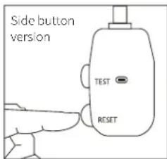
The power supply cord contains a current device that senses damage to the power cord and excess current draw from the unit. To test your current device do the following:
- Plug in the Air Conditioner.
- Press the TEST button. You will hear a click as the RESET button pops out within the rubber housing and the LED will turn off.
- Press the RESET button. You will hear a click as the button engages and the LED will illuminate.
- The power supply cord is now supplying electricity to the unit. Note: Your model may have the TEST and RESET buttons on the side or the front of the plug head.

NOTES:
- Do not use the TEST and RESET buttons to turn the unit on or off.
- If the current device fails the test or the power cord becomes damaged, the entire power cord must be replaced with an equivalent power cord and current device by a licensed electrician.
INTRODUCTION
Thank you for purchasing this quality Impecca portable air conditioner unit. To ensure the longest life and highest energy efficiency of your unit, please carefully follow these operating instructions. Keep these instructions in a safe place and consult them as needed. Please note that constant enhancement and improvements to our air conditioning units may mean that your model will slightly differ in appearance from the model pictured in this manual, but the actual operation and installation of the unit remains unchanged. This manual is solely provided for informational purposes and does not constitute a binding, legal contract.
SAFETY NOTICE:
This appliance should not be used by children or mentally/physically disabled persons without strict, direct supervision by a responsible adult. Never play with or around the appliance.
SAFETY INFORMATION
- Before operation, ensure your electrical installation (outlets and circuits) complies with the power specifications found on the unit.
- Before cleaning or maintaining the air conditioner, please turn off air conditioner and unplug the unit.
- Make sure the power cord isn't kinked, bent, or under the weight of sharp or heavy objects.
- Do not pull or yank the power cord to unplug the unit or move the air conditioner.
- Do not insert or unplug the power plug with wet hands.
- Only use a grounded power outlet. Make sure the grounding is functional.
- If the power cord is damaged, it must be replaced by the manufacturer or a qualified technician in order to avoid fire and electrical hazards.
- Should abnormal operation occur (such as a burning smell), please disconnect power cord immediately and contact your local dealer.
- If nobody is present to monitor the operation of the unit, please turn it off and disconnect the power cord.
- Do not splash or pour water on air conditioner to avoid causing a short circuit or damage to the unit.
- Do not put or hang dripping objects above the air conditioner.
- If using a drainage hose, ensure the ambient temperature remains well above freezing (32°F or 0°C) to avoid cracking or damaging the unit.
- Keep heat sources away from the air conditioner.
- Ensure the unit is far away from fire, inflammable, or explosive objects.
- Never allow children or persons with reduced physical, sensory, or mental capabilities to operate or play around the air conditioner without direct adult supervision.
- Never allow children to perform cleaning or other user-maintenance operations without direct adult supervision.
- Never attempt to repair or disassemble the air conditioner by yourself.
- Never insert objects into the air conditioner.
OPERATING CONDITIONS
- The air conditioner should only be operated within the temperature range of 62°F to 95°F (16°C to 35°C).
• The appliance is for indoor use only. - The appliance must be positioned so that the plug is accessible.
- A perimeter of 12"(30cm) around the air conditioner should be free of all objects.
- Do not operate the air conditioner in a humid environment.
- Please keep air inlet and air outlet clean and free of obstacles.
- During operation, close doors and windows to improve cooling effect.
- Please put the air conditioner on smooth and flat ground for operation to avoid noise and vibration.
- This air conditioner is equipped with casters that roll on smooth, flat surfaces.
- Do not tilt or turn over the air conditioner. If there's problem, please disconnect the power supply immediately and contact your local dealer or technical support.
- Avoid exposing the unit to direct sunlight.
GETTING TO KNOW YOUR AIR CONDITIONER


- Control Panel
- Horizontal directional blades
- Casters
- Carrying handle (both sides)
- Upper air intake
- Upper air filter (behind intake grille)
-
Air outlet (exhaust hose connection)
-
Dummy socket for power plug storage
- Power cord storage buckle
- Power cord connection
- Bottom tray drain outlet
- Lower air intake
- Lower air filter (behind intake grille)
- Upper Drain outlet
WHAT'S IN THE BOX:
Please verify your box for the following items. Note that some models may not include all items.
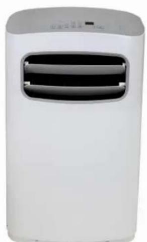
natural_image
White portable air conditioner unit with two ventilation slots (no visible text or symbols)1
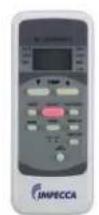
2
3
- Air Conditioning Unit
- Remote controller (may differ from photo)
- User's Guide
- Installation kit (see details below)
INSTALLATION ACCESSORY KIT ITEMS:
Illustrations may vary slightly from actual appearance of product.
| Diagram (not to scale) | Description Quantity | |
 | 1) Connector 2) Exhaust hose 3) Adapter “B”4) Security peg 5) Window filler panel kit | 1 set |
 | Foam Seals (2 adhesive, 1 non-adhesive) | 3 pieces |
 | Remote Controller and batteries | 1 set |
 | Drain hose | 1 piece |
Avoid damaging your new appliance! If required accessories are missing, please contact customer support.
INSTALLATION INSTRUCTIONS
Carefully review all of these instructions BEFORE proceeding to install and operate your air conditioner unit. Failure to do so may cause damage, injury, or bodily harm including permanent disability and/or death.
LOCATION:
- The air conditioner should be placed on a firm, level surface to minimize noise and vibration. For safe and secure positioning, place the unit on a smooth, level floor strong enough to support the unit.
- The unit has casters to aid in maneuverability, but it should only be rolled on smooth, flat surfaces. Use caution when rolling on carpeted surfaces. Do not attempt to roll the unit over objects.
- The unit must be placed within reach of a properly rated grounded socket.
- Never place any obstacles around the air inlet or outlet of the unit.
- Allow 1 to 3 feet (30cm to 100cm) of space from the wall with for efficient air-conditioning and prevent overheating.

EXHAUST HOSE INSTALLATION:
NOTE: For your unit to function properly, it is imperative that the exhaust hose be vented to the outside when used in Auto, Cooling and dehumidify modes.
-
Install the adapter onto the exhaust hose as shown in Figure B.
First completely expand about 5 inches of hose on both ends of the exhaust pipe. Insert and fasten the Adapter to the exhaust pipe by turning the it counter-clockwise at one end of the hose. Repeat the process at the opposite end of the hose with the Connector. -
Insert the connector of the now-assembled exhaust hose into the hole seat of the air outlet and slide the exhaust hose down along the arrow's direction as shown in Figure C. Pay attention to the tabs so that the connector clicks into place.
The exhaust hose can be compressed or extended moderately according to installation requirements, but it is preferable to shorten the hose to desired length.
IMPORTANT: DO NOT OVER-BEND OR KINK THE EXHAUST HOSE.
(Figure D)


natural_image
Pure diagram of a device with intersecting lines and shaded sections, no text or symbols presentCAUTION EXHAUST PORT
Make sure that there are no obstacles within 18" (50cm) around the exhaust outlet in order for the exhaust system to work properly.
Fig. D
WATER DRAINAGE
Certain functions of your air conditioning unit create condensation and the unit may need to evacuate accumulated water. Please carefully follow these instructions according to your operating and usage conditions.
COOLING MODE
During cooling mode, the unit attempts to evacuate all of the moisture through the exhaust hose to the outside along with the warm air exhaust. At times, when the humidity level is very high, excess water may collect in the bottom tray. If the water level of the bottom tray reaches a predetermined level, the unit beeps 8 times, the digital display area shows error P I. At this time the air conditioning/dehumidification process will immediately stop. However, the fan motor will continue to operate (this is normal).
Carefully move the unit to a drain location, remove the bottom drain plug and let the water drain away (see Figure E). Reinstall the bottom drain plug and restart the machine until the P I symbol disappears. If the error repeats, call for service.
NOTE: Be sure to reinstall the bottom drain plug before using the unit.

natural_image
Technical line drawing of a portable electronic device with ventilation grille and control panel (no text or symbols)Fig. E

DEHUMIDIFYING MODE ONLY: Remove the upper drain plug from the back of the unit and simply attach the drain hose to the hole. Place the open end of the hose adapter directly over the drain area in your floor or into another receptacle (see Figure F).
NOTE: Make sure the hose is secure so there are no leaks. Direct the hose toward the drain, making sure that there are no kinks that will stop water flow. Place the end of the hose into the drain and make sure the end of the hose is down to let the water flow smoothly (see Figure F). Do not lift up the hose as this may cause water to flow back into the unit.
WINDOW SLIDER KIT INSTALLATION
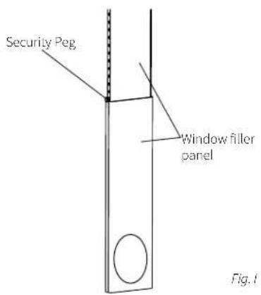
Your window slider kit has been designed to fit most standard double-hung and slider windows. However, it may be necessary for you to improvise/modify some aspects of the installation procedures for certain types of windows. Please refer to Figure G & Figure H for minimum and maximum window openings. The window slider kit can be fixed with an included security peg (see Figure I).


INSTALLATION IN A DOUBLE-HUNG SASH WINDOW:
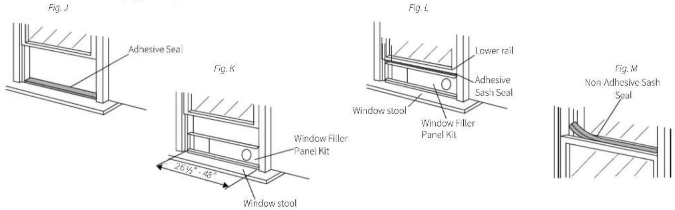
- Cut one adhesive foam seal to the proper length and attach it to the window stool. (Figure J)
- Attach the window filler panel kit to the window stool. Adjust the length of the window slider kit according to the width of window, shorten the adjustable window kit if the width of window is less than 26 ½ inches. Open the window sash and place the window slider kit on the window stool. (Figure K)
- Cut the other adhesive foam seal to the proper length and attach it to the bottom of the lower rail of the window.(Figure L)
- Close the window sash securely against the window filler panel kit.
- Cut the non-adhesive foam seal to an appropriate length and seal the open gap between the upper and lower windows. (Figure M)
INSTALLATION IN A HORIZONTAL SLIDER WINDOW:
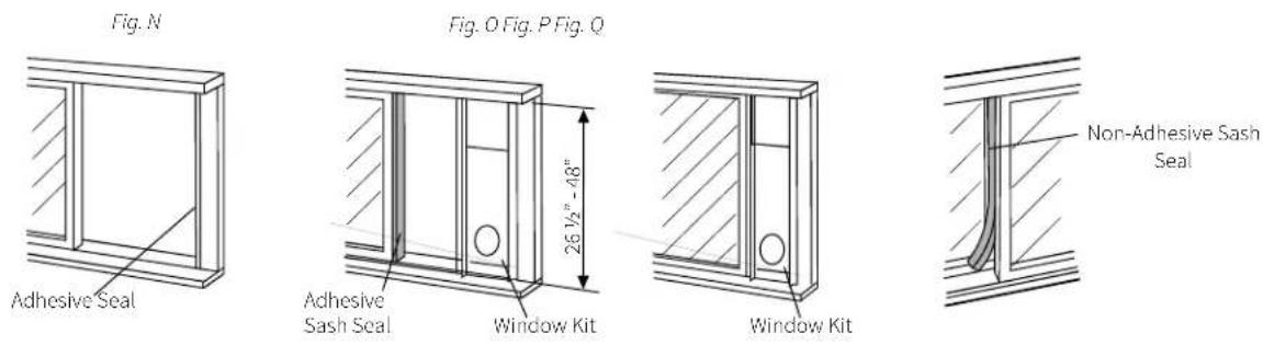
- Cut one adhesive foam seal to the proper length and attach it to the window frame. (Figure N)
- Attach the window filler panel kit to the window stool. Adjust the length of the window slider kit according to the height of window opening, shorten the adjustable window kit if the height of window is less than 26 ½ inches. Open the window sash and place the window slider kit on the window stool. (Figure O)
- Cut the other adhesive foam seal to the proper length and attach it on the part of the window sash that will come into contact with the filler panel kit. (Figure O)
- Close the sliding sash securely against the filler panel kit. (Figure P)
- Cut the foam seal to an appropriate length and sea the open gap between the top window sash and outer window sash. (Figure Q)
OPERATING INSTRUCTIONS
CONTROL PANEL AND REMOTE OVERVIEW
The following diagram and legend shows the functions of both the unit's control panel and the remote controller. Some functions are only available on select models.


1) ON/OFF BUTTON
Machine will start and stop when this button is pressed.
2) TEMPERATURE UP BUTTON
Push this button to increase the indoor temperature setting in 2°F increments to 88°F.
Push this button to decrease the indoor temperature setting in 2°F increments to 62°F.
4) MODE BUTTON
Each time the button is pressed, the operating mode of the air conditioning unit is selected in the following sequence: AUTO > COOL > DRY > HEAT* > FAN
5) FAN SPEED BUTTON
Adjust the machine fan speed from: AUTO > LOW > MED > HIGH
6) TIMER ON BUTTON (REMOTE\*)
Press this button to activate Auto-On. This feature turns on the unit at a programmed time within the next 24 hours.
Each press of the Timer-On button will increase the time setting in 30 minutes increments, up to 10 hours, then in 1 hour increments from 10 to 24 hours. To cancel the Auto-On time setting, just press the button until the time setting is 0.
7) TIMER OFF BUTTON (REMOTE\*)
Press this button to activate Auto-Off. This feature turns off the unit at a programmed time within the next 24 hours.
Each press of the Timer-Off button will increase the time setting in 30 minutes increments, up to 10 hours, then in 1 hour increments from 10 to 24 hours. To cancel the Auto-Off time setting, just press the button until the time setting is 0.
8) SLEEP (ECONOMY MODE) BUTTON
Select this function just before going to sleep. It maintains a comfortable temperature through the night and save energy. This function is available on COOL, HEAT* or AUTO modes only.
9) SWING BUTTON
Used to start and stop the function of the rotating directional and set the desired air flow direction.
10) DIGITAL DISPLAY
2-Digit LED display for the unit and LCD with additional indicators for the remote controller.
11) RESET BUTTON
Once the recessed RESET button is pressed, all of the current settings will be canceled and the controller will return to default settings. (A paper-clip or similar instrument is required.)
12) LOCK BUTTON
Lock the remote from accidental changes by pressing the lock button. Disable by pressing the button. (A paper-clip or similar instrument is required.)
13) LED DISPLAY BUTTON\*\*
Turns the temperature display on the unit on and off.
14) PMTS (FOLLOW ME) TEMPERATURE BUTTON
PMTS means Personal Mapping Temperature Sensor. This feature uses the remote controller to monitor temperature in another location of the room and sends information to the unit every 3 minutes.
*On the unit itself, the single "TIMER" button serves the function of both the "TIMER ON" and "TIMER OFF" buttons.
**NOT AVAILABLE ON ALL UNITS

MODE display
Displays the current selected mode. Including AUTO, COOL, DRY, HEAT* and FAN.
Transmission Indicator
This transmission indicator will show when remote controller transmits signals to the indoor unit.
Temp./Timer display
The temperature setting from 62^ F - 88^ F ( 17^ C - 30^ C), or timer setting (0-24h) will be displayed. If FAN mode is selected, there will be no display.
ON/OFF display
This indicator will be displayed when the unit is operating.
MODE display (FAN mode)
FAN SPEED display
Displays the selected fan speed: LOW, MED, HIGH. None of these three arrows display when the fan speed set to AUTO. The same is true when the unit mode is set to DRY or AUTO
FOLLOW ME (PMTS) display
When pressing FOLLOW ME/PMTS button in COOL or HEAT mode, the remote sensing function is activated and this indicator displays.
TIMER display
This display area shows the settings of the TIMER. That is, if only the Auto-on time function is set, it will display TIMER ON. If only the Auto-off time function is set, it will display TIMER OFF. If both functions are set, it will display TIMER ON OFF which indicates you have chosen both the Auto-on time and Auto-off time.
LOCK Indicator
LOCK display is displayed when pushing the LOCK button. Push the LOCK button to clear display.
*This feature is not used on this model
OPERATING INSTRUCTIONS (CONTINUED):
GENERAL NOTES:
Instructions are for both the remote controller and the unit control panel itself. When using the remote controller, it is possible and even recommended to select the operating mode before you press ON/OFF to start the unit. On the unit's control panel this is not possible and you must begin with the unit on.
AUTO MODE OPERATION:
Ensure the unit is plugged in and power is available. The indicator on the display panel of the indoor unit will illuminate.
- Press the MODE button to select AUTO.
- Press the TEMP UP or TEMP DOWN buttons to set the desired temperature. The temperature can be set within a range of 62^ to 88^ F in 2^ increments.
NOTES:
- In AUTO mode, the air conditioner will switch between cooling, fan, and dehumidifying modes by sensing the difference between the actual ambient room temperature and the set temperature on the remote controller.
- In AUTO mode, you cannot switch the fan speed. It is automatically controlled for maximum efficiency.
COOL/HEAT\*/FAN MODES OPERATION:
Ensure the unit is plugged in and power is available.
1. Press the MODE button to select COOL, HEAT* or FAN mode.
2. Press the TEMP UP or TEMP DOWN buttons to set the desired temperature. The temperature can be set within a range of 62^ to 88^ F in 2^ increments.
3. Press the FAN SPEED button to choose an appropriate fan speed: LOW, MED, HIGH, or AUTO..
NOTES:
- FAN mode simply circulates air and does not influence the room's ambient temperature. You cannot adjust the temperature in FAN mode.
- When in AUTO fan mode the remote controller LCD will not show any indicator for the fan speed.
FAN operation
- Press the “MODE” button until the “FAN” indicator light comes on.
- Press the “FAN SPEED” button to choose the fan speed. The temperature cannot be adjusted.
- There is no need to connect the exhaust hose to a window in fan mode.
Ensure the unit is plugged in and power is available.
1. Press the MODE button to select DRY mode.
2. Press the TEMP UP or TEMP DOWN buttons to set the desired temperature. The temperature can be set within a range of 62^ to 88^ F in 2^ increments.
NOTE: DRY mode controls fan speed automatically for effective dehumidification. This cannot be adjusted
DELAY START/STOP (TIMER) INSTRUCTIONS:
The timer buttons enable two separate functions: one to automatically start the unit within a 24 hour period of time and another to automatically turn off the unit within a 24 hour period of time. These functions are called, respectively, AUTO ON and AUTO OFF.
Note that the instructions below make reference to the TIMER ON and TIMER OFF buttons which are found on the remote controller. The procedure is the same for setting the delay from the unit's control panel except that there is just one button for both. Pressing the TIMER button once shows and sets the TIMER OFF function and pressing it twice shows and sets the TIMER ON function.
AUTO ON INSTRUCTIONS:
- Press the TIMER ON button. The remote controller shows TIMER ON, the last Auto-on setting time and the indicator "h" (indicating "hours") will be shown on the remote controller LCD. Now you are ready to reset the Auto-on time to START the operation.
- Push the TIMER ON button again to set desired Auto On time. Each time you press the TIMER ON button, the time will increase in 30 minutes increments, up to 10 hours, then in 1 hour increments up to 24 hours.
- After setting the TIMER ON, there will be a one-half second delay before the remote controller transmits the signal to the air conditioner. Then, after approximately another 2 seconds, the signal "h" will disappear and the set temperature will re-appear on the LCD display window.
AUTO OFF INSTRUCTIONS:
- Press the TIMER OFF button. The remote controller shows TIMER OFF, the last Auto-off setting time and the signal "h" will be shown on the LCD display area. Now it is ready to reset the Auto-off time to START the operation.
- Push the TIMER OFF button again to set desired Auto-off time. Each time you press the button, the time increases in 30 minutes increments, up to 10 hours, then at 1 hour increments up to 24 hours.
- After setting the TIMER OFF, there will be a one-half second delay before the remote controller transmits the signal to the air conditioner. Then, after approximately another 2 seconds, the signal "h" will disappear and the set temperature will re-appear on the LCD window.
EXAMPLES OF TIMERS:
AUTO ON: If you'd like your home or office to be cool after returning from an event or running errands, schedule the machine to turn on and cool the room for your arrival.
To set the machine to start in 6 hours, push the TIMER ON button. The display will read "h"; push the TIMER ON button until the display reads "5.0". Wait 3 seconds and the program will be activated once the LED resumes displaying the room temperature.
AUTO OFF: Your children rarely turn the air conditioning off during the day and you leave for work before they leave for school. Consider scheduling the unit to turn off automatically.
To set the machine to turn off in 1 hour, push the TIMER OFF button. The display will read "h"; push the
TIMER OFF button until the display reads "1.0". Wait 3 seconds and the program will be activated once the LED resumes displaying the room temperature.
COMBINED TIMERS: Save energy and money by programming your unit! You can use the Auto On and Auto Off functions simultaneously. An example of this feature is to turn off the unit in 1 hour when the kids leave for school and turn it on in 6 hours just before you return from work. (See above.)
SLEEP (Economy) operation
- Press this button, the selected temperature will increase (cooling) or decrease (heating) by 2^ / 1^ after 30 minutes. The temperature will then increase (cooling) or decrease (heating) by another 2^ / 1^ after an additional 30 minutes.
- The new temperature will be maintained for seven hours before it returns to the originally selected temperature, at which point Sleep mode ends and the unit will continue to operate as originally programmed.
- NOTE: This feature is unavailable under FAN or DRY mode.
PMTS (FOLLOW ME) Feature:
- NOTE: This feature can be activated from the remote controller ONLY. The remote controller acts as a remote thermostat allowing for the precise temperature control at its location.
- To activate the Follow Me/Temp Sensing feature, point the remote controller towards the unit and press the PMTS/Follow Me button. The remote displays the actual temperature at its location. The remote controller will send this signal to the air conditioner every three minutes interval until press the Follow Me/Temp Sensing button again.
- If the unit does not receive the PMTS signal during any seven-minute interval, the unit will beep to indicate the PMTS mode has ended.
SWING FUNCTION:
Use the SWING button to adjust the Up/Down airflow direction.
- One press of the button starts movement of directional airblade in 6° range, additional button presses will increase the range by 6° with each press. Keep pressing the button to move the directional airblade to the desired range.
NOTE: On some models the button only initiates Auto swing. - If keep pressing the SWING button without releasing for 2 more seconds, the auto swing feature of the directional airblade is activated. The airblade swings up/down automatically. Press it again to stop.
NOTE: If the unit senses that the blade positioning adversely affects room temperature settings, the
ADDITIONAL UNIT FEATURES
Auto Restart
- If the unit shuts off unexpectedly due to a power outage, it will restart with the previous function setting automatically when the power resumes.
- If you need full timer functionally you can hook up a properly-rated heavy duty timer to the unit to control on and off cycles. If doing so, it is imperative to avoid circumventing the third prong ground wire and having a timer that is rated accordingly to prevent risk of fire or electric shock.
Self Protection
• After the unit has stopped, it cannot restart operation for 3 minutes following shut down. This is to protect the unit. Operation will automatically resume after 3 minutes has elapsed.
HANDLING THE REMOTE CONTROL
Use the remote controller within a distance of 26 feet (8 meters) from the appliance, pointing it towards the receiver. Reception is confirmed by a beep.
CAUTION
- The air conditioner will not received signals from the remote controller if curtains, doors or other materials block the signals from the controller to the unit.
- Prevent any liquid from spilling onto or into the remote controller. Do not expose the remote controller to direct sunlight or heat.
- If the infrared signal receiver on the air conditioning unit is exposed to direct sunlight, the air conditioner may not function properly. Use curtains to prevent the sunlight from falling on the receiver.
REPLACING THE BATTERIES
The remote controller is powered by two AAA batteries housed in the rear part and protected by a cover.
To replace the batteries:
Step 1: Remove the cover by pressing and sliding off.
Step 2: Remove the old batteries and insert 2 new AAA batteries, placing the (+) and (-) ends correctly.
Step 3: Reattach the cover by sliding it back into position.
NOTE: When the batteries are removed, the remote controller erases all programming. After inserting new batteries, the remote controller must be reprogrammed.
If storing the unit for extended periods of time (such as the end of a season) remove the batteries from the remote controller to prevent corrosion.

natural_image
Line drawing of a portable air conditioner unit with wheels and vent slots (no text or symbols)

Use the following guidelines to understand and troubleshoot common error codes.
E I: Room temperature sensor error.
E2: Evaporator temperature sensor error
E3: Condenser temperature sensor error
E4: Display panel communication error
- For all of the above errors, unplug the unit and plug it back in.
P I: Bottom condensation tray is full
- Connect the drain hose and drain the collected water away.
- Note that frequent draining may be required, especially in humid climates and during seasonal weather changes.
- If protection repeats after draining, call for service.
CAUTION
ADDITIONAL REMOTE CONTROLLER INFORMATION
- Do not mix old and new batteries or batteries of a different type (e.g. alkaline and zinc).
- Do not leave the batteries in the remote controller if it is not going to be used for 2–3 months.
- Dispose of the old batteries in special battery disposal collection containers at sales sites or wherever local law states batteries may be disposed of.
REMOTE CONTROLLER SPECIFICATIONS
| Rated Voltage 3.0V (Dry batteries AAA x2) | |
| Lowest Voltage ofCPU Emitting Signal | 2.0 V |
| Signal Receiving Range 26 feet / 8m | |
| Environment ~41°F to 140°F (5°C to 60°C) | |
NOTE: All drawings in this manual are for illustrative purposes only. The actual shape and functions of your unit and remote controller may vary slightly.


Fig. S
IMPORTANT:
1) Be sure to unplug the unit before cleaning or servicing.
2) Do not use gasoline, thinner or other chemicals to clean the unit.
3) Do not wash the unit directly under a tap or using a hose. It may cause electrical danger.
4) If the power cord is damaged, it should be repaired by manufacturer or its agency.
AIR FILTER CLEANING:
Clean the air filter at least once every two weeks to prevent inferior fan operation because of dust.
REMOVAL: This unit has three filters. First remove the Upper filter. Then remove Lower filter A and then Lower filter B as shown in Figure R.
CLEANING: Wash the air filter by immersing it gently in warm water (about 104°F/40°C) with a neutral detergent. Rinse the filter and dry it in a shady place.
MOUNTING: Reinstall The upper filter, Lower filter B and then Lower filter A.
UNIT ENCLOSURE:
Use a lint-free cloth soaked with neutral detergent to clean the unit enclosure. Finish by wiping with a dry clean cloth.
BEFORE STORING OR NOT USING A UNIT FOR LONG PERIODS OF TIME:
Remove the rubber plug at the back of the unit and attach a hose to drain outlet. Place the open end of the hose directly over the drain area in your floor or receptacle. (See figure F on page 10.)
Remove the plug from the bottom drain outlet, all the water in the bottom tray will drain out. (See Figure E on page 10.)
Keep the appliance running on FAN mode for half a day in a warm room to dry the appliance inside and prevent mold from forming.
Stop the appliance and unplug it, wrapped the cord and bundle it with the tape (Figure S). Clean the air filter and reinstall it (see above). Remove batteries from the remote controller.
TROUBLESHOOTING TIPS:
| Problem Possible Causes | Remedies | |
| Unit does not start when pressing on/off button | P1 appears in the display window Drain the water in the bottom tray | |
| Room temperature is lower than the set temperature (cool mode) | Reset the temperature | |
| Room not cool enough | The windows or doors in the room are not closed | Make sure all the windows and doors are closed |
| There are heat sources inside the room | Remove the heat sources if possible | |
| Exhaust air duct is not connected or blocked | Connect the duct and make sure it can function properly | |
| Temperature setting is too high Decrease the set temperature | ||
| Air filter is blocked by dust Clean the air filter | ||
| Machine noisy or vibrates The ground is not level or not flat enough | Place the unit on a flat, level surface if possible | |
| Gurgling noises | The sound comes from the flowing of the refrigerant inside the air conditioner unit | This noise is normal |
| Power shuts off in heating mode | The automatic overheat protection function kicks in. When the temperature at the air outlet exceeds 158°F/70°C, the device will automatically shut off. | Switch on again after the unit has cooled off. |
CUSTOMER SUPPORT
For additional assistance, please visit our website or contact customer support.
Web: www.impecca.com
Phone: +1 866-954-4440

- Portable Air Conditioner - User Manual
- WARNING:
- To avoid permanent damage to unit:
- ADVERTENCIA:
- CAUTION
- ELECTRICAL INFORMATION
- NOTES:
- INTRODUCTION
- SAFETY NOTICE:
- SAFETY INFORMATION
- OPERATING CONDITIONS
- GETTING TO KNOW YOUR AIR CONDITIONER
- WHAT'S IN THE BOX:
- INSTALLATION ACCESSORY KIT ITEMS:
- INSTALLATION INSTRUCTIONS
- LOCATION:
- EXHAUST HOSE INSTALLATION:
- CAUTION EXHAUST PORT
- WATER DRAINAGE
- COOLING MODE
- WINDOW SLIDER KIT INSTALLATION
- INSTALLATION IN A DOUBLE-HUNG SASH WINDOW:
- INSTALLATION IN A HORIZONTAL SLIDER WINDOW:
- OPERATING INSTRUCTIONS
- CONTROL PANEL AND REMOTE OVERVIEW
- 1) ON/OFF BUTTON
- 2) TEMPERATURE UP BUTTON
- 4) MODE BUTTON
- 5) FAN SPEED BUTTON
- 6) TIMER ON BUTTON (REMOTE\*)
- 7) TIMER OFF BUTTON (REMOTE\*)
- 8) SLEEP (ECONOMY MODE) BUTTON
- 9) SWING BUTTON
- 10) DIGITAL DISPLAY
- 11) RESET BUTTON
- 12) LOCK BUTTON
- 13) LED DISPLAY BUTTON\*\*
- 14) PMTS (FOLLOW ME) TEMPERATURE BUTTON
- MODE display
- Transmission Indicator
- Temp./Timer display
- ON/OFF display
- MODE display (FAN mode)
- FAN SPEED display
- FOLLOW ME (PMTS) display
- TIMER display
- LOCK Indicator
- OPERATING INSTRUCTIONS (CONTINUED):
- GENERAL NOTES:
- AUTO MODE OPERATION:
- COOL/HEAT\*/FAN MODES OPERATION:
- FAN operation
- DELAY START/STOP (TIMER) INSTRUCTIONS:
- AUTO ON INSTRUCTIONS:
- AUTO OFF INSTRUCTIONS:
- EXAMPLES OF TIMERS:
- SLEEP (Economy) operation
- PMTS (FOLLOW ME) Feature:
- SWING FUNCTION:
- ADDITIONAL UNIT FEATURES
- Auto Restart
- Self Protection
- HANDLING THE REMOTE CONTROL
- REPLACING THE BATTERIES
- ADDITIONAL REMOTE CONTROLLER INFORMATION
- IMPORTANT:
- AIR FILTER CLEANING:
- UNIT ENCLOSURE:
- BEFORE STORING OR NOT USING A UNIT FOR LONG PERIODS OF TIME:
- CUSTOMER SUPPORT
Brand : Impecca
Model : IPAC14-LS
Category : Air Conditioning