
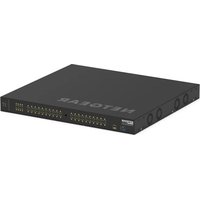
CNX-PAD8A - Network switch Crestron - Free user manual and instructions
Find the device manual for free CNX-PAD8A Crestron in PDF.


| Product Type | Network Switch |
| Brand | Crestron |
| Model | CNX-PAD8A |
| Number of Ports | 8 |
| Port Speed | 10/100/1000 Mbps |
| PoE Support | Yes, PoE+ (802.3at) |
| Form Factor | 1U Rackmount |
| Dimensions (W x H x D) | 19 x 1.72 x 8.5 inches (483 x 44 x 216 mm) |
| Weight | 5.5 lbs (2.5 kg) |
| Power Supply | Internal, 100-240V AC, 50/60Hz |
| Power Consumption | 30W (max) |
| Cooling | Fanless, silent operation |
| Management | Managed, with web interface and SNMP |
| VLAN Support | Yes, 802.1Q VLAN |
| Quality of Service (QoS) | Yes, 802.1p |
| Mounting | Rackmount ears included |
| Operating Temperature | 32°F to 104°F (0°C to 40°C) |
| Storage Temperature | -4°F to 158°F (-20°C to 70°C) |
| Humidity | 10% to 90% non-condensing |
| Certifications | FCC, CE, UL |
| Cleaning Instructions | Wipe with a dry, lint-free cloth. Do not use liquid cleaners. |
| Safety Precautions | Disconnect power before cleaning. Do not block ventilation. |
| Spare Parts / Repairability | Power supply and fan available from Crestron; professional repair required. |
| Additional Information | Refer to user manual for detailed configuration. |
Frequently Asked Questions - CNX-PAD8A Crestron
User questions about CNX-PAD8A Crestron
0 question about this device. Answer the ones you know or ask your own.
Ask a new question about this device
Download the instructions for your Network switch in PDF format for free! Find your manual CNX-PAD8A - Crestron and take your electronic device back in hand. On this page are published all the documents necessary for the use of your device. CNX-PAD8A by Crestron.
USER MANUAL CNX-PAD8A Crestron
Professional Audio Distribution Processor
Operations Guide
This document was prepared and written by the Technical Documentation department at:

CRESTRON®
Crestron Electronics, Inc.
15 Volvo Drive
Rockleigh, NJ 07647
1-888-CRESTRON
Contents
Professional Audio Distribution Processor: CNX-PAD8A 1
Description....1
Functional Description .... 1
Physical Description....1
Leading Specifications....6
Setup....7
Rack Mounting....7
Stacking....8
Hookup 9
Network Wiring....9
Identity Code....9
Programming 11
Programming with the Crestron AppBuilder....11
Programming with SIMPL Windows 12
CNX-PAD8A Example Programs....13
The CNX-PAD8A Basic Program....15
Problem Solving 20
Troubleshooting....20
Further Inquiries....21
Future Updates ....21
Return and Warranty Policies 22
Merchandise Returns / Repair Service 22
CRESTRON Limited Warranty....22
Professional Audio Distribution Processor: CNX-PAD8A
Description
Functional Description
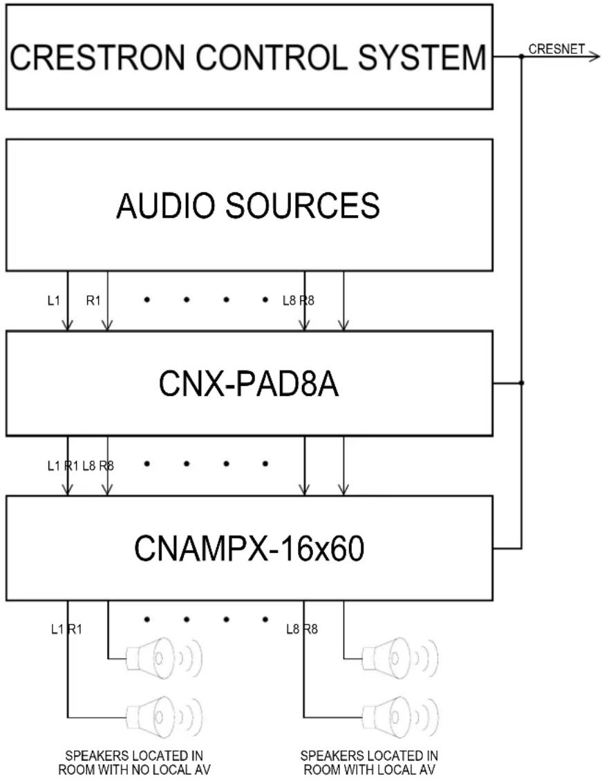
The Crestron Professional Audio Distribution Processor, CNX-PAD8A is an enhanced version of Crestron's professional high-end audio distribution system. It delivers audio from up to eight sources into as many as eight separate rooms and can be expanded with additional CNX-PAD8A chassis to 32 rooms (using the optional Audio Switcher Bussing Kit). Powered by a Crestron control system, the CNX-PAD8A can be programmed to select any available audio source, choose a room destination, and distribute a pre-amplified signal to as many as eight room amplifiers, each of which can be chosen according to its application. A general application of the CNX-PAD8A is shown on the next page. In addition, the CNX-PAD8A provides the mixing of stereo sources to mono. Any Crestron user interface – from keypad to touchpanel – provides access and control to the CNX-PAD8A's functions. The CNX-PAD8A should typically be installed with the Crestron amplifier (i.e., CNAMPX-16x60). The table after this paragraph provides a summary of the enhancements associated with the CNX-PAD8A.
CNX-PAD8A Functional Summary
CNX-PAD8A Professional Audio Distribution Processor
* Improved dynamic range
* Increased gain range
* Electronic mute increased to >-92 dB
* Signal to noise ratio improved to >-100 db at room outputs
* Crosstalk between channels has been reduced to >-92 dB
* Built in mono capability
General Application Scenario of the CNX-PAD8A
flowchart
graph TD
    A["CRESTRON CONTROL SYSTEM"] -->|L1 R1 L8 R8| B["CNX-PAD8A"]
    B -->|L1 R1 L8 R8| C["CNAMPX-16x60"]
    C -->|L1 R1 L8 R8| D["SPEAKERS LOCATED IN ROOM WITH NO LOCAL AV"]
    D --> E["SPEAKERS LOCATED IN ROOM WITH LOCAL AV"]
    F["CRESNET"] --> A
NOTE: Other applications are discussed in "Programming with the Crestron AppBuilder" on page 11.
Physical Description
The CNX-PAD8A is housed in a black enclosure with silk-screened labels on the front and rear panels. On the front of the unit there are 10 LEDs for indicating the unit's current status. There is also one LED on the back of the unit. All connections are made to the back of the unit. Refer to the physical view shown after these paragraphs.
Two mounting ears are provided for rack mounting and, for table-top mounting or stacking, four square rubber feet are provided. These feet are to be attached on the base of the unit for stability and to prevent slippage.
CNX-PAD8A Physical Views

other
| Component | Dimension (cm) | |-----------|----------------| | Total Width | 3.310 | | Total Height | 3.480 | | Top Diameter | 16.910 | | Top Height | 8.440 | | Top Height (Bottom) | 17.100 | | Top Height (Top) | 19.000 | | COX-PADIM Label | 3.469 | | COX-PADIM Label | 3.480 | | Reference Label | 8.407 | | Reference Label | 8.839 | | Reference Label | 42.951 | | Reference Label | 43.434 | | Reference Label | 48.260 | | Reference Label | 8.811 |CNX-PAD8A Ports
A number of ports are provided on the back of the CNX-PAD8A. Each has a silk-screened label. Refer to the illustration and descriptions below.
CNX-PAD8A Ports

NET
NOTE: There are no RJ-11 connectors on this product.
Use the supplied 4-pin network connector as described in "Network Wiring" on page 9 and connect the control system and other peripherals to this port.
(Chassis Ground)
Use this chassis screw to connect the audio source(s) common ground(s) to the CNX-PAD8A.
SOURCES 1 - 8
Each of the eight sets of four RCA connectors is used to connect the independent audio sources to the CNX-PAD8A. Of each set, two of the connectors are used for the left and right audio channels and the remaining two connectors are parallel stereo loop-throughs.
The eight rectangular blanks (labeled 1-2, 3-4, 5-6, and 7-8) are used with the optional Audio Switcher Bussing Kit. The kit contains a printed circuit board with eight connectors that when installed, is used to daisy-chain three additional CNX-PAD8As to provide up to a total of 32 room outputs. Refer to the latest revision of the CNX-ASBK Operations & Installation Guide (Doc. 8143) for further information.
ROOMS 1 - 8
These eight pair of RCA jacks output the pre-amplified audio to the corresponding room(s) amplifier(s). Each room output contains left and right audio channels.
CNX-PAD8A Indicators
There are 11 LED indicators primarily located on the front panel of the CNX-PAD8A (one of the 11 indicators is on the back panel). Each LED has a silk-screened label. Refer to the illustration and descriptions that follow.
CNX-PAD8A Indicators

PWR (Power)
This LED illuminates when 24 volts from the network is supplied to the CNX-PAD8A.
NET
This LED illuminates when communication between the control system and the CNX-PAD8A is established (the unit is polled on the network). Illumination indicates that the SIMPL Windows program currently loaded has a network device defined at the same NET ID as the CNX-PAD8A. The LED flashes when communication with the processor occurs.
ROOMS 1-8
These eight LEDs illuminate when the corresponding room is enabled to receive audio from the CNX-PAD8A.
SETUP
This LED is the lone indicator on the back panel. The purpose of the LED is intended for future use and was not defined at the time of printing.
CNX-PAD8A Pushbuttons
There is one pushbutton on the CNX-PAD8A (rear panel). The SETUP pushbutton is for future use and was not defined at the time of printing.
Leading Specifications
The three tables after this paragraph provide a summary of leading specifications for the CNX-PAD8A.
Leading Specifications of the CNX-PAD8A
| SPECIFICATION DETAILS | |
| Power Requirements | 24 VDC, 0.42 A, 10 W |
| Default NET ID | 44 |
| Crestron Application BuilderTM | Version 1.1 or later ^1 |
| SIMPLTM Windows® | Version 2.00.18 or later ^2 |
| 2-Series Control System Update ^3 | Version 1.000.CUZ or later ^4 |
| CNMSX-AV/PRO Update File | Version 5.12.57x.UPZ or later ^5 |
| CNRACKX/-DP Update File | Version 5.12.57w.UPZ or later ^5 |
| CEN/CN-TVAV Update File | Version 5.12.63v.UPZ or later ^5 |
| ST-CP Update File | Version 4.01.04s or later ^5 |
| Rack Space Required | 2U high, 1U wide |
| Environmental Temperature Range | 41° to 122°F (5° to 50°C) |
| Environmental Humidity | 10% to 90% RH (non-condensing) |
| Dimensions & Weight(without ears and feet) | Height: 3.47 in (8.81 cm)Width: 17.10 in (43.43 cm)Depth: 8.44 in (21.44 cm)Weight: 5.16 lb (2.34 kg) |
1 The product is supported in the Crestron Application Builder Software, both in the Residential and Commercial versions. Contact Crestron Customer Service for licensing details.
2 The latest software versions can be obtained from the What's New page (SIMPL Windows) or Downloads page (SIMPLWIN Library) of the Crestron website (www.crestron.com). New users are required to register in order to obtain access to the FTP site. For programming purposes, the CNX-PAD8A is completely substitutable for the CNX-PAD8.
3 Crestron 2-Series control systems include the AV2, AV2 with Card Cage, CP2, CP2E, PAC2, PAC2M, PRO2, and RACK2.
4 Filenames for 2-Series control system update files have a CUZ extension and can be obtained from the What's New page (Control Systems Update Files section) or Downloads page (OPSYS Library) of the Crestron website.
5 CNX upgrade files are required for either CNMSX-AV/Pro or CNRACKX/-DP. Filenames for CNX upgrade files have a UPZ extension and ST-CP files are in one EXE or zipped UPZ file. All can be obtained from the What's New page (Control Systems Update Files section) or Downloads page (OPSYS Library) of the Crestron website (www.crestron.com). Update files are specifically designed for certain control systems. If an update file is loaded into a control system other than the device for which it was intended, it may lockup the control system, which would then have to be returned to Crestron. Update files with an "S" designator are for the ST-CP, "V" designator for CEN/CN-TVAV, "W" for CNRACKX-DP, and "X" for CNMSX-AV/Pro control systems. Control systems are able to recognize and reject incorrect update files. However, when updating control systems, do not ignore Crestron Viewport warning prompts or messages.
Preamp Specifications of the CNX-PAD8A (Per Channel)
| SPECIFICATION DETAILS | |
| Input Impedance | 54K Ohms |
| Output Impedance | 37.5 Ohms |
| Total Harmonic Distortion (THD) | < 0.02% |
| S/N Ratio | >-100 dB |
| Maximum Input Level (Flat Mode) 3.2 RMS | |
| Maximum Output Level 2.5 RMS | |
| Crosstalk > -92 dB | |
| Gain Range (Excluding Mute) -80 dB to +20 dB | |
| Volume Steps 1 dB | |
| Mute >-92 dB (electronic mute) | -79 dB (minimum volume) |
NOTE: A chassis ground screw is provided in the back of the unit to connect the CNX-PAD8A to the audio source common ground(s).
Tone Specifications of the CNX-PAD8A (Per Channel)
| SPECIFICATION DETAILS | |
| Frequency Response (10 Hz to 20 KHz) | +/- 0.2 dB |
| Bass Gain Range (100 Hz) | +/- 12 dB |
| Bass Step Size (100 Hz) | 2 dB steps |
| Treble Gain Range (10 KHz) +/- 12 dB | |
| Treble Step Size (10 KHz) 2 dB steps |
As of the date of manufacture, the CNX-PAD8A has been tested and found to comply with specifications for CE marking.

NOTE: This device complies with part 15 of the FCC rules. Operation is subject to the following two conditions: (1) these devices may not cause harmful interference, and (2) these devices must accept any interference received, including interference that may cause undesired operation.
Setup
Rack Mounting
WARNING: To prevent bodily injury when mounting or servicing this unit in a rack, take special precautions to ensure that the system remains stable. The following guidelines are provided to ensure your safety:
- When mounting this unit in a partially filled rack, load the rack from the bottom to the top with the heaviest component at the bottom of the rack.
- If the rack is provided with stabilizing devices, install the stabilizers before mounting or servicing the units in the rack.
NOTE: If rack mounting is not required, rubber feet are provided for tabletop mounting or stacking. Apply the feet near the corner edges on the underside of the unit. Refer to "Stacking" on page 8 for details.
NOTE: Reliable grounding of rack mounted equipment should be maintained. Particular attention should be given to supply connections other than direct connections to the branch circuit. (e.g., use of power strips).
Two “ears” are provided with the CNX-PAD8A so that the unit can be rack mounted. These ears must be installed prior to mounting. Complete the procedure after this paragraph to attach ears to CNX-PAD8A. The only tool required for this procedure is a #2 Phillips screwdriver.
-
There are 16 screws (four #6-32 x 0.25" LG and 12 #6-32 x 0.375" LG) that secure the CNX-PAD8A top cover. Remove the three screws closest to the front panel from one side of the unit.
-
Position a rack ear so that its drilled holes align with the holes vacated by the screws in step 1.
-
Secure the ear to the CNX-PAD8A with three screws from step 1, as shown below.
Ear Attachment for Rack Mounting

-
Repeat procedure (steps 1 through 3) to attach ear to other (right) side.
-
If the rear panel of the CNX-PAD8A is accessible when mounted in the rack, install the CNX-PAD8A. If the rear panel is NOT accessible, perform the hookup procedure before rack installation.
Stacking
Four "feet" are provided with the CNX-PAD8A so that if the unit is not rack mounted, the rubber feet can provide stability when placed on a flat surface or stacked. These feet should be attached prior to the hookup procedure. Refer to the illustration below for placement of the feet.
Feet Location (Bottom View of Unit)

Hookup
Refer to the hookup diagram after this paragraph. Other than making the power connection last, complete the connections in any order. RCA cables are not supplied.
NOTE: Refer to "Network Wiring" on page 9 when making connections to the port labeled NET.
Hookup Connections for the CNX-PAD8A

* REFER TO NOTE AFTER THIS ILLUSTRATION.
NOTE: Each CNX-PAD8A is capable of distributing audio to eight rooms, maximum. It is possible to expand distribution to more rooms, if additional CNX-PAD8As are introduced into the system. Crestron recommends a maximum of four CNX-PAD8As per system. Therefore, audio can be distributed to a maximum of 32 rooms. Each input source has two sets (left and right) of RCA jacks connected in parallel. Use one set of the jacks for source input and the other set for loop-through.
Network Wiring
NOTE: When making wire connections, refer to the latest revision of the Cresnet Network Interconnect Drawing (Doc. 5411). The document can be obtained from the Downloads page (CABLES and MANUAL Libraries) of the Crestron website (www.crestron.com). Search for the CRESNET.PDF files.
When calculating the wire gauge for a particular network run, the length of the run and the power factor of each network unit to be connected must be taken into consideration. If network units are to be daisy-chained on the run, the power factor of each network unit to be daisy-chained must be added together to determine the power factor of the entire chain. The length of the run in feet and the power factor of the run should be used in the following resistance equation to calculate the value on the right side of the equation.
Resistance Equation
$$ R < \frac {4 0 , 0 0 0}{L \times P F} $$
Where: R = Resistance (refer to table below).
L = Length of run (or chain) in feet.
PF = Power factor of entire run (or chain).
The required wire gauge should be chosen such that the resistance value is less than the value calculated in the resistance equation. Refer to the table after this paragraph.
Wire Gauge Values
| RESISTANCE (R) WIRE GAUGE | |
| 4 | 16 |
| 6 | 18 |
| 10 | 20 |
| 15 | 22 |
| 13 | Doubled CAT5 |
| 8.7 | Tripled CAT5 |
NOTE: All network wiring must consist of two twisted-pairs. One twisted pair is the +24V conductor and the GND conductor and the other twisted pair is the Y conductor and the Z conductor.
NOTE: When daisy chaining network units, always twist the ends of the incoming wire and outgoing wire which share a pin on the network connector. After twisting the ends, tin the twisted connection with solder. Apply solder only to the ends of the twisted wires. Avoid tinning too far up or the tinned end becomes brittle and breaks. After tinning the twisted ends, insert the tinned connection into the network connector and tighten the retaining screw. Repeat the procedure for the other three network conductors.
Identity Code
Every equipment and user interface within the network requires a unique identity code (NET ID). These codes are recognized by a two-digit hexadecimal number from 03 to FE. The NET ID of the unit must match an ID code specified in the SIMPL Windows program. The NET ID of each CNX-PAD8A has been factory set to 44. The NET IDs of multiple CNX-PAD8As in the same system must be unique and changed from a personal computer (PC) via VisionTools® Pro-e (herein known as VT Pro-e) or SIMPL Windows.
NOTE: VT Pro-e is a Windows compatible software package for creating Crestron touchpanel screen designs.
The method for changing the unit's NET ID is identical regardless of the software chosen. Complete the following steps to change the NET ID.
- Attach only one of the CNX-PAD8As to the control system (verify that the software is running).
-
From the SIMPL Windows or VT Pro-e menu, select Tools | Viewport to open the Crestron Viewport.
-
From the Viewport menu, select Functions | Set Network ID. The software checks the baud rate and then opens the "Set Network ID" window.
- In the "Set Network ID" window, select the CNX-PAD8A from the Current Network Devices text window.
- From the Choose the new network ID for the selected device (Hex): text box, select the new NET ID for the CNX-PAD8A.
- Click Set ID to initiate the change. This will display the "ID command has been sent" window.
- In the "Command Complete" window, click OK.
- In the Current Network Devices text window, verify the new NET ID code.
- In the "Set Network ID" window, click Close.
NOTE: The new NET ID code may also be verified by selecting Diagnostic | Report Network Devices in the Viewport.
- Repeat this procedure for each CNX-PAD8A to be added to the network.
Programming
The CNX-PAD8A can be programmed using various Crestron tools: Crestron Application Builder ^™ (herein know as the AppBuilder) and SIMPL Windows. Each tool requires that the user have an unequal degree of programming knowledge. The flexibility of each tool is proportional to the degree of programming expertise (i.e., the more flexible, the more a programmer needs to know and account for). Of course, one can initiate programming using the easiest method (Crestron AppBuilder) and use advance techniques that are available from SIMPL Windows to customize the job.
Easiest method of programming that by itself does not offer the greatest amount of flexibility.
Programming with the Crestron AppBuilder
The Crestron AppBuilder offers automatic programming for such residential and commercial applications as audio distribution, home theater, video conferencing, and lighting. The interface of this tool guides you through a few basic steps for designating rooms and specifying the control system, touchpanels, devices, and functionality. Crestron AppBuilder room audio configurations that utilize the CNX-PAD8A may include such scenarios as “Control/Amplification at head-end, at room, via local display device, or via 3 ^rd party surround sound processor/receiver.” The Crestron AppBuilder then programs the system, including all touchpanel projects and control system logic.
The figure on the next page shows simplified block diagrams of typical room audio configurations utilizing the CNX-PAD8A.
Typical Room Audio Configurations for the CNX-PAD8A

flowchart
graph LR
    A["Control System"] --> B["Head-end Sources"]
    B --> C["CNX-PAD8A"]
    C --> D["L"]
    C --> E["R"]
    D --> F["CNAMPX 16x60"]
    E --> F
    F --> G["Room"]
    G --> H["8 ZONE Speaker-Level Audio"]
    G --> I["R"]
    I --> J["Local Source(s)"]

    K["Control System"] --> L["Head-end Sources"]
    L --> M["CNX-PAD8A"]
    M --> N["L"]
    M --> O["R"]
    N --> P["CNAMPX 16x60"]
    O --> P
    P --> Q["Room"]
    Q --> R["8 ZONE Speaker-Level Audio"]
    Q --> S["R"]
    S --> T["Local Source(s)"]

    style A fill:#f9f,stroke:#333
    style K fill:#f9f,stroke:#333
    style L fill:#f9f,stroke:#333
    style M fill:#f9f,stroke:#333
    style N fill:#f9f,stroke:#333
    style P fill:#f9f,stroke:#333
    style Q fill:#f9f,stroke:#333
    style R fill:#f9f,stroke:#333
The Crestron AppBuilder is fully integrated with Crestron's suite of software development tools, including SIMPL Windows, VT Pro-e, Crestron Database, User IR Database, and User Modules Directory. The Crestron AppBuilder accesses these tools behind the scenes, enabling you to easily create robust systems.
Programming with SIMPL Windows
SIMPL (Symbol Intensive Master Programming Language) is an easy-to-use programming language that is completely integrated and compatible with all Crestron system hardware. The objects that are used in SIMPL are called symbols. SIMPL Windows offers drag and drop functionality in a familiar Windows ^® environment.
SIMPL Windows is Crestron's software for programming Crestron control systems. It provides a well-designed graphical environment with a number of workspaces (i.e., windows) in which a programmer can select, configure, program, test, and monitor a Crestron control system.
The next three sections describe a CNX-PAD8A within SIMPL Windows. The first section provides initial configuration information, the second section identifies the CNX-PAD8 symbol and defines its inputs and outputs, and the final section discusses an example program.
NOTE: The following descriptions assume that the reader has knowledge of SIMPL Windows. If not, refer to the extensive help information provided with the software.
NOTE: Keep in mind that the CNX-PAD8A does not ship with default parameters (i.e., bass, balance). Therefore, these parameters must be made on the CNX-PAD8A symbol, which is set in SIMPL Windows.
Configure CNX-PAD8A Program
To create a program with a CNX-PAD8A, refer to the table below for initial configuration information.
Configure CNX-PAD8A Program
| DEVICE SYLIBRARY R | SYMBOL DROPEQUIRED WH | ADDITIONALERE SETUP | |
| Control Systems | Desired control system | System Views | Refer to the documentation supplied with the specific control system for additional setup information. |
| Cresnet Control Modules / Cresnet Audio Modules | CNX-PAD8A System | System Views, Cresnet Units | CHANGE NET ID (OPTIONAL) - Double-click on CNX-PAD8A to open the "Device Settings" window. Select the NET ID tab and scroll to the desired hexadecimal ID. (Alternatively, single-click then right click on CNX-PAD8A and select Configure to open "Device Settings" window.) |
SIMPL is Crestron's object-oriented programming language designated for easy implementation of the control system requirements. The objects that are used in SIMPL are called symbols.
CNX-PAD8A Symbol
The CNX-PAD8A symbol is defined by the inputs assigned to its ports. The diagram in this section shows the symbol associated with the ports of the CNX-PAD8A in SIMPL Windows. Because the inputs to the symbol are numerous, a table follows the diagram to list the functional descriptions.
Detail View of CNX-PAD8A Symbol (ID44) in SIMPL Windows Programming Manager

flowchart
graph TD
    A["ROOM_1_VOL_MUTE-FB"] --> B["mute1"]
    C["ROOM_8_VOL_MUTE-FB"] --> D["mute8"]
    E["ROOM_1-ON"] --> F["room-1-on"]
    G["ROOM_8-ON"] --> H["room-8-on"]
    I["ROOM_1_LOUDNESS-ON"] --> J["loudness1"]
    K["ROOM_8_LOUDNESS-ON"] --> L["loudness8"]
    M["ROOM_1_MONO-ON"] --> N["mono-mode-1"]
CNX-PAD8ASymbol Input Signal Functional Descriptions
| INPUT TYPE NAME / RANGE A / D* DESCRIPTION | ||
| through | D The mute inputs electronically cut sound to a room for as long asremains high. | |
| through | D When any of these inputs go high, the signals close relays enabling audio to the corresponding rooms. When an input goes low, the corresponding relay opens and cuts audio to the room (mechanical mute). | |
| through | D This input activates the loudness function commonly available on stereo amplifiers. | |
| through | D Ainput will change the room's audio setting from stereo to mono. Both left and right outputs carry the same signal. | |
| through | A Selects the audio source for the room.1 | |
| through | A Controls the audio level for each room. | |
| through | A This input specifies a level for the setting.2 | |
| through | A This input specifies a level for the setting.2 | |
| through | A This input specifies a level for the setting.2 | |
| through | A This input represents a scaling factor.3 | |
| through | A This input represents a scaling factor.3 | |
| through | A This input represents source gain compensation.4 | |
* Analog or Digital
-
The
analogs select the audio source for the specified room. For example, to distribute audio from input 3 to room 2, must be set to 3 (typically via an Analog Initialize symbol). If equals 0, then no audio will be sent. -
These inputs specify levels for the settings relative to the 50% mark. That is, a
input with a value of 50% indicates that audio is distributed evenly between the left and right speakers. Likewise, 50% indicates a neutral level for treble and bass. -
These inputs are scaling factors. That is, if
equals 20% and the corresponding equals 80%, then the distributed output will be scaled accordingly -
The
inputs are measured relative to 50%. These signals represent source gain compensations that allow for normalization of audio levels for different sources. For example, the volume range of a VCR can be made equal to that of a CD player.
CNX-PAD8A Example Programs
The CNX-PAD8A can be programmed to fit any customized installation. SIMPL Windows programs are available to provide basic functions, extended functions, and individual room control with optional keypanels (CN-WP12FI, etc.). The available CNXPAD8A.SMW program described in the subsequent subsections provides basic control of the CNX-PAD8A. By using a touchpanel, one of eight audio sources may be selected, distributed to room amplifiers, and the volume may be adjusted.
A more complete sample program is available in file CNXPAD8A.ZIP. This package includes the basic program with additional control of the tone, balance, and maximum/minimum volume for each room output, as well as input compensation for each source. The software includes a SIMPL Windows program and VisionTools Pro files to customize touchpanel displays.
NOTE: There is no need to recreate these sample SIMPL Windows programs. Both programs are available from the Downloads page (Examples Library) of the Crestron website (www.crestron.com). Search for CNXPAD8A.SMW or the CNXPAD8A.ZIP. These files contain the necessary files to recreate the following programming sample.
NOTE: VisionTools Pro (VT Pro) is a Windows® compatible software package for creating Crestron touchpanel screen designs.
The CNX-PAD8A Basic Program
The CNX-PAD8A basic SIMPL Windows program is described below in block diagrams. The diagrams show the symbols that are required to perform the audio distribution functions. There may be up to 32 room outputs of a daisy-chained CNX-PAD8A system but, for clarity, only one is described.
The touchpanel or other user interface must be programmed with eight source select signals and a room off signal (A), volume up and volume down signals (B), and a mute signal (C). The signals are sent to the basic symbols that are discussed in this section. The touchpanel also has to be programmed to receive and utilize button indicator illuminate signals (D).
Detail View of Digital Signals for a Touchpanel (ID-03) in SIMPL Windows' Programming Manager

flowchart
graph TD
    A["Room 1_source_1_sel"] --> B["fb1"]
    A --> C["fb2"]
    A --> D["fb3"]
    A --> E["fb4"]
    A --> F["fb5"]
    A --> G["fb6"]
    A --> H["fb7"]
    A --> I["fb8"]
    A --> J["fb9"]
    A --> K["fb10"]
    A --> L["fb11"]
    A --> M["fb12"]
    N["Room 1_source_1_sel"] --> O["press1"]
    P["Room 1_source_2_sel"] --> Q["press2"]
    R["Room 1_source_3_sel"] --> S["press3"]
    T["Room 1_source_4_sel"] --> U["press4"]
    V["Room 1_source_5_sel"] --> W["press5"]
    X["Room 1_source_6_sel"] --> Y["press6"]
    Z["Room 1_source_7_sel"] --> AA["press7"]
    AB["Room 1_source_8_sel"] --> AC["press8"]
    AD["Room 1_off_sel"] --> AE["press9"]
    AF["Room 1_volume_up"] --> AG["press10"]
    AH["Room 1_volume_down"] --> AI["press11"]
    AJ["Room 1_mute"] --> AK["press12"]
Interlock symbol S-3 receives the source selection signals (A) from the touchpanel. The selected signal is retained and the interlock sends the appropriate feedback signal (D) to the touchpanel to illuminate the corresponding button indicator.
Detail View of Interlock Symbol (S-3) in SIMPL Windows' Programming Manager

flowchart
graph TD
    A["room_1_source_1"] --> B["i1"]
    C["room_1_source_2"] --> D["i2"]
    E["room_1_source_3"] --> F["i3"]
    G["room_1_source_4"] --> H["i4"]
    I["room_1_source_5"] --> J["i5"]
    K["room_1_source_6"] --> L["i6"]
    M["room_1_source_7"] --> N["i7"]
    O["room_1_source_8"] --> P["i8"]
    Q["room_1_off"] --> R["i9"]
    B --> S["Interlock"]
    D --> S
    F --> S
    H --> S
    J --> S
    L --> S
    N --> S
    P --> S
    R --> S
    S --> T["room_1_source_1_sel"]
    S --> U["room_1_source_2_sel"]
    S --> V["room_1_source_3_sel"]
    S --> W["room_1_source_4_sel"]
    S --> X["room_1_source_5_sel"]
    S --> Y["room_1_source_6_sel"]
    S --> Z["room_1_source_7_sel"]
    S --> AA["room_1_source_8_sel"]
    S --> AB["room_1_off_sel"]
Analog initialize symbol S-2 receives the source select signal from the touchpanel (A) and outputs analog signal room_1_source. This signal is routed to the CNX-PAD8A (E) and the symbols that are used to illuminate the front panel LED (F). A room_1_off signal from the touchpanel turns the source selection signal off.
Detail View of Analog Initialize Module (S-2) in SIMPL Windows' Programming Manager

flowchart
graph LR
    A["room_1_source_1"] --> B["Analog Initialize"]
    C["room_1_source_2"] --> B
    D["room_1_source_3"] --> B
    E["room_1_source_4"] --> B
    F["room_1_source_5"] --> B
    G["room_1_source_6"] --> B
    H["room_1_source_7"] --> B
    I["room_1_source_8"] --> B
    J["room_1_off"] --> B
    B --> K["room_1_source"]
    K --> L["E"]
    K --> M["F"]
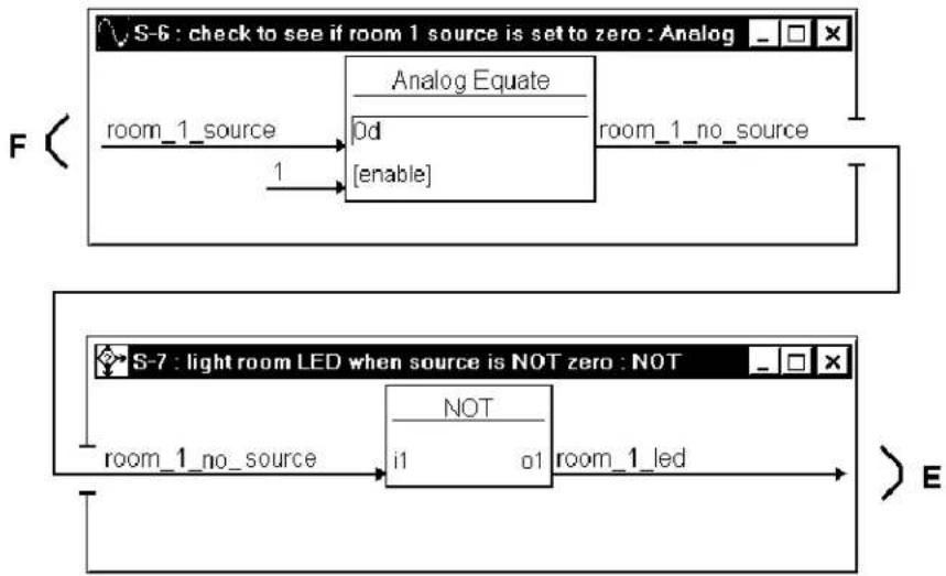
Symbols S-6 and S-7 illuminate the CNX-PAD8 front panel LED for the corresponding room that is enabled to receive audio. The room audio source selection signal (F), from the S-2, causes S-6 to signal S-7 that a source is selected by room 1. NOT symbol S-7 sends the signal to illuminate the front panel LED (E).
Detail View of Analog Equate and NOT Symbols (S-6 and S-7) in SIMPL Windows' Programming Manager
flowchart
graph TD
    A["S-6: check to see if room 1 source is set to zero : Analog"] --> B["Analog Equate"]
    B --> C["0d"]
    B --> D["enable"]
    E["S-7: light room LED when source is NOT zero : NOT"] --> F["NOT"]
    F --> G["i1"]
    F --> H["o1"]
    G --> I["room_1 Led"]
    H --> I
    I --> J["E"]
An analog ramp is used to adjust the room volume. The symbol receives volume_up and volume_down signals (B) from the touchpanel buttons. The level of the volume is sent to the CNX-PAD8A (E). The ramp will adjust through the entire range of the volume (0% to 100%) in 5-seconds.
Detail View of Analog Ramp Symbol (S-1) in SIMPL Windows' Programming Manager

flowchart
graph LR
    A["room_1_volume_up"] --> B["Analog Ramp"]
    C["room_1_volume_down"] --> B
    B --> D["up"]
    B --> E["out"]
    B --> F["down"]
    B --> G["[mute"]]
    B --> H["Time 5s"]
    D --> I["room_1_volume"]
    E --> I
    F --> I
    G --> I
    H --> I
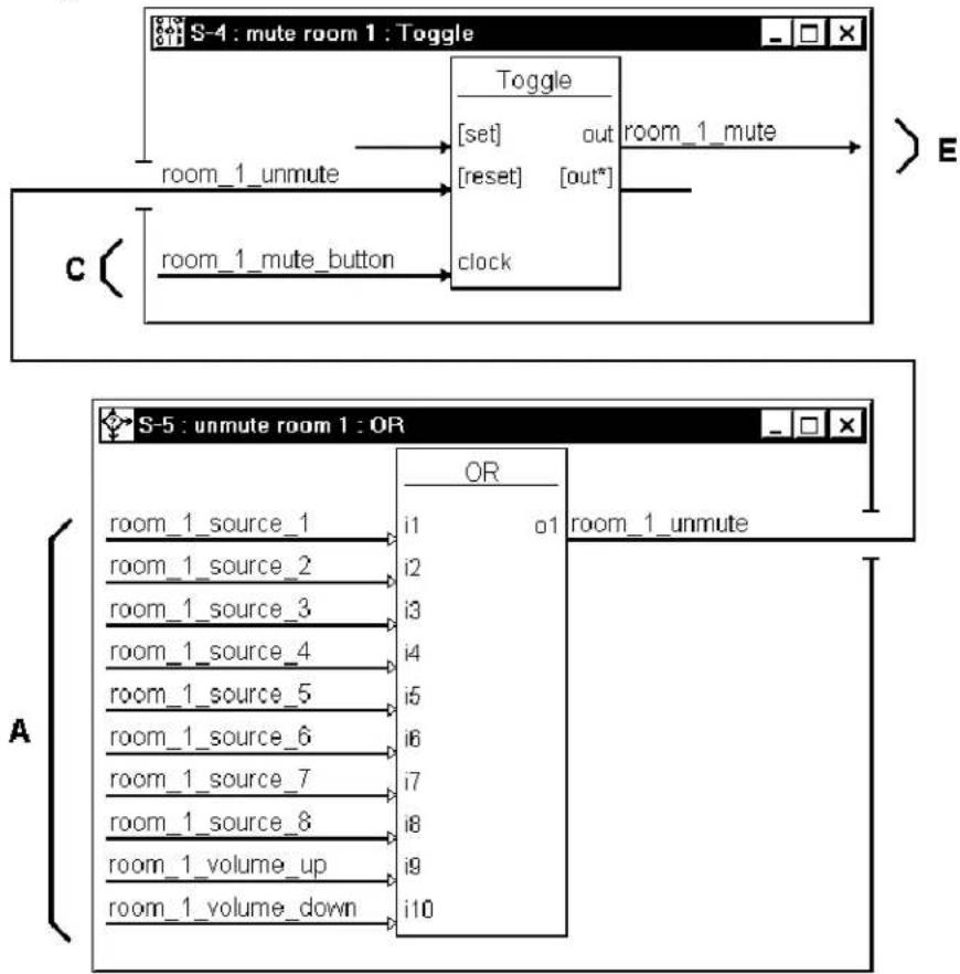
The next two symbols (S-4 and S-5) control the mute function of the CNX-PAD8A. While the room is receiving audio, pressing the MUTE button of the touchpanel (C) clocks the toggle S-4 to output the room_1_mute signal from the high output. This signal is sent to the CNX-PAD8A (E) to mute the audio. When in the “mute mode”, pressing the touchpanel MUTE button again clocks the toggle to remove the mute signal.
While in the “mute mode”, pressing any source or volume button of the touchpanel (A) is also input to the OR symbol S-5. The output of this symbol resets toggle S-4 to remove the mute signal (E) from the CNX-PAD8A.
Detail View of Toggle and OR Symbols (S-4 and S-5) in SIMPL Windows' Programming Manager
flowchart
graph TD
    subgraph S-4: Toggle
        A["Room 1_unmute"] --> B["Reset"]
        C["Room 1_mute_button"] --> D["Clock"]
        E["Room 1_mute"] --> F["set"]
        G["out"] --> H["out"]
        I["out*"] --> J["out"]
    end
    subgraph S-5: OR
        K["Room 1_source_1"] --> L["i1"]
        M["Room 1_source_2"] --> N["i2"]
        O["Room 1_source_3"] --> P["i3"]
        Q["Room 1_source_4"] --> R["i4"]
        S["Room 1_source_5"] --> T["i5"]
        U["Room 1_source_6"] --> V["i6"]
        W["Room 1_source_7"] --> X["i7"]
        Y["Room 1_source_8"] --> Z["i8"]
        AA["Room 1_volume_up"] --> AB["i9"]
        AC["Room 1_volume_down"] --> AD["i10"]
    end
With additional programming, the CNX-PAD8A can adjust settings for each room. In the basic program, these extended capabilities are factory set to values that are provided by this symbol (G).
Detail View of Analog Initialize Symbol (S-8) in SIMPL Windows' Programming Manager

flowchart
graph TD
    A["Analog Initialize"] --> B["value2"]
    A --> C["value3"]
    A --> D["value4"]
    A --> E["value5"]
    A --> F["value6"]
    A --> G["value7"]
    A --> H["value8"]
    A --> I["value9"]
    A --> J["value10"]
    A --> K["value11"]
    A --> L["value12"]
    A --> M["value13"]
    B --> N["100%"]
    C --> O["0%"]
    D --> P["50%"]
    E --> Q["50%"]
    F --> R["50%"]
    G --> S["50%"]
    H --> T["50%"]
    I --> U["50%"]
    J --> V["50%"]
    K --> W["50%"]
    L --> X["50%"]
    M --> Y["50%"]
    N --> Z(room_1_max_vol)]
    O --> AA(room_1_min_vol)]
    P --> AB(room_1_bass)]
    Q --> AC(room_1_treble)]
    R --> AD(room_1_balance)]
    S --> AE["source_1_gain"]
    T --> AF["source_2_gain"]
    U --> AG["source_3_gain"]
    V --> AH["source_4_gain"]
    W --> AI["source_5_gain"]
    X --> AJ["source_6_gain"]
    Y --> AK["source_7_gain"]
    Z --> AL["source_8_gain"]
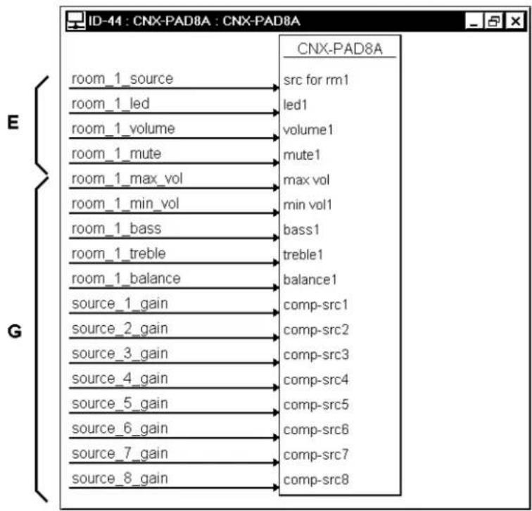
The CNX-PAD8A receives signals from the previously discussed symbols. The CNX-PAD8A receives (E) audio from the selected source, signals to illuminate the front panel LED for Room 1 when it is enabled to receive audio, the audio volume level and mute signal. The remaining inputs (G) are not used in the CNX-PAD8A basic program.
Detail View of CNX-PAD8A Symbol (ID-44) in SIMPL Windows' Programming Manager
flowchart
graph TD
    A["room_1_source"] --> B["src for rm1"]
    C["room_1_led"] --> D["led1"]
    E["room_1_volume"] --> F["volume1"]
    G["room_1_mute"] --> H["mute1"]
    I["room_1_max_vol"] --> J["max vol"]
    K["room_1_min_vol"] --> L["min vol1"]
    M["room_1_bass"] --> N["bass1"]
    O["room_1_treble"] --> P["treble1"]
    Q["room_1_balance"] --> R["balance1"]
    S["source_1_gain"] --> T["comp-src1"]
    U["source_2_gain"] --> V["comp-src2"]
    W["source_3_gain"] --> X["comp-src3"]
    Y["source_4_gain"] --> Z["comp-src4"]
    AA["source_5_gain"] --> AB["comp-src5"]
    AC["source_6_gain"] --> AD["comp-src6"]
    AE["source_7_gain"] --> AF["comp-src7"]
    AG["source_8_gain"] --> AH["comp-src8"]
Problem Solving
Troubleshooting
The table below provides corrective action for possible trouble situations. If further assistance is required, please contact a Crestron customer service representative.
CNX-PAD8A Troubleshooting
| TROUBLE | POSSIBLE CAUSE(S) | CORRECTIVE ACTION |
| PWR LED does not illuminate. | CNX-PAD8A is not receiving power. | Verify that cable plugged into NET port is secure. |
| NET LED does not illuminate. | Loose network connection. | Verify that cables plugged into NET port is secure. |
| Improper NET ID. Verify that CNX-PAD8A NET ID matches NET ID software program. Refer to "Identity Code". | ||
| ROOM 1-8 LED does not illuminate. | Improper programming. | Confirm signal names and programming logic so that LEDs respond when functions are activated. |
| Hum on audio. Grounding problem. Either connect or remove chassis ground wire. | ||
Further Inquiries
If after reviewing this Operations Guide for the CNX-PAD8A, you cannot locate specific information or have questions, please take advantage of Crestron's award winning customer service team in your area. Dial one of the following numbers.
- In the US and Canada, call Crestron's corporate headquarters at 1-888-CRESTRON [1-888-273-7876].
• In Europe, call Crestron International at +32-15-50-99-50.
• In Asia, call Crestron Asia at +852-2341-2016.
• In Latin America, call Crestron Latin America at +5255-5093-2160. - In Australia and New Zealand, call Crestron Control Solutions at +61-2-9737-8203.
Future Updates
As Crestron improves functions, adds new features, and extends the capabilities of the CNX-PAD8A, additional information and programming examples may be made available as manual updates. These updates are solely electronic and serve as intermediary supplements prior to the release of a complete technical documentation revision.
The Downloads page of the Crestron website (www.crestron.com) directs the reader to the location and description of each update. Check the site periodically for update availability and its relevance.
Return and Warranty Policies
Merchandise Returns / Repair Service
- No merchandise may be returned for credit, exchange, or service without prior authorization from CRESTRON. To obtain warranty service for CRESTRON products, contact the factory and request an RMA (Return Merchandise Authorization) number. Enclose a note specifying the nature of the problem, name and phone number of contact person, RMA number, and return address.
- Products may be returned for credit, exchange, or service with a CRESTRON Return Merchandise Authorization (RMA) number. Authorized returns must be shipped freight prepaid to CRESTRON, 6 Volvo Drive, Rockleigh, N.J., or its authorized subsidiaries, with RMA number clearly marked on the outside of all cartons. Shipments arriving freight collect or without an RMA number shall be subject to refusal. CRESTRON reserves the right in its sole and absolute discretion to charge a 15% restocking fee, plus shipping costs, on any products returned with an RMA.
- Return freight charges following repair of items under warranty shall be paid by CRESTRON, shipping by standard ground carrier. In the event repairs are found to be non-warranty, return freight costs shall be paid by the purchaser.
CRESTRON Limited Warranty
CRESTRON ELECTRONICS, Inc. warrants its products to be free from manufacturing defects in materials and workmanship under normal use for a period of three (3) years from the date of purchase from CRESTRON, with the following exceptions: disk drives and any other moving or rotating mechanical parts, pan/tilt heads and power supplies are covered for a period of one (1) year; touchscreen display and overlay components are covered for 90 days; batteries and incandescent lamps are not covered.
This warranty extends to products purchased directly from CRESTRON or an authorized CRESTRON dealer. Purchasers should inquire of the dealer regarding the nature and extent of the dealer's warranty, if any.
CRESTRON shall not be liable to honor the terms of this warranty if the product has been used in any application other than that for which it was intended, or if it has been subjected to misuse, accidental damage, modification, or improper installation procedures. Furthermore, this warranty does not cover any product that has had the serial number altered, defaced, or removed.
This warranty shall be the sole and exclusive remedy to the original purchaser. In no event shall CRESTRON be liable for incidental or consequential damages of any kind (property or economic damages inclusive) arising from the sale or use of this equipment. CRESTRON is not liable for any claim made by a third party or made by the purchaser for a third party.
CRESTRON shall, at its option, repair or replace any product found defective, without charge for parts or labor. Repaired or replaced equipment and parts supplied under this warranty shall be covered only by the unexpired portion of the warranty.
Except as expressly set forth in this warranty, CRESTRON makes no other warranties, expressed or implied, nor authorizes any other party to offer any warranty, including any implied warranties of merchantability or fitness for a particular purpose. Any implied warranties that may be imposed by law are limited to the terms of this limited warranty. This warranty statement supersedes all previous warranties.
Trademark Information
All brand names, product names, and trademarks are the sole property of their respective owners. Windows is a registered trademark of Microsoft Corporation. Windows95/98/Me and WindowsNT/2000 are trademarks of Microsoft Corporation.
This page intentionally left blank.



- Professional Audio Distribution Processor
- Operations Guide
- CRESTRON®
- Contents
- Professional Audio Distribution Processor: CNX-PAD8A 1
- Professional Audio Distribution Processor: CNX-PAD8A
- Description
- Functional Description
- CNX-PAD8A Professional Audio Distribution Processor
- Physical Description
- CNX-PAD8A Ports
- NET
- (Chassis Ground)
- SOURCES 1 - 8
- ROOMS 1 - 8
- CNX-PAD8A Indicators
- PWR (Power)
- ROOMS 1-8
- SETUP
- CNX-PAD8A Pushbuttons
- Leading Specifications
- Rack Mounting
- Stacking
- Hookup
- Network Wiring
- Resistance Equation
- Wire Gauge Values
- Identity Code
- Programming
- Programming with the Crestron AppBuilder
- Programming with SIMPL Windows
- Configure CNX-PAD8A Program
- CNX-PAD8A Symbol
- CNX-PAD8A Example Programs
- The CNX-PAD8A Basic Program
- Problem Solving
- Troubleshooting
- Further Inquiries
- Future Updates
- Return and Warranty Policies
- Merchandise Returns / Repair Service
- CRESTRON Limited Warranty
- Trademark Information
Brand : Crestron
Model : CNX-PAD8A
Category : Network switch