
GLXP-SW16 - Network switch Crestron - Free user manual and instructions
Find the device manual for free GLXP-SW16 Crestron in PDF.


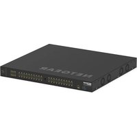
| Product Type | Managed Network Switch |
| Brand | Crestron |
| Model | GLXP-SW16 |
| Port Count | 16 Gigabit Ethernet Ports |
| PoE Support | PoE+ (802.3at) on all ports |
| PoE Budget | 240W total |
| Form Factor | 19-inch Rackmount, 1U |
| Dimensions (W x D x H) | 17.3 x 10.5 x 1.7 inches (44 x 27 x 4.3 cm) |
| Weight | Approximately 5.5 lbs (2.5 kg) |
| Power Supply | Internal, AC 100-240V 50/60Hz |
| Power Consumption | 25W (no PoE), up to 265W max |
| Switching Capacity | 32 Gbps |
| VLAN Support | 802.1Q VLAN, up to 256 groups |
| Management | Web GUI, SNMP, CLI, Crestron Fusion |
| Temperature Range | 32°F to 104°F (0°C to 40°C) |
| Humidity | 10% to 90% non-condensing |
| Safety | UL, CE, FCC Class A |
| Maintenance | Keep vents clean, avoid moisture |
| Spare Parts | Contact Crestron or authorized dealer |
| Repairability | Professional repair only |
Frequently Asked Questions - GLXP-SW16 Crestron
User questions about GLXP-SW16 Crestron
0 question about this device. Answer the ones you know or ask your own.
Ask a new question about this device
Download the instructions for your Network switch in PDF format for free! Find your manual GLXP-SW16 - Crestron and take your electronic device back in hand. On this page are published all the documents necessary for the use of your device. GLXP-SW16 by Crestron.
USER MANUAL GLXP-SW16 Crestron
CRESTRON GREEN LIGHT power switching cabinets come pre-configured with GLXP modules already installed. The cabinets only require installation and wiring of feed and load circuits.
Industry Compliance
The cabinet and modules are Listed to applicable UL Standards and requirements by Underwriters Laboratories Inc.

(E227280 (cabinet) and E103692 (modules))
Application
The following diagram shows CRESTRON GREEN LIGHT cabinets in a lighting application that is controlled by an IPAC system.
CRESTRON GREEN LIGHT Power Switching Cabinets in a Typical Lighting Application

flowchart
graph TD
    A["CRESTRON GREEN LIGHT Cabinet"] -->|Normal Feed| B["GLS-PLS-120/277 Power Loss Sensor"]
    B -->|Override| C["CRESTRON GREEN LIGHT Cabinet"]
    C -->|Cresnet| D["IPAC"]
    D -->|Cresnet| C
    E["ENERGERY TRANSFER SWITCH"] -->|Emergency Feed| B
    F["GENERATOR"] -->|Emergency Feed| B
    G["ELECTRIC UTILITY"] -->|Normal Feed| B
    H["Color Key"] --> I["Override"]
    H --> J["Cresnet"]
    H --> K["AC"]
Physical Description
This section shows the exterior and interior dimensions of the CRESTRON GREEN LIGHT cabinet.
External Dimensions of CRESTRON GREEN LIGHT Power Switching Cabinets
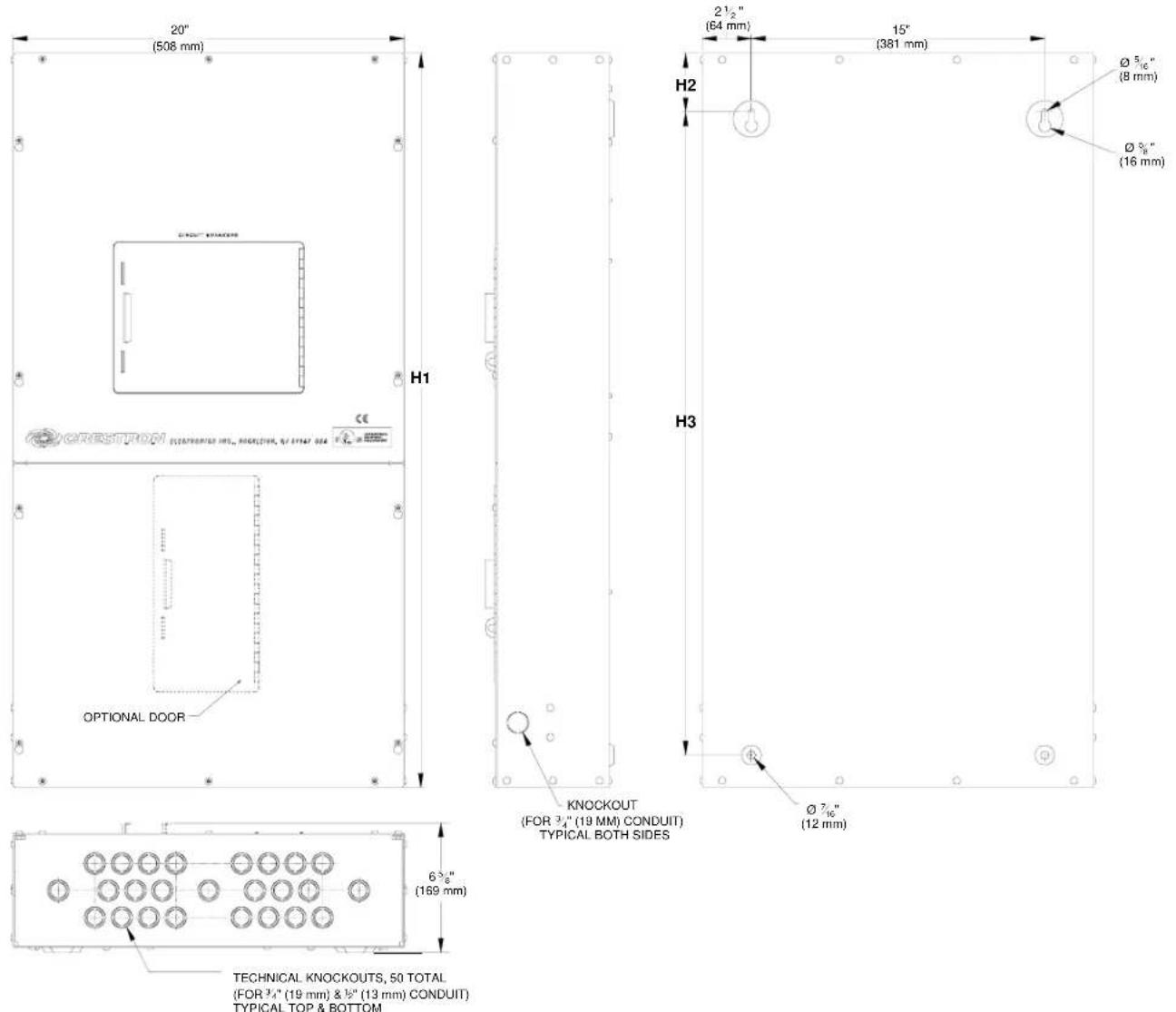
External Dimensions of CRESTRON GREEN LIGHT Power Switching Cabinets
| DIMENSION | 12 Breaker 30 Breaker 42 Breaker 42 Breaker (Short) | |||
| H1 | 37 1/2" 953 mm) | 70" (1.8 m) | 90" (2.3 m) | 78 15/16" (2 m) |
| H2 | 3" (77 mm) | 3 5/8" (93 mm) | 3 5/8" (93 mm) | 3 5/8" (93 mm) |
| H3 | 32 7/8" (836 mm) | 59 3/8" (1.5 m) | 79 3/8" (2.0 m) | 66" (1.7 m) |
Interior Dimensions of CRESTRON GREEN LIGHT Cabinets (120/208 VAC, left; 277/480 VAC, right)


Interior Dimensions of CRESTRON GREEN LIGHT Cabinets
| 120 | Service | |||||
| DIMENSION 12 Breaker 30 Breaker 42 Breaker 12 Breaker 30 Breaker 42 Breaker | ||||||
| H1 | 8 3/4"(223 mm) | 15 1/8"(385 mm) | 18 1/8"(461 mm) | 7 1/16"(180 mm) | 12 1/16"(310 mm) | 15 1/16"(383 mm) |
Installation
Observe the following when installing the cabinet:
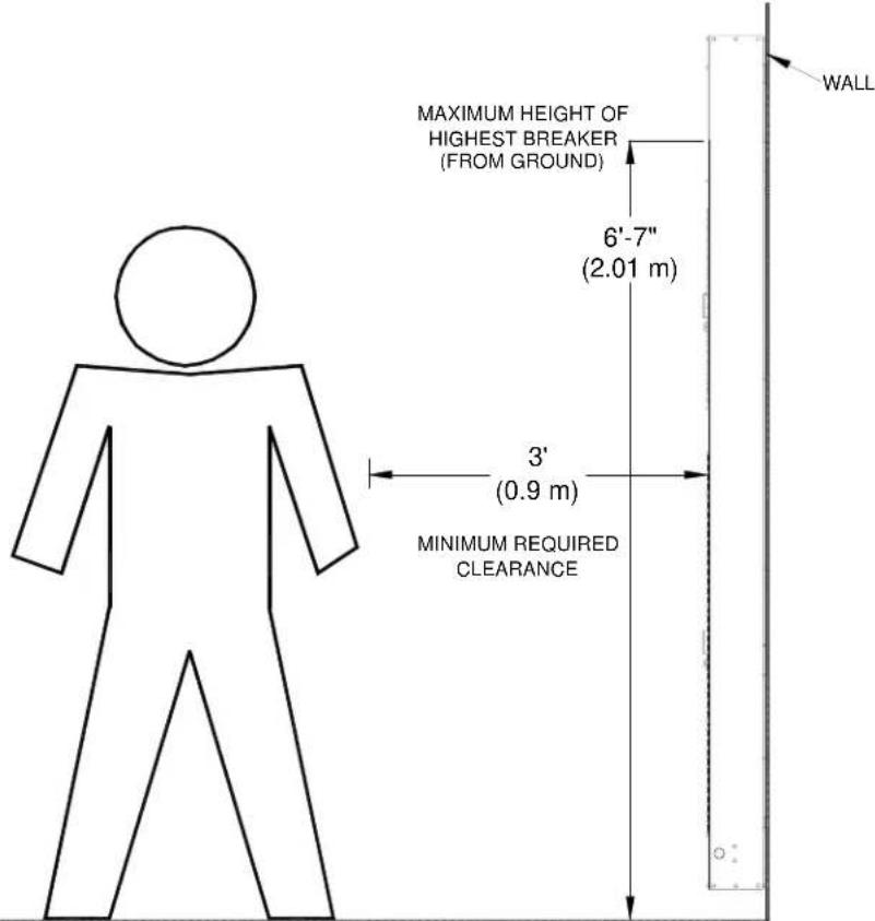
- The cabinet must be mounted by a licensed electrician in accordance with all national and local codes. Refer to the diagram below for specific requirements.
• The cabinet is designed for surface mounting on a wall.
• Cabinets are intended for indoor use only.
- The ambient temperature range should be 32°F to 104°F (0°C to 40°C). The relative humidity should range from 10% to 90% (non-condensing). Allow adequate clearance in front of the cover for servicing.
Mounting Location
Wiring
NOTE: All wiring must be installed in accordance with all local and national electrical codes.
NOTE: Refer to the torque settings specified on pages 6, 7 and 8.
CRESTRON GREEN LIGHT cabinets are shipped with GLXP modules installed and prewired to the branch circuit breakers. The following must be performed after installation:
- Connect incoming feed conductors to the breaker panel (section A of the following diagram)
- Connect load wiring to GLXP module outputs (section B of the following diagram)
- Connect control wiring (section C of the following diagram)

Feed Wiring (Section A)
Feed Wiring for MLO (left) and MCB (right) Applications

Refer to the following table for information on wiring the feed to the panel.
Feed Wire Information
| 120 Volt Models | 277 Volt Models | |||||
| TERMINAL | CONNECTOR MAX TORQUE WIRE RANGE | Max Current | CONNECTOR MAX WIRE RANGE | TORQUE Max Current | ||
| Neutral and Main Lugs | 10-2/0 AWG (CU) or 6-2/0 AWG (AL) | 15 lb-ft(20.3 Nm) | 225 Amps | 6-350 kcmil (CU or AL)1/0-750 kcmil (CU or AL) | 275-300 lb-in(31.1-33.9 Nm) | 250 Amps |
| 6 - 300 kcmil (CU or AL) | 21 lb-ft(28.5 Nm) | |||||
| Neutral Bus 14- | 10 AWG(CU) or 12-10 AWG (AL) | 20 lb-in(2.3 Nm) | 14-6 AWG (CU or AL) | 24-35 lb-in(2.7-4.0 Nm) | ||
| 8 AWG (CU or AL) | 25 lb-in(2.8 Nm) | 14-2/0 AWG (CU or AL) | 40-50 lb-in(4.5-5.6 Nm) | |||
| 6-4 AWG (CU or AL) | 35 lb-in(4.0 Nm) | |||||
| Use copper or aluminum conductors only – rated 75°C. | ||||||
| WARNING: Failure to properly tighten lugs may result in poor electrical connection and overheating of the terminals. | ||||||
Load Wiring (Section B)
CAUTION: Bypass jumpers are provided on each output to allow testing and to protect the module during installation. The jumper shorts the L and SW terminals so that the load circuit is energized when the branch breaker is on. Do not remove the bypass jumper until all feed and load wiring has been completed, and the circuits have been tested for electrical faults.
NOTE: Use copper conductors only – rated 75°C.
Wire Gauge and Torque Values
| TERMINAL CONNECTOR MAX WIRE RANGE TORQUE STRIP LENGTH | |||
| LOAD OUTPUTS 14-10 AWG 4.43 lb-in | (0.5 Nm) | 5/16"(8 mm) | |
| DIM CONTROL(GLXP-DIMFLV8 only) | 28-12 AWG 4.43 lb-in | (0.5 Nm) | 5/16"(8 mm) |
| GROUND BAR 14-10 AWG | 35 lb-in | (4.0 Nm) | 5/16"(8 mm) |
| GROUND LUG 14-4 AWG | 45-25 lb-in | (5.1-2.8 Nm) | 3/4"(19 mm) |
- Each output has a label with the number of the controlling circuit breaker printed on it. With the corresponding circuit breaker turned off, connect the controlled circuit (LOAD) wires to the output per the markings on the module as shown in the following diagrams. Terminals for load wiring accept one 10 – 14 AWG wire.
Load Wiring for GLXP-SW10, GLXP-SW16, GLXP-HSW8, GLXP-HSW12, and GLXP-DIMFLV8 (Jumper Installed)

* A NEUTRAL connection is only present on OUTPUT 1.
The GLXP-DIMFLV8 also requires wiring the terminals for 0-10 VDC control wire. Refer to the following diagram when connecting the dimmable ballast. Each control wire terminal accepts one 12 - 28 AWG wire.
0-10 VDC Control Wiring for GLXP-DIMFLV8 Only

-
Test the circuit for electrical faults by turning on each circuit breaker, checking that the breakers do not trip, and that power is delivered to the proper loads.
-
Turn off the circuit breaker(s) and remove all jumpers.
-
Turn on the circuit breakers.
Control Wiring (Section C)
The bottom of the cabinet contains Cresnet ^® connections for interfacing to the rest of the Crestron ^® control system. It also provides an override input which can be tied to devices such as the GLS-PLS-120/277 phase-loss sensor, or other devices that provide a dry contact closure (manual switch, fire alarm relay, etc.).
NOTE: Interface connectors for NET (x2), POWER (x1), and OVERRIDE (x1) ports are provided.
Wire Gauge and Torque Values
| TERMINAL | CONNECTOR MAX WIRE RANGE | TORQUE | STRIP LENGTH | |
| NET | 12 | AWG | 4.43 lb-in(0.5 Nm) | 1/4"(6 mm) |
| POWER 26-12 | AWG | 4.43 lb-in(0.5 Nm) | 1/4"(6 mm) | |
| OVERRIDE | 26-12 | AWG | 4.43 lb-in(0.5 Nm) | 1/4"(6 mm) |

NET Port Wiring
When wiring the supplied NET connectors for connection to a Crestron control system or other device on the Cresnet network, use Crestron certified wire such as CRESNET-NP or CRESNET-P.
To ensure optimum performance over the full range of your installation topology, use Crestron certified wire. Failure to do so may incur additional charges if support is required to identify performance deficiencies because of using improper wire.
When daisy-chaining connections between NET ports, strip the ends of the wires carefully to avoid nicking the conductors. Twist together the ends of the wires that share a pin on the network connector, insert the connection into the Cresnet connector, and tighten the retaining screw. Repeat the procedure for the other three conductors.
POWER Port Wiring
Low voltage (24 VDC) power must be supplied to the modules either internally via devices connected to the NET port or externally via a Cresnet power supply connected to the POWER port.
To power the modules internally from line power, install a jumper from the INT pin on the supplied POWER connector to the EXT pin on the POWER connector as shown in the following diagram.
Providing Cresnet Power Internally
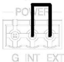
When a lighting module is powered from line power, the module's PWR LED will illuminate.
To power the modules externally from a Cresnet 24 VDC power supply, connect the external power supply to the EXT and G pins on the POWER supplied connector as shown in the following diagram.
Providing Cresnet Power Externally
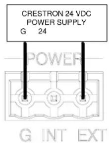
When properly connected and receiving 24 VDC power externally, the green LED next to the MODULES port will light.
When a lighting module is powered from a Cresnet power supply in the absence of line power, the module's PWR LED will flash.
OVERRIDE Port Wiring
Low-voltage input devices such as the Crestron GLS-PLS-120/277 phase-loss sensor or any device that provides a dry contact closure can be connected to the supplied OVERRIDE connector on the bottom of the cabinet.
Testing
Manual Control
A lighting module can be manually controlled from its front panel.
GLXP-SW and GLXP-HSW Modules:
The state of each output can be manually controlled from the front panel.
To toggle the output between off and on, tap the appropriate ON/OFF button. The corresponding LED illuminates and the output state is shown on the NET ID display (“oF” for off, “On” for on) for two seconds after the button is released.
NOTE: The control system program may change the settings if the Override mode is not enabled.
GLXP-DIMFLV8 Modules:
The lighting level of each of the outputs can be manually controlled from the front panel.
To toggle the light between off and 100% (on), tap an output's ON/OFF button. The corresponding LED illuminates and the output level is shown on the NET ID display ("oF" for off, "On" for on) for two seconds after the button is released.
To ramp the lighting level up or down (until it reaches a limit), press and hold the output's ON/OFF button. To change the ramp direction, release the output's ON/OFF button, then press and hold it again. The corresponding LED illuminates and the output level is shown on the NET ID display as a percentage (01-99) for two seconds after the button is released.
NOTE: The control system program may change the settings if the Override mode is not enabled.
Override Mode
The Override mode overrides the control system program and sets all of the output states to the stored override values. For instructions on saving override settings, refer to “Save Override Settings” below.
To enable Override mode, press and release the OVR button. The OVR LED flashes slowly.
NOTE: If the Override mode was enabled from an external device (i.e. a contact closure is present on the OVERRIDE terminals), the OVR LED will flash quickly. Pressing the OVR button has no effect.
To disable Override mode, press the OVR button again. The OVR LED extinguishes and the outputs return to the states set by the control system program.
NOTE: If override states have not been stored, the factory default override state is all loads on.
Save Override Settings
The state of each output can be saved as an override setting, which can be automatically recalled when the Override mode is enabled.
NOTE: The control system program has a setting that can prevent locally saving the override state. If this setting is enabled, the display shows “Er” when trying to save override states. For more information, refer to the SIMPL Windows help file.
To save the state of all of the outputs as an override setting, press and hold the OVR button for three seconds. The OVR LED blinks to indicate the new override settings have been stored.
System Operation and Commissioning
This cabinet has been designed as a component of a programmed Crestron system. System commissioning by an authorized Crestron representative must be performed to ensure system operation.
Once the cabinet has been wired and the modules have been tested, contact Crestron at 1-888-CRESTRON [1-888-273-7876] to schedule commissioning.
Problem Solving
Troubleshooting
The following table provides corrective action for possible trouble situations. If further assistance is required, please contact a Crestron customer service representative.
Troubleshooting
| TROUBLE POSSIBLE CAUSE(S) CORRECTIVE ACTION | ||
| Module(s) does not function. | Power not delivered to the module. | If the module is powered internally, verify that the circuit breaker connected to the first channel on the module is on and delivering power to the module.If module is powered externally, verify that the POWER port is correctly wired and receiving power. |
| System commissioning not complete. | Arrange for system commissioning. | |
| Module's PWR LED is flashing. | AC power not present on L1. | Check that the branch breaker feeding L1 has not tripped. Note that unit will continue to function, but will draw power from the backup Cresnet power supply. |
| Unit cannot be taken out of Override mode | Short (contact closure) exists between G and OVR terminals on any of the OVERRIDE terminals present at bottom of the cabinet. | Determine the reason for the short. Remove or remedy the short (e.g. GLS-PLS-120/277 phase-loss sensor may not have been installed properly, or actual phase-loss has been detected). |
| Fluorescent lamps stay at minimum intensity (0-10V dimmable fluorescents only). | + or - wires are reversed or shorted. | Verify polarity of + and - wires at ballasts and GLXP-DIMFLV8. |
| Fluorescent lamps stay at maximum intensity (0-10V dimmable fluorescents only). | + or - wires are not connected. | Verify polarity of + and - wires at ballasts and GLXP-DIMFLV8. |
Further Inquiries
If you cannot locate specific information or have questions after reviewing this guide, please take advantage of Crestron's award winning customer service team by calling Crestron at 1-888-CRESTRON [1-888-273-7876].
You can also log onto the online help section of the Crestron website (www.crestron.com/onlinehelp) to ask questions about Crestron products. First-time users will need to establish a user account to fully benefit from all available features.
Appendix A: Setting Module Net IDs
The following procedure will normally be performed by an authorized Crestron representative as part of the System Commissioning phase. For system wiring and basic testing as described on pages 5 and 11, it is not necessary to perform this step. Only perform this step if instructed by an authorized Crestron representative, or when replacing modules on a system that have already been commissioned (in the latter case the Net ID should be set to match the Net ID of the module being replaced).
The Net ID of each module in the cabinet can be changed from the front panel of each module. The Net IDs of each module in the system must be unique.
To set the Net ID using the front panel:
-
Press the recessed SETUP button to enter the Setup mode. The SETUP LED illuminates.
-
As shown in the following diagram, press the left button under the NET ID display to change the left digit of the Net ID or press the right button under the NET ID display to change the right digit of the Net ID number.
Changing the Net ID

- When the desired Net ID is displayed, press the SETUP button to exit the Setup mode. The SETUP LED extinguishes.
If the SETUP button is not pressed, the Setup mode will time out after one minute activity and the Net ID will revert back to its original value.
Appendix B: Module Specifications
Specifications for the GLXP modules are listed in the following table.
GLXP Module Specifications
| SPECIFICATION | GLXP-SW10 | GLXP-SW16 | GLXP-HSW8 | GLXP-HSW12 | GLXP-DIMFLV8 |
| Description | 10 Channel Switch Module | 16 Channel Switch Module | 8 Channel High-Inrush Switch Module | 12 Channel High-Inrush Switch Module | 8 Channel 0-10V Fluorescent Dimmer Module |
| Number of Outputs | 10 16 8 12 8 | ||||
| Cresnet Power Usage* | 5 Watts 5 Watts 5 Watts 5 Watts | 5 Watts | |||
| Input Voltage 100 – 277 VAC50/60 Hz | 100 – 277 VAC50/60 Hz | 100 – 277 VAC50/60 Hz | 100 – 277 VAC50/60 Hz | 100 – 277 VAC50/60 Hz | |
| Supported Load Types | Incandescent, Magnetic Low Voltage, Electronic Low Voltage, Neon/Cold Cathode, Fluorescent Ballast, HID, Motor | Incandescent, Magnetic Low Voltage, Electronic Low Voltage, Neon/Cold Cathode, Fluorescent Ballast, HID, Motor | Incandescent, Magnetic Low Voltage, Electronic Low Voltage, Neon/Cold Cathode, Fluorescent Ballast, HID, Motor | Incandescent, Magnetic Low Voltage, Electronic Low Voltage, Neon/Cold Cathode, Fluorescent Ballast, HID, Motor | Dimmable Loads:0-10 VDC dimmable fluorescent ballasts (i.e. Advance Mark 7 or other ballasts that comply with the specifications for control by DC voltage in ANSI C82.11:2002 and IEC60929:2006)Non-Dim Loads:Incandescent, HID, magnetic low voltage (MLV), electronic low voltage (ELV), neon/cold cathode, and fluorescent ballasts, motor |
| Maximum Load LightingMotor | 16 A per output1 HP @ 120V2 HP @ 230/277V | 16 A per output1 HP @ 120V2 HP @ 230/277V | 16 A per output 12 HP @ 120V1 HP @ 230V,1 HP @ 277V | 16 A per output 12 HP @ 120V1 HP @ 230V,1 HP @ 277V | 16 A per output 12 HP @ 120V1 HP @ 230V,1 HP @ 277V |
| Environmental TemperatureHumidityHeat Dissipation | 32^ to 104^ F( 0^ to 40^ C)10% to 90% RH(non-condensing)10 BTU/Hr | 32^ to 104^ F( 0^ to 40^ C)10% to 90% RH(non-condensing)10 BTU/Hr | 32^ to 104^ F( 0^ to 40^ C )10% to 90% RH(non-condensing)10 BTU/Hr | 32^ to 104^ F( 0^ to 40^ C )10% to 90% RH(non-condensing)10 BTU/Hr | 32^ to 104^ F ( 0^ to 40^ C )10% to 90% RH(non-condensing)10 BTU/Hr |
* Power usage will be zero whenever AC power is present on circuit 1 on the module. Use of Cresnet power is optional.
Return and Warranty Policies
Merchandise Returns / Repair Service
- No merchandise may be returned for credit, exchange or service without prior authorization from CRESTRON. To obtain warranty service for CRESTRON products, contact an authorized CRESTRON dealer. Only authorized CRESTRON dealers may contact the factory and request an RMA (Return Merchandise Authorization) number. Enclose a note specifying the nature of the problem, name and phone number of contact person, RMA number and return address.
- Products may be returned for credit, exchange or service with a CRESTRON Return Merchandise Authorization (RMA) number. Authorized returns must be shipped freight prepaid to CRESTRON, 6 Volvo Drive, Rockleigh, N.J. or its authorized subsidiaries, with RMA number clearly marked on the outside of all cartons. Shipments arriving freight collect or without an RMA number shall be subject to refusal. CRESTRON reserves the right in its sole and absolute discretion to charge a 15% restocking fee plus shipping costs on any products returned with an RMA.
- Return freight charges following repair of items under warranty shall be paid by CRESTRON, shipping by standard ground carrier. In the event repairs are found to be non-warranty, return freight costs shall be paid by the purchaser.
CRESTRON Limited Warranty
CRESTRON ELECTRONICS, Inc. warrants its products to be free from manufacturing defects in materials and workmanship under normal use for a period of three (3) years from the date of purchase from CRESTRON, with the following exceptions: disk drives and any other moving or rotating mechanical parts, pan/tilt heads and power supplies are covered for a period of one (1) year; touchscreen display and overlay components are covered for 90 days; batteries and incandescent lamps are not covered.
This warranty extends to products purchased directly from CRESTRON or an authorized CRESTRON dealer. Purchasers should inquire of the dealer regarding the nature and extent of the dealer's warranty, if any.
CRESTRON shall not be liable to honor the terms of this warranty if the product has been used in any application other than that for which it was intended or if it has been subjected to misuse, accidental damage, modification or improper installation procedures. Furthermore, this warranty does not cover any product that has had the serial number altered, defaced or removed.
This warranty shall be the sole and exclusive remedy to the original purchaser. In no event shall CRESTRON be liable for incidental or consequential damages of any kind (property or economic damages inclusive) arising from the sale or use of this equipment. CRESTRON is not liable for any claim made by a third party or made by the purchaser for a third party.
CRESTRON shall, at its option, repair or replace any product found defective, without charge for parts or labor. Repaired or replaced equipment and parts supplied under this warranty shall be covered only by the unexpired portion of the warranty.
Except as expressly set forth in this warranty, CRESTRON makes no other warranties, expressed or implied, nor authorizes any other party to offer any warranty, including any implied warranties of merchantability or fitness for a particular purpose. Any implied warranties that may be imposed by law are limited to the terms of this limited warranty. This warranty statement supersedes all previous warranties.
Trademark Information
All brand names, product names and trademarks are the sole property of their respective owners. Windows is a registered trademark of Microsoft Corporation. Windows95/98/Me/XP/Vista and WindowsNT/2000 are trademarks of Microsoft Corporation.



- Industry Compliance
- Application
- Physical Description
- Installation
- Wiring
- Feed Wiring (Section A)
- Load Wiring (Section B)
- Control Wiring (Section C)
- NET Port Wiring
- POWER Port Wiring
- OVERRIDE Port Wiring
- Testing
- Manual Control
- Override Mode
- Save Override Settings
- System Operation and Commissioning
- Problem Solving
- Troubleshooting
- Further Inquiries
- Appendix A: Setting Module Net IDs
- Appendix B: Module Specifications
- Return and Warranty Policies
- Merchandise Returns / Repair Service
- CRESTRON Limited Warranty
- Trademark Information
Brand : Crestron
Model : GLXP-SW16
Category : Network switch