
FT-TS600-B - Touch Controller Crestron - Free user manual and instructions
Find the device manual for free FT-TS600-B Crestron in PDF.


| Product Type | Touch Screen Controller |
| Brand | Crestron |
| Model | FT-TS600-B |
| Display Size | 6-inch diagonal |
| Display Resolution | 640 x 480 pixels |
| Touch Technology | Resistive touchscreen |
| Processor | 32-bit ARM Cortex-A8 |
| Memory | 512 MB RAM, 4 GB Flash |
| Ethernet | 10/100 Mbps, PoE+ (802.3at) |
| USB | 1 x USB 2.0 Host |
| Audio | Built-in speaker and microphone |
| Operating System | Crestron Linux |
| Power Source | PoE+ or external 12V DC adapter |
| Power Consumption | 15W maximum |
| Dimensions (W x H x D) | 7.5 in x 5.3 in x 2.2 in (190 mm x 135 mm x 56 mm) |
| Weight | 1.2 lb (0.54 kg) |
| Mounting Options | Wall mount or desk stand (optional) |
| Cleaning | Wipe with a soft, dry cloth. Do not use liquids or abrasives. |
| Safety | UL listed, CE marked, RoHS compliant |
| Spare Parts | Contact Crestron authorized service centers for replacement parts. |
| Repairability | Repairs must be performed by Crestron certified technicians. |
Frequently Asked Questions - FT-TS600-B Crestron
User questions about FT-TS600-B Crestron
0 question about this device. Answer the ones you know or ask your own.
Ask a new question about this device
Download the instructions for your Touch Controller in PDF format for free! Find your manual FT-TS600-B - Crestron and take your electronic device back in hand. On this page are published all the documents necessary for the use of your device. FT-TS600-B by Crestron.
USER MANUAL FT-TS600-B Crestron
Installing the Bushings
The Crestron® FT-TS600 ships with two cable management plates preinstalled. These provide a pullout cable solution for the AUD OUT (audio output), COMPUTER, and LAN cables. A 6 foot (1.8 meter) USB type A to type B cable is included for the COMPUTER connection. Cables are looped through the cable management plates.
The included bushings must be installed before mounting the FT-TS600 into a surface. For a neat appearance, any unused openings can be filled using the included hole plugs. The only tool required to install the bushings is a Phillips screwdriver.
- Remove the two cable management plates and retain the two 06-32 x 1/4" screws.
- Place the bushings on the cables (eight bushings supplied).
- Thread the cables through the appropriate slots in each cable management plate.
- Snap the bushings into the cable management plate slots.
- Feed all excess cable through the bushings.
- Attach each cable management plate by sliding the dovetail into the slot shown below, dropping the front of the cable management plate into place, and then securing the cable management plate with the 06-32 x 1/4" screw from step 1.

Mounting into a Surface
The FT-TS600 is designed to mount into a horizontal surface, such as a desktop, lectern, or podium. The following diagram illustrates the required cutout dimensions to accommodate the FT-TS600.

NOTE: Before inserting the FT-TS600 into the mounting hole, ensure that all require cables have been installed.
The only tools required are a Phillips screwdriver and a #10 Allen wrench. To mount the FT-TS600, use the following procedure:
- Position the FT-TS600 in the mounting hole.
- Install the four included 10-32 x 2" socket screws in the metal mounting plates (two screws per plate).
- Slide the moutning plates over the studs on each side of the FT-TS600.
DO Check the Box
QTY PRODUCT PART NUM.
| 2 Mounting Plates 2036985 | |
| 4 Screws, 10-32 x 2", Socket 2037109 | |
| 4 Small Hole Plugs 2036647 | |
| 4 Large Hole Plugs 2036649 | |
| 4 Small Bushings 2009522 | |
| 4 Large Bushings 2010496 | |
| 1 Connector, 3-Pin | 2003575 |
| 1 Cable, USB 2.0, A-B, 6' (1.8 m) | 2014966 |
| 1 Cutout Template | 4519221 |

Studs for the Mounting Plate Surface Cutout
- Turn the four 10-32 x 2" socket screws equally until they contact the underside of the mounting surface.
NOTE: Do not overtighten the screws because this may damage the surface or the unit.


DO Connect the Device
Make the necessary connections as called out in the illustration that follows.
When making connections to the FT-TS600, note the following:
- Use Crestron power supplies for Crestron equipment.
- The included cable cannot be extended.
AUD OUT: LAN PoE:
To Balanced 10BASE-T / 100BASE-TX
Line Level Input Ethernet to LAN
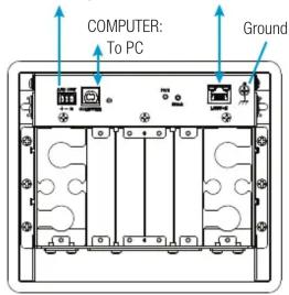
CAUTION: Do not apply excessive pressure to the touch screen display during handling. Doing so can crack the screen and damage the device.
NOTE: Ensure the unit is properly grounded by connecting the chassis ground lug to an eargh ground (building steel).
DO Access the Setup Screens
NOTE: The FT-TS600 can take up to 45 seconds to boot.
NOTE: If no project has been loaded or if an invalid project has been loaded, the screen displays the following message: "There is no display project to start. [Touch Screen to Enter Setup...]."
The setup screens enable basic configuration prior to regular operation of the FT-TS600.
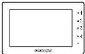
During regular operation of the touch screen, there are two ways to access the setup screens:
- Place a button on the project main page and assign the reserved join number (17242) that accesses the setup screens.
- Press hard keys 1, 2, 3, and 4 on the right side of the touch screen display in sequence twice (press 1, 2, 3, 4, 1, 2, 3, 4) within a 5 second period.
DO Learn More
Visit the website for additional information and the latest firmware updates.
Crestron Electronics
15 Volvo Drive, Rockleigh, NJ 07647
888.CRESTRON | www.crestron.com

CE

As of the date of manufacture, the product has been tested and found to comply with specifications for CE marking.
This product is Listed to applicable UL Standards and requirements by Underwriters Laboratories, Inc.
Federal Communications Commission (FCC) Compliance Statement
This device complies with part 15 of the FCC Rules. Operation is subject to the following two conditions:
(1) This device may not cause harmful interference, and (2) this device must accept any interference received, including interference that may cause undesired operation.
Caution: Changes or modifications not expressly approved by the manufacturer responsible for compliance could void the user's authority to operate the equipment.
Note: This equipment has been tested and found to comply with the limits for a Class B digital device, pursuant to part 15 of the FCC Rules. These limits are designed to provide reasonable protection against harmful interference in a residential installation. This equipment generates, uses and can radiate radio frequency energy and, if not installed and used in accordance with the instructions, may cause harmful interference to radio communications. However, there is no guarantee that interference will not occur in a particular installation.
If this equipment does cause harmful interference to radio or television reception, which can be determined by turning the
equipment off and on, the user is encouraged to try to correct the interference by one or more of the following measures:
• Reorient or relocate the receiving antenna
- Increase the separation between the equipment and receiver
- Connect the equipment into an outlet on a circuit different from that to which the receiver is connected
- Consult the dealer or an experienced radio/TV technician for help
Industry Canada (IC) Compliance Statement
CAN ICES-3(B)/NMB-3(B)
Crestron product development software is licensed to Crestron dealers and Crestron Service Providers (CSPs) under a limited non-exclusive, non-transferable Software Development Tools License Agreement. Crestron product operating system software is licensed to Crestron dealers, CSPs, and end-users under a separate End-User License Agreement. Both of these Agreements can be found on the Crestron website at www.crestron.com/legal/software_license_agreement.
The specific patents that cover Crestron products are listed at patents.crestron.com.
The product warranty can be found at www.crestron.com/warranty.
Crestron and the Crestron logo are either trademarks or registered trademarks of Crestron Electronics, Inc. in the United States and/or other countries. UL and the UL logo are either trademarks or registered trademarks of Underwriters Laboratories, Inc. in the United States and/or other countries. Other trademarks, registered trademarks, and trade names may be used in this document to refer to either the entities claiming the marks and names or their products. Crestron disclaims any proprietary interest in the marks and names of others. Crestron is not responsible for errors in typography or photography.
This document was written by the Technical Publications department at Crestron.
©2015 Crestron Electronics, Inc.

CRESTRON. DO GUIDE
DOC. 7784A (2043774) 04.15
Specifications subject to change without notice.
Brand : Crestron
Model : FT-TS600-B
Category : Touch Controller