
RGB 192V - Audio/video converter Extron - Free user manual and instructions
Find the device manual for free RGB 192V Extron in PDF.


| Product Type | Analog Computer-Video Interface (Audio/Video Converter) |
| Model | RGB 192V (PC version) |
| Video Bandwidth | 300 MHz (-3 dB) |
| Video Input | 1 analog VGA-UXGA, RGBHV, RGBS, RGsB via 15-pin HD female |
| Video Output | 1 RGBHV, RGBS, or RGsB via 6 BNC female connectors |
| Local Monitor Output | 1 buffered loop-through on 15-pin HD female |
| Audio Input | 1 unbalanced stereo via 3.5 mm mini stereo jack (tip, ring, sleeve) |
| Audio Output | 1 balanced/unbalanced stereo or mono via 3.5 mm 5-pole captive screw connector |
| Sync Processing | Digital Display Sync Processing (DDSP) with selectable serration pulses, sync on green (SOG), and H-shift control |
| Front Panel Controls | Horizontal shift, Level (boost) DIP switch, and 6 DIP switches for mode selection |
| Power Supply | External, 100-240 VAC, 50/60 Hz, output 12 VDC, 1 A (included) |
| Power Consumption (Device) | 12 VDC, 0.35 A (4.2 W) |
| Dimensions (H x W x D) | 1.0" x 5.7" x 4.5" (2.5 cm x 14.5 cm x 11.4 cm) |
| Weight (Product) | 0.9 lbs (0.4 kg) |
| Mounting Options | Tabletop, under-desk (brackets included), through-desk (optional kit) |
| Included Accessories | VGA M 6' MHR cable, under-desk mounting kit, rubber feet, external power supply, captive screw connector |
| Compliance | CE, FCC Class A, VCCI, AS/NZS, ICES, UL, CUL |
| Warranty | 3 years parts and labor |
| Operating Temperature | +32° to +122°F (0° to +50°C) |
| Storage Temperature | -40° to +158°F (-40° to +70°C) |
Frequently Asked Questions - RGB 192V Extron
User questions about RGB 192V Extron
0 question about this device. Answer the ones you know or ask your own.
Ask a new question about this device
Download the instructions for your Audio/video converter in PDF format for free! Find your manual RGB 192V - Extron and take your electronic device back in hand. On this page are published all the documents necessary for the use of your device. RGB 192V by Extron.
USER MANUAL RGB 192V Extron
Extron. Electronics INTERFACING, SWITCHING AND DISTRIBUTION

User's Manual


RGB 190F RGB 192 RGB 198
Analog Computer-Video Interface
68-647-01 Rev. D 05 06

www.288.com
Extrun Electronics, USA
1250 South Lawit Street
Analysin, CA 2905
USA
714491.190
Fax 714191-517
Estron Electronics, Europa
Beddeberawar 6C
3821AH Augofoer
The Netherlands
+31.51454040
Fax:31-33,455-4050
Extron Electronics Asia
135 Jan Seng Road 40+
PS Industrial Building
Sinamar 3684
+656581.4400
Fax:65-6383-6564
Eatron Electronics, Jarsin
Kyoda Buildfire
16 Ichuban
Cawasaki, Tokyo 192-0082 Japan
+813.5511.7655
Precautions
Safety Instructions • English

This symbol is intended to alert the user of important operating and maintenance (servicing) instructions in the literature provided with the equipment.

This symbol is intended to alert the user of the presence of uninsulated dangerous voltage within the product's enclosure that may present a risk of electric shock.
Caution
Road Instructions • Read and understand safety and operating equipment before water the equipment.
Return Instructions • Do not try instructions should be kept for future performance.
Follow Earnings • Follow all warnings and instructions reported on the following section:
Avoid Attachments • No not use Track or Attachments that are not
recommended by the equipment manufacturer because they may be reasonable.
Please refer to "This equipment should be operated only from the same source indicated on the product. This component is intended to be used with a random power system, a guaranteed (annual) conductive. The third (grounding) part of a safety feature, do not attempt to impose or disable it."
Power disconnection + To remove power from the equipment safety, remove all power sends from the rear of the equipment, or the cookup power module (it detached), or from the power source receptacle (well plug)
Prave credit protection. * Power cards should be mailed so that they are not liable to be swapped on or inserted by items placed upon or against them.
Surprising * Reliant surviving to qualified service personnel. There are no inter-servатель's public intake. To prevent the risk of shock, do not attempt to survive the equipment yourself during opening or removing cover may impose you to dangerous voltage or other hazards.
Slots and openings • If the equipment has colour holes in the one waste, there are provided to prevent overfunding of suitable components that. Thus openings must never be blocked by other objects.
Lithium battery - Type is a danger of exception if battery is incorrectly replaced. Displace a only with the same equivalent type recommended by the manufacturer. Displace of used battery according to the manufacturer's instructions.
Avertissement
Note: This equipment has been tested and found to comply with the limits for a Class A digital device, pursuant to part 15 of the FCC Rules. These limits are designed to provide reasonable protection against harmful interference when the equipment is operated in a commercial environment. This equipment generates, uses and can radiate radio frequency energy and, if not installed and used in accordance with the instruction manual, may cause harmful interference to radio communications. Operation of this equipment in a residential area is likely to cause harmful interference, in which case the user will be required to correct the interference at his own expense.
Note: This unit was tested with shielded cables on the peripheral devices. Shielded cables must be used with the unit to ensure compliance.
Extron's Warranty
Extron Electronics warrants this product against defects in materials and workmanship for a period of three years from the date of purchase. In the event of malfunction during the warranty period attributable directly to faulty workmanship and/or materials, Extron Electronics will, at its option, repair or replace said products or components, to whatever extent it shall deem necessary to restore said product to proper operating condition, provided that it is returned within the warranty period, with proof of purchase and description of malfunction to:
USA, Canada, South America, Europe, Africa, and the Middle East; and Central America:
Extron Electronics Beeldschermweg 6C 1001 East Ball Rd. 3821 AHI Amersfoort Anaheim, CA 92805, USA The Netherlands
Asia: Japan:
Extron Electronics, Asia Extron Electronics, Japan
135 Joo Seng Road, #04-01 Kyoko Building
PM Industrial Bldg. 16 Ichibancho
Singapore 368363 Chiyoda-ku, Tokyo 102-0082
Japan
This Limited Warranty does not apply if the fault has been caused by misuse, improper handling care, electrical or mechanical abuse, abnormal operating conditions or non-Extron authorized modification to the product.
If it has been determined that the product is defective, please call Extron and ask for an Applications Engineer at (714) 491-1500 (USA), 31.33.453.4040 (Europe), 65.6383.4400 (Asia), or 81.3.3511.7655 (Japan) to receive an RA# (Return Authorization number). This will begin the repair process as quickly as possible.
Units must be returned insured, with shipping charges prepaid. If not insured, you assume the risk of loss or damage during shipment. Returned units must include the serial number and a description of the problem, as well as the name of the person to contact in case there are any questions.
Extron Electronics makes no further warranties either expressed or implied with respect to the product and its quality, performance, merchantability, or fitness for any particular use. In no event will Extron Electronics be liable for direct, indirect, or consequential damages resulting from any defect in this product even if Extron Electronics has been advised of such damage.
Please note that laws vary from state to state and country to country, and that some provisions of this warranty may not apply to you.
安全须知 · 中文

About this Manual 1-2
About the RGB 190F, RGB 192, and RGB 198 ..... 1-2
Features 1-3
Chapter 2 • Installation and Operation ..... 2-1
Installation Overview 2-2
Mounting the Interfaces 2-2
Tabletop placement.... 2-2
Under-desk mounting 2-2
Through-desk mounting 2-3
Rack mounting (RGB 198 only) 2-4
Connections and Switches 2-5
Operation and Troubleshooting 2-10
If the image does not appear or there is no sound ..... 2-10
If the image is not displayed correctly 2-11
If the interface does not respond to controls.... 2-11
Appendix • Reference Information ...... A-1
Specifications A-2
Included Parts A-5
Optional Accessories A-6
Cables A-7
68-647-01
Rev. D
05 06
All trademarks mentioned in this manual are the properties of their respective owners.

RGB 190F, RGB 192, and 198
1 Chapter One
Introduction
About this Manual
About the RGB 190F, RGB 192, and RGB 198
Features
Introduction
About this Manual
This manual contains information about the Extron RGB 190F, RGB 192, and RGB 198 universal interfaces, detailing how to operate and configure them. The three interfaces are functionally identical, with the exception of the audio capabilities of the RGB 192 and RGB 198. All interfaces are described in this manual; differences are noted where they exist.
About the RGB 190F, RGB 192 and RGB 198
The RGB 190F, RGB 192, and RGB 198 are analog computer-video interfaces with 300 MHz (-3 dB) video bandwidth and Digital Display Sync Processing™ (DDSP™). Figure 1-1 shows a typical RGB 198 application; as noted above, the RGB 190F and the RGB 192 have a similar setup. The interfaces accept a computer video and an unbalanced computer stereo audio input. They feature a local monitor output and an RGBHV, RGBS or RGsB output. The interfaces feature horizontal centering and level boost. The RGB 192 and RGB 198 also feature a balanced, line level stereo or mono audio output.
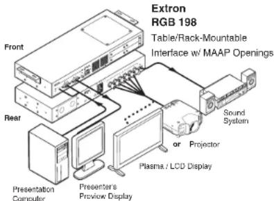
Figure 1-1 — Typical RGB 198 application
All three interfaces allow for furniture and under-desk mounting. The RGB 198 is rack mountable as well. The RGB 190F and RGB 192 have external switching power supplies for worldwide power compatibility, while the RGB 198 provides an internal power supply.
Each RGB interface has two or more model options:
Three RGB 190F models
•RGB 190FV for PC computers
•RGB 190FM for Macintosh computers
•RGB 190FS for SGI computers
Two RGB 192 models
• RGB 192V for PC computers
• RGB 192S for SGI computers
These two models are otherwise identical with the exception of the video input cable supplied.
Two RGB 198 models
•The RGB 198 provides an AC outlet with two Edison plugs.
•The RGB 198 EU provides an AC outlet with two Euro plugs for European markets.
With the appropriate cable adapters, both of these models are compatible with Macintosh computer and SGI computers.
Features
Flexible mounting options — The interface can be mounted under a desk or podium, mounted on a rack (RGB 198 only), or through a desk with optional mounting kits.
Stereo audio (RGB 192 and 198 only) — The interface outputs unbalanced PC stereo audio as line level, balanced stereo (or, depending on a DIP switch position, mono).
Level (boost) control — A front panel control compensates for signal losses from long cable runs.
Horizontal centering control — A front panel control allows a horizontal centering adjustment.
Sync processing — Using regular sync processing to allow centering control (H-shift) can create problems with some digital display devices as a result of the sync delay. Extron's DDSP (Digital Display Sync Processing), ensures proper displays without altering sync pulse timing or width. The sync processing type is selected via the front panel DIP switches.
Introduction, cont'd
RGBHV, RGBS, or RGsB outputs — Select the output format via cabling setup and front panel DIP switch.
Serration pulse switch — This DIP switch-selectable feature adds or strips the serration pulses from the output signal to make it compatible with digital display devices. Use the serration pulse switch if flagging or bending occurs at the top of the video display.

RGB 190F, RGB 192, and 198
Chapter Two
Installation and Operation
Installation Overview
Mounting the Interfaces
Connections and Switches
Operation and Troubleshooting
Installation and Operation
Installation Overview
This is an overview of the installation process. You will find detailed installation and operation instructions in this chapter. Install and set up the RGB 190F, RGB 192, or RGB 198 interfaces by following these basic steps:
1 Turn off all of the equipment (computers, remote controls, interface, projector/monitor, local monitor and speakers or other audio device). Disconnect the power cords from the power source.
2 Install the rubber feet for tabletop use, or install the appropriate brackets to rack mount the interface. See Mounting the Interfaces below.
3 Connect the input (computer video and audio [RGB 192 and 198 only]) and outputs (display, local monitor, and audio [RGB 192 and 198 only]). See Connections and Switches in this chapter.
4 Set the front panel DIP switches. See Connections and Switches, in this chapter, as a guide.
5 Connect power cords and turn on the devices: output devices (projector, monitors, speakers [RGB 192 and 198 only]), interface, and the source computer.
6 Adjust horizontal centering and set the Level DIP switch to obtain the best picture.
Mounting the Interfaces
The interfaces provide several mounting options: tabletop placement, under-desk mounting, through-desk mounting or (for the RGB 198 only) rack mounting. Follow the appropriate procedure on the next three pages.
Tabletop placement
For tabletop or desktop placement only, install the self-adhesive rubber feet/pads (provided) onto the four corners of the bottom of the interface enclosure.
Under-desk mounting
- Secure the included under-desk mounting brackets (part #70-077-01) to the interface with the machine screws that are already installed in the side of the interface (figure 2-1).

Figure 2-1 — Under-desk mounting
- Hold the interface with attached brackets against the underside of the desk or other furniture. Mark the location of holes for screws on the desk.
- Drill pilot holes 1/4" (6.4 mm) deep, and 3/32" (2 mm) diameter in the table or desk at the marked screw locations from the underside/inside (concealed side) of the furniture, where the interface will be located.
- Insert the four wood screws into the pilot holes. Fasten each screw into the installation surface until just less than 1/4" of the screw protrudes.
- Align the installed screws with the slots in the mounting brackets, and place the interface against the surface, with the screws through the bracket slots.
- Slide the interface slightly forward or back, then tighten all four screws to fasten it in place.
Through-desk mounting
- If rubber feet were installed on the interface, remove them.
- Insert the machine screws that are already installed in the side of the interface through the slots in the through-desk mounting brackets (part #70-077-02), and loosely secure the brackets to the interface (figure 2-2).
Installation and Operation, cont'd
- Hold the interface with attached brackets against the underside of the desk/table. With a soft pencil mark the location of holes for screws on the desk based on the following:
For the RGB 190 and RGB 192, mark the opening approximately 1.0" x 5.7" (2.5 cm x 14.5 cm).
For the RGB 198, mark the opening approximately 1.75" x 13.0" (4.5 cm x 33.0 cm).
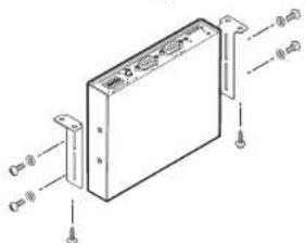
Figure 2-2 — Through-desk mounting
- Cut out the material from the installation area with a jigsaw. Check the opening size by inserting the interface part way through the hole. If needed, use a saw, file or sandpaper to enlarge the hole. Smooth the edges of the hole with sandpaper.
- Drill pilot holes 1/4" (6.4 mm) deep, and 3/32" (2 mm) diameter in the underside or inside (concealed side) of the furniture where the interface will be located.
- Secure the interface to the desk with the provided wood screws.
- To adjust the height of the interface within the desk, slide the interface up or down to the desired position, then tighten the screws that attach the brackets to the interface.
Rack mounting (RGB 198 only)
- Remove rubber feet if they were previously installed on the bottom of the interface.
- Mount the interface on either side of an 19" 1U Universal Rack Shelf (part # 60-190-01) using two 4-40 x 3/16" screws to secure it to the shelf. See figure 2-3.
- Install blank panel(s) or other unit(s) on the rack shelf.
- Attach the rack shelf to the rack using the supplied bolts.
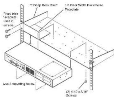
Figure 2-3 — Rack mounting
Connections and Switches
Figures 2-4 and 2-5 show the front and rear panel of the RGB 192 and the RGB 198, respectively. With the exception of audio features (numbers ② and ⑨), all numbers for figure 2-4 pertain to both the RGB 190 and 192 models.
① Power indicator —
Amber — Indicates power is applied.
Green — Indicates that power is applied and a sync signal is present on the input.

Figure 2-4 — RGB 192 front and rear panel features
Installation and Operation, cont'd
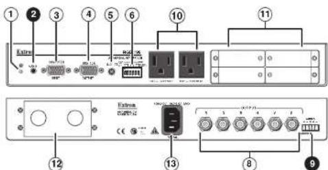
Figure 2-5 — RGB 198 front and rear panel features
2 Audio input (RGB 192 and 198 only) — Connect the unbalanced stereo audio source (such as a computer or a CD player) to this 3.5 mm mini stereo jack for unbalanced audio input. Figure 2-6 shows how to wire the audio jack.

Figure 2-6 — Audio input connector wiring
③ Computer Input — Connect the analog computer-video source to this 15-pin HD female connector.
NOTE Most laptop or notebook computers have an external video port, but they require special commands to output the video to that connector. Also, laptops' screens shut off once that port is activated. See the computer's user's guide for details, or contact Extron for a list of laptop keyboard commands.
④ Monitor Output — If desired, connect a local monitor or other device to this 15-pin HD female connector.
⑤ H( horizontal) Shift — While viewing the displayed image, rotate this control to move the image to the right or left on the screen.
NOTE DDSP disables the interface's Horizontal Shift control.
To use the display's centering controls instead of the interface's controls, set the DDSP DIP switch to On.
⑥ DIP switches — This bank of DIP switches is used to configure the interface. The switches control:
- Level
- SOG (sync on green)
- Serration pulses
D D S P
• Monitor or no monitor (ID bit termination)
• Mono or stereo audio (RGB 192 and 198 only, spare on RGB 190F)
NOTE The default for all DIP switches is Off (down).
1 — Level (and peaking)
The Level control alters the video output voltage to affect the brightness of the displayed image. Turn the switch on and off while viewing the displayed image to set the level that provides the best picture quality. If the interface receives a typical (0.7 volts p-p) analog computer video input, the output is as follows:
On — 0.8 volts p-p with peaking
Off — 0.7 volts p-p
2 — Sync on green
On — The interface outputs a composite sync signal on top of the green video signal (SOG) via the G output connector (RGsB).
Off — The interface outputs separate horizontal and vertical sync (on the 11 and V connectors) and composite sync (on the S connector) for RGBHV or RGBS.
3 — Serration pulses — Many LCD and DLP projectors and plasma displays do not display properly if serration pulses are present in the sync signal. Flagging or bending at the top of the video image is a sign that the serration pulses should be removed.
On — The interface outputs serration pulses in the vertical sync interval.
Off — The interface does not output serration pulses.
Installation and Operation, cont'd
4—DDSP
DDSP disables all sync processing. This feature may be necessary for digital display devices such as LCD, DLP (digital light processor) and plasma displays. Use this option if the image is not displayed properly after other options, such as serration pulse and video termination changes, have been tried.
On — The interface uses DDSP, which does not process the sync signal.
NOTE
DDSP disables the horizontal and vertical centering controls.
Off — The interface performs sync processing operations.
5 — No monitor (ID bit termination) — This switch controls the input assigned to the local monitor output and ID bit termination.
On — ID bits 4 and 11 are tied to ground.
Off — ID bits 4 and 11 are unterminated.
6 — Mono audio output (RGB 192 only, spare on RGB 190F)
On — Monaural audio is output on the left channel only. When mono is selected, the right and left inputs are combined and placed on the left output connectors.
Off — Normal stereo output.
⑦ Power connector — Plug the external 12 V power supply into this 2-pole captive screw connector. The power supply is included with the unit. Figure 2-7 shows how to wire the connector.
NOTE
Do not tin the stripped power supply leads before installing the captive screw connector. Tinned wires are not as secure in the captive screw connectors and could pull out.

Figure 2-7 — Power connector wiring
WARNING
The two power cord wires must be kept separate while the power supply is plugged in. Remove power before continuing.
2-8 2-9 RGB 190F, RGB 192, and RGB 198 • Installation and Operation
To verify the polarity before connection, check the no-load power supply output with a voltmeter.
⑧ BNC output connectors — Connect a coaxial cable between the display (projector or monitor) and these rear panel BNC connectors.
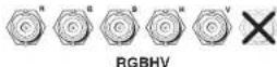
For RGBHV (separate H and V sync) output, connect the cables to five BNCs.
For RGBS (composite sync), connect the cables to four BNCs.
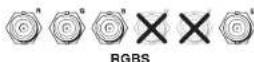
For RGsB (sync on green, SOG), connect the cables to three BNCs. Also select the SOG option on the front panel DIP switch (see item ⑥, Dip switches, in this chapter.

9 Stereo audio output connector (RGB 192 and 198 only) — Connect an audio device, such as powered speakers, to this 3.5 mm, 5-pole captive screw connector for balanced or unbalanced stereo or mono audio output. Stereo or mono output is determined by a DIP switch setting on the front panel. See DIP

The illustration here shows how to wire the captive screw audio connector. The connector is included with the interface, but
you must obtain the cable. Insert the wires into the appropriate openings in the captive screw connector. Tighten the screws on top to fasten the wires.
RGB 190F, RGB 192, and RGB 198 • Installation and Operation
Installation and Operation, cont'd
CAUTION
Wiring the audio incorrectly can damage the audio output circuits.
Connect the sleeve(s) to ground (GND).
Connecting the sleeve(s) to a negative (-) terminal will damage audio output circuits.

Unbalanced Output

Balanced Output
Figure 2-8 — Wiring the audio output connector
⑩ Unswitched AC outlets — These AC outlets are available in an Edison or Euro plug.
⑪ MAAP openings — Two double MAAP openings, one adjacent to the other, allow up to four single-sized MAAP pass through audio and video connectors.
⑫ Double AAP openings — This plate allows easy access to the back of the MAAPs while safely isolating the power supply and interface.
⑬ IEC AC power plug — Provides convenient power input.
Operation and Troubleshooting
Connect the power cords and turn on the displays (projectors or monitors), audio output devices (sound system - RGB 192 and 198 only), the interface and the input device (computer). The image should appear on screen, and sound should be audible (RGB 192 and 198 only). If not, ensure that all devices are plugged in and receiving power. Check the cabling and switch settings, and make adjustments as needed.
If the image does not appear or there is no sound
- Ensure that all devices are plugged in.
- Make sure that each device is receiving power. The interface's front panel LED lights green if the interface is receiving power and an active sync signal.
-
Check the cabling and the audio connector wiring and grounding, and make adjustments as needed.
-
For digital display devices (including LCD, DLP and plasma devices), try turning the DDSP DIP switch (switch 4) On (up) or Off (down) on the front panel.
- To test the system setup and output, substitute a video test generator for the computer input. Unplug the input and output devices' and the interface's power cords, replace the video source with a VTG, then reconnect power cords to restore AC power.
- Call the Extron S 3 Sales & Technical Support Hotline if needed.
If the image is not displayed correctly
- If the output image looks too green, the sync on green (SOG) DIP switch (switch 2) may be set to On (up), and the display device may not be configured to handle SOG signals. Set the switch to Off (down).
• If the picture bends or flags at the top of the screen, set the serration pulse DIP switch (switch 3) to Off (down). - For a display device that experiences intermittent glitches, try turning DDSP On (up) or Off (down) using DIP switch 1 on the front panel.
• If the picture hangs off the edge of the screen, adjust the Horizontal Shift control. - If the edges of the image seem to exceed their boundaries or if thin lines and sharp edges look thick and fuzzy, try changing the Level DIP switch (switch 1) to On (up). If the image is too bright, turn the Level switch to Off (down).
• If the image still does not display correctly, call the Extron S 3 Sales & Technical Support Hotline.
If the interface does not respond to controls
If the picture does not move on screen when the horizontal shift control is rotated, DDSP is in use. Set the DDSP DIP switch (switch 4) on the front panel to Off (down).
Installation and Operation, cont'd

RGB 190F, RGB 192, and 198
Appendix A
Reference Information
Specifications
Included Parts
Optional Accessories
Cables
Reference Information
Specifications
Video
Gain .... Unity (0.7 V), (0.8 V) 15% with 3 dB peaking
Bandwidth 300 MHz (-3 dB)
Max. rise/fall time 1.5 ns
Video input and loop-through
Number/signal type .... 1 analog VGA-UXGA, Mac, Sun RGBHV, RGBS, RGsB 1 buffered local monitor loop-through identical to the input
Connectors ....(1) female 15-pin HD (input) (1) female 15-pin HD (loop-through)
Nominal level 0.7 V p-p for RGB
Minimum/maximum levels ..... Analog: 0.3 V to 1.45 Vp-p with no offset at unity gain
Impedance 75 ohms
Horizontal frequency 15 kHz to 130 kHz
Vertical frequency 30 Hz to 170 Hz
Return loss .... <-41 dB @ 5 MHz
DC offset (max. allowable) ..... 4 V
Video output
Number/signal type ...... 1 RGBHV, RGBS, RGsB
Connectors 6 BNC female
Nominal level 0.7 Vp-p for RGB
Minimum/maximum levels ..... 0.7 V to 0.8 Vp-p (switch selectable) with peaking
Impedance 75 ohms
Return loss ...... -45 dB @ 5 MHz
DC offset .... ±5 mV with input at 0 offset
Sync
Input type ...... RGBHV, RGBS, RGsB (does not strip sync from video)
Output type ...... RGBHV at all times, RGBS at all times, RGsB (switch selectable)
Input level .... 2.0 V to 5.5 Vp-p with ±0.2 VDC offset (max.)
Output level 4.0 V to 5.0 Vp-p, unterminated
A-2
RGB 190F, RGB 192, and RGB 198 • Reference Information
Input impedance 510 ohms
Output impedance .... 75 ohms
Max. propagation delay .... 57 ns
Max. rise/fall time 4 ns
Polarity ...... RGBHV input: positive or negative
(follows input)
RGBS, RGsB input: negative
Audio — all models except RGB 190F
Gain .... Unbalanced output: 0 dB; balanced output: +6 dB
Frequency response 20 Hz to 20 kHz, ±0.05 dB
THD + Noise .... 0.03% @ 1 kHz, 0.3% @ 20 kHz at nominal level
S/N ....>90 dB at maximum output (14 dBm), balanced, unweighted
Crosstalk ....<-90 dB @ 1 kHz
Stereo channel separation ....>90 dB @ 1 kHz to 20 kHz
Audio input — all models except RGB 190F
Number/signal type .... 1 stereo or mono, unbalanced
Connectors ..... (1) 3.5 mm mini stereo audio jack (tip, ring, sleeve)
Impedance ....>10k ohms unbalanced, DC coupled
Nominal level -10 dBV (316 mVrms, -7.78 dBu)
Maximum level ....+9.5 dBu, (unbalanced) at 1% THD+N
NOTE
0 dBu = 0.775 Vrms, 0 dBV = 1 Vrms, 0 dBV ≈ 2 dBu
Audio output — all models except RGB 190F
Number/signal type .... 1 buffered stereo or mono, balanced/unbalanced
Connectors ..... (1) 3.5 mm captive screw connector, 5 pole
Impedance 50 ohms unbalanced, 100 ohms balanced
Gain error .... ±0.1 dB channel to channel
Maximum level (Hi-Z) ....>+14 dBm, balanced at 1% THD+N
Maximum level (600 ohm) ....> +9 dBm, balanced at 1% THD+N
General
Power (RGB 198, RGB 198EU) ... 100 VAC to 240 VAC, 50/60 Hz, 15 watts, internal, autoswitchable
RGB 190F, RGB 192, and RGB 198 • Reference Information
Reference Information, cont'd
External power supply (RGB 190F, RGB 192)
100 VAC to 240 VAC, 50/60 Hz, external,
autoswitchable; to 12 VDC, 1 A, regulated,
included
Power input requirements (RGB 190F, RGB 192)
12 VDC, 0.35 A
Temperature/humidity ...... Storage -40° to +158°F (-40° to +70°C) /
10% to 90%, noncondensing
Operating +32° to +122°F (0° to +50°C) /
10% to 90%, noncondensing
Rack mount
RGB 198, RGB 198EU ..... Yes, with optional 1U rack shelf,
part #60-190-01 or 60-604-01
Also furniture mountable with kit
70-077-01 (included) or kit #70-077-02
(optional)
RGB 190F, RGB 192 ...... No, but furniture mountable with
included under-desk mounting brackets
Enclosure type.... Metal
Enclosure dimensions
RGB 198, RGB 198EU ..... 1.75" H x 13.0" W x 4.5" D
(1U high, three quarters rack wide)
4.4 cm H x 32.7 cm W x 11.4 cm D
(Depth excludes connectors.)
RGB 190F, RGB 192 ..... 1.0" H x 5.7" W x 4.5" D
2.5 cm H x 14.5 cm W x 11.4 cm D
(Depth excludes connectors.)
Product weight
RGB 198, RGB 198EU ..... 2.0 lbs (0.9 kg)
RGB 190F, RGB 192 ..... 0.9 lbs (0.4 kg)
Shipping weight
RGB 198, RGB 198EU ..... 4 lbs (2 kg)
RGB 190F, RGB 192 ...... 3 lbs (2 kg)
Vibration ISTA 1A in carton
(International Safe Transit Association)
Listings UL, CUL
Compliances ...... CE, FCC Class A, VCCI, AS/NZS, ICES
MTBF 30,000 hours
Warranty 3 years parts and labor
NOTE All nominal levels are at ±10%.
NOTE Specifications are subject to change without notice.
A-4
RGB 190F, RGB 192, and RGB 198 • Reference Information
Included Parts
Unless otherwise noted, these items are included in each order for an RGB 190F, RGB 192, or RGB 198:
Interface Part number
RGB 190FV 60-486-61
VGA M 6' MHR (Molded) 26-238-01
RGB 190FM 60-486-62
Mac Adapter 15-HDM Kit with audio 70-156-01
RGB 190FS 60-486-63
13W3 Adapter 15-HDM Kit with audio 70-157-23
RGB 192V 60-486-01
VGAM 6' MHRA 15-pin HD Cable 26-490-02
RGB 192S 60-486-02
13W3 Adapter 15-HDM Kit with audio 70-157-03
RGB 198 60-673-02
RGB 198EU 60-674-02
Reference Information, cont'd
| Included items Part number |
| Rubber feet |
| IEC power cord |
| Twecker |
| Universal 12VDC external power supply(RGB 190 and RGB 192 only) 70-055-01 |
| Under-desk mounting kit instruction card 68-461-01 |
| 3.5 mm, 5-pole captive screw connector 10-319-10 |
| Under-desk mounting bracket kit 70-077-01 |
| 3/32 Hex wrench 100-012-01(RGB 198 only) |
| MAAP single blank (black) 70-315-11(RGB 198 only) |
| MAAP double blank (black) 70-315-12(RGB 198 only) |
| Two Cable Clamp/Pass-Through (Black) 70-127-01(RGB 198 only) |
| RGB 190F, RGB 192, and RGB 198 User's Manual |
Optional Accessories
| Accessory Part number | |
| Through-desk mounting bracket kit 70-077-02 | |
| 3.5 mm stereo plug 10-306-01 | |
| VGAM 3' MLIRA 15-pin HD cable 26-490-01 | |
| VGAM 6' MHRA 15-pin HD cable 26-490-02 | |
| VGAM 12' MHRA 15-pin HD cable 26-490-03 | |
| Mac Adapter 15-HDM Kit with audio | 70-156-01 |
| 13W3 Adapter 15-HDM Kit with audio | 70-157-01 |
| PS 100 12VDC, 2A Multi Unit Power Supply | 60-357-01 |
| Mini Architectural Adapter Plates (MAAP) (RGB 198 only) | assorted |
Cables
| BNC cable Part number | |
| BNC-5 Mini HR 3' | 26-260-15 |
| BNC-5 Mini HR 6' | 26-260-01 |
| BNC-5 Mini HR 12' | 26-260-02 |
| BNC-5 Mini HR 25' | 26-260-03 |
| BNC-5 Mini HR 50' | 26-260-04 |
| BNC-5 Mini HR 75' | 26-260-16 |
| BNC-5 Mini HR 100' 26-260-05 | |
| MHR-5P BNC 3' | 26-378-01 |
| MLR-5P BNC 6' | 26-378-02 |
| MHR-5P BNC 12' | 26-378-03 |
| MHR-5P BNC 25' | 26-378-04 |
| MHR-5P BNC 50' | 26-378-05 |
| MHR-5P BNC 75' | 26-378-06 |
| MHR-5P BNC 100' | 26-378-07 |
Reference Information, cont'd
A-8 RGB 190F, RGB 192, and RGB 198 • Reference Information
- EXTRON. ELECTRONICS INTERFACING, SWITCHING AND DISTRIBUTION
- PRECAUTIONS
- SAFETY INSTRUCTIONS • ENGLISH
- CAUTION
- AVERTISSEMENT
- EXTRON'S WARRANTY
- ASIA: JAPAN
- 安全须知 · 中文
- 1 CHAPTER ONE
- INTRODUCTION
- ABOUT THIS MANUAL
- ABOUT THE RGB 190F, RGB 192 AND RGB 198
- FEATURES
- INTRODUCTION, CONT'D
- CHAPTER TWO
- INSTALLATION AND OPERATION
- INSTALLATION OVERVIEW
- MOUNTING THE INTERFACES
- TABLETOP PLACEMENT
- UNDER-DESK MOUNTING
- THROUGH-DESK MOUNTING
- INSTALLATION AND OPERATION, CONT'D
- RACK MOUNTING (RGB 198 ONLY)
- CONNECTIONS AND SWITCHES
- 4—DDSP
- NOTE
- WARNING
- OPERATION AND TROUBLESHOOTING
- IF THE IMAGE DOES NOT APPEAR OR THERE IS NO SOUND
- IF THE IMAGE IS NOT DISPLAYED CORRECTLY
- IF THE INTERFACE DOES NOT RESPOND TO CONTROLS
- APPENDIX A
- REFERENCE INFORMATION
- SPECIFICATIONS
- VIDEO
- VIDEO INPUT AND LOOP-THROUGH
- VIDEO OUTPUT
- SYNC
- A-2
- AUDIO — ALL MODELS EXCEPT RGB 190F
- AUDIO INPUT — ALL MODELS EXCEPT RGB 190F
- AUDIO OUTPUT — ALL MODELS EXCEPT RGB 190F
- GENERAL
- REFERENCE INFORMATION, CONT'D
- 70-077-01 (INCLUDED) OR KIT #70-077-02
- INCLUDED PARTS
- OPTIONAL ACCESSORIES
Brand : Extron
Model : RGB 192V
Category : Audio/video converter