
CHV-RSS - Humidifier Crestron - Free user manual and instructions
Find the device manual for free CHV-RSS Crestron in PDF.


| Product Type | Humidifier |
| Brand | Crestron |
| Model | CHV-RSS |
| Dimensions (H x W x D) | 24 x 12 x 12 inches |
| Weight | 15 lbs |
| Power Supply | 120V AC, 60Hz |
| Power Consumption | 50W (max) |
| Humidification Capacity | Up to 500 sq ft |
| Water Tank Capacity | 2 gallons |
| Humidity Control | Adjustable, with digital display |
| Auto Shut-Off | When tank empty or target humidity reached |
| Filter Type | Wicking filter (replaceable) |
| Noise Level | Less than 30 dB |
| Smart Features | Compatible with Crestron home automation systems |
| Control Interface | Touch panel or Crestron remote |
| Maintenance | Clean tank weekly; replace filter every 3 months |
| Safety Features | Overheat protection, tip-over switch |
| Warranty | 2 years limited |
| Color | White or Black |
| Included Accessories | Filter, owner's manual |
Frequently Asked Questions - CHV-RSS Crestron
User questions about CHV-RSS Crestron
0 question about this device. Answer the ones you know or ask your own.
Ask a new question about this device
Download the instructions for your Humidifier in PDF format for free! Find your manual CHV-RSS - Crestron and take your electronic device back in hand. On this page are published all the documents necessary for the use of your device. CHV-RSS by Crestron.
USER MANUAL CHV-RSS Crestron
Remote Slab & Outdoor Temperature Sensor
Installation Guide
Regulatory Compliance
As of the date of manufacture, the CHV-RSS has been tested and found to comply with specifications for CE marking and standards per EMC and Radiocommunications Compliance Labelling.

Federal Communications Commission (FCC) Compliance Statement
CAUTION: Changes or modifications not expressly approved by the manufacturer responsible for compliance could void the user's authority to operate the equipment.
NOTE: This equipment has been tested and found to comply with the limits for a Class B digital device, pursuant to part 15 of the FCC Rules. These limits are designed to provide reasonable protection against harmful interference in a residential installation. This equipment generates, uses and can radiate radio frequency energy and, if not installed and used in accordance with the instructions, may cause harmful interference to radio communications. However, there is no guarantee that interference will not occur in a particular installation. If this equipment does cause harmful interference to radio or television reception, which can be determined by turning the equipment off and on, the user is encouraged to try to correct the interference by one or more of the following measures:
• Reorient or relocate the receiving antenna
- Increase the separation between the equipment and receiver
- Connect the equipment into an outlet on a circuit different from that to which the receiver is connected
- Consult the dealer or an experienced radio/TV technician for help
Industry Canada (IC) Compliance Statement
CAN ICES-3(B)/NMB-3(B)
The specific patents that cover Crestron products are listed at patents.crestron.com.
Crestron, the Crestron logo, and infiNET EX are either trademarks or registered trademarks of Crestron Electronics, Inc. in the United States and/or other countries. Other trademarks, registered trademarks and trade names may be used in this document to refer to either the entities claiming the marks and names or their products. Crestron disclaims any proprietary interest in the marks and names of others. Crestron is not responsible for errors in typography or photography.
This document was written by the Technical Publications department at Crestron.
©2013 Crestron Electronics, Inc.
Contents
Remote Slab Sensor and Outdoor Temperature Sensor: CHV-RSS 1
Introduction ...... 1
Specifications 2
Physical Description....3
Setup 4
Tile or Wood Floor Installation....4
Outdoor Installation....6
Hardware Hookup 8
Problem Solving 12
Troubleshooting....12
Reference Documents....12
Further Inquiries 12
Future Updates 13
Return and Warranty Policies....14
Merchandise Returns / Repair Service 14
Crestron Limited Warranty....14
Remote Slab Sensor and Outdoor Temperature Sensor: CHV-RSS
Introduction
The CHV-RSS is a remote temperature sensor designed for use with select Crestron ^® thermostats. Ideally suited for concrete slab, under floor, or any outdoor installation, the CHV-RSS is an extremely accurate temperature sensor potted within a rugged waterproof stainless steel sleeve. Using CAT5 or similar low capacitance wire, the remote sensor may be mounted up to 500 feet (153 meters) from the thermostat. One-piece mounting and a single non-polarized twisted-pair connection make the CHV-RSS simple to install. Up to four CHV-RSS sensors may be connected to a single CHV-THSTAT, CHV-TSTAT, CHV-STATEX or CHV-TSTATEX-FCU thermostat (all sold separately).
NOTE: When connecting a CHV-RSS sensor to a CHV-THSTAT or a CHV-TSTAT (models without infiNET EX ^® ), note the following firmware differences:
- Thermostat firmware version 1.xx supports two optional remote sensors. Thermostat firmware version 2.xx and later supports four optional remote sensor inputs, in any combination, for each thermostat.
- Firmware version 2.xx and later is required if the CHV-RSS is to be used as a slab temperature sensor. Any firmware version may be used to operate the CHV-RSS as an outdoor temperature sensor.
NOTE: If the maximum number of sensors is exceeded, some of the sensors will be ignored by the system.
Specifications
Specifications for the CHV-RSS are listed in the following table.
CHV-RSS Specifications
| SPECIFICATION DETAILS | |
| Measurement RangeIndoor TemperatureOutdoor TemperatureAccuracy ±1° F (0.5°C) | 0° to 110° F (-18° to 43°C)-40° to 170° F (-40° to 77°C) |
| Temperature AccuracyOver Full RangeAt Room Temperature | ±1° F (0.5°C)+1° F (+0.1 / -0.4°C) |
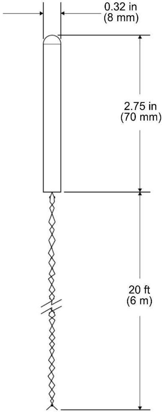
| Connection | 20 ft (6 m) twisted-pair pigtail;Non-polarized connection to remote sensor input of CHV-TSTAT, CHV-THSTAT,CHV-TSTATEX,CHV-TSTATEX-FCU;Maximum Cable Length:500 ft (153 m) via CAT5 |
| Enclosure Cylindrical Stainless | Steel |
| DimensionsDiameterDepth | 0.32 in (8 mm)2.75 in (70 mm) |
Physical Description
This section provides information on the connections, controls and indicators available on the CHV-RSS.
CHV-RSS Physical View
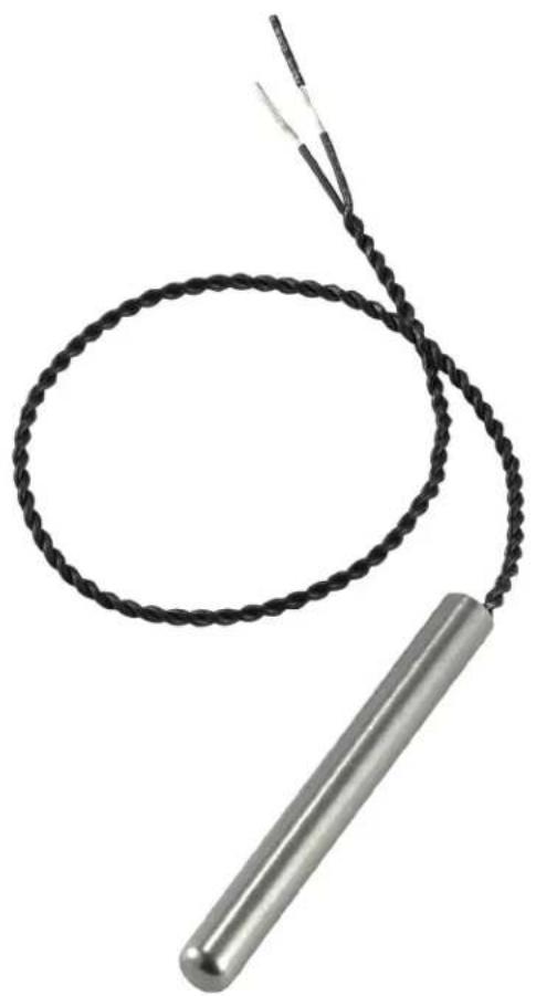
natural_image
Close-up of a coiled black wire with a metallic rod attached, no visible text or symbols.CHV-RSS Overall Dimensions
Setup
Tile or Wood Floor Installation
Crestron recommends the sensor be placed inside a 1/2 inch (13 mm) Electrical Metallic Tubing (EMT) conduit. This allows future sensor replacement, if required. The radius of the bend at the wall should be approximately 8 inches (203 mm), to allow for removal and replacement of the sensor.
Sensor Position (Side View)

NOTE: Ensure the sensor conduit is vertically centered in the slab below the surface.
Sensor Conduit Position in Slab

For indoor installations, consider the following:
• In small rooms, position the sensor near the center of the floor.
- In larger rooms, ensure the sensor is at least 6 feet (1.8 meters) from the wall.
- In very large spaces, two sensors may be used to average the floor temperature.
- The sensor should be placed midway between heating elements.
Sensor Position (Top View)

Tile Floor Mounting

NOTE: In tile floors, ensure a channel is made in the thin-set mortar, just above the subflooring, to properly position the sensor.
Outdoor Installation
Required Materials (not supplied):
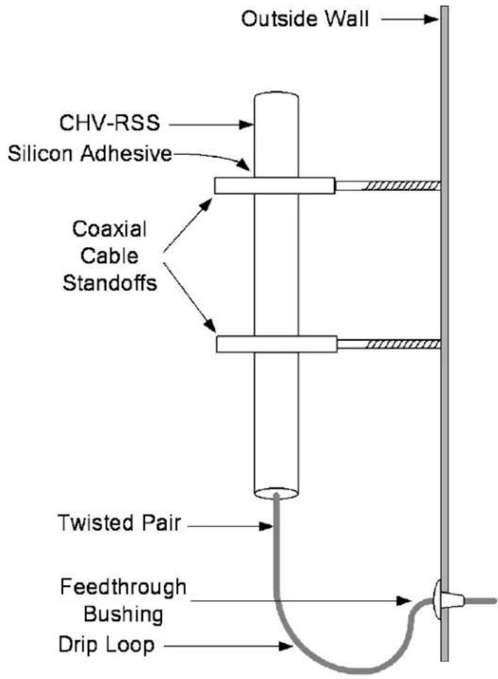
- Two wood screw coaxial cable standoffs with insulators
• One plastic feedthrough bushing - Silicon adhesive
NOTE: Mount in a location away from direct sunlight.
NOTE: Sensor should not come in contact with metal objects.
Complete the following procedure to install the CHV-RSS:
- Mount the sensor using two coaxial cable standoffs. If the fit is not snug, use silicon adhesive to secure the sensor in place.
- Use a plastic feedthrough bushing and pass the wires through the outside wall.
- Form a drip loop in the wire to prevent moisture from entering the building.
Outside Wall Mounting


Hardware Hookup
CHV-RSS sensors connect to the terminal blocks on the back plate of the CHV-TSTAT, CHV-THSTAT, CHV-TSTATEX, CHV-TSTATEX-FCU thermostats (all sold separately).
NOTE: Sensor wiring is non-polarized.
NOTE: Up to two CHV-RSS sensors may be connected to a single channel.
NOTE: Use a separate run of wire for each sensor.
NOTE: Wire runs should be low capacitance twisted pair wire such as CAT3 (up to 250 feet (76 meters)), CAT5 (up to 500 feet (152 meters)), or similar low capacitance (less than 7000 pF) wire.
NOTE: Sensor lines should not be run parallel to any other wiring. Lines should cross other cables at right angles.
Complete the following procedure to connect the CHV-RSS to the system:
- Turn off the circuit breaker.
CAUTION: Do not press on the LCD display of the thermostat during this procedure, as this may cause the screen to crack.
- Separate thermostat front plate from back plate (it may be necessary to exert force when removing the faceplate.)
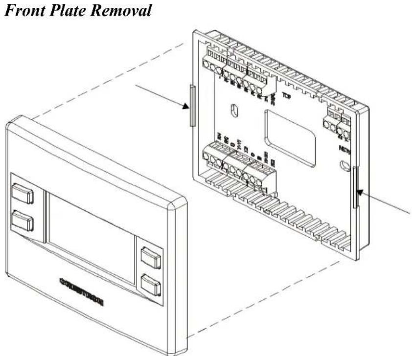
- To connect the sensor(s) to a single channel on the thermostat, wire the CHV-RSS to the RS1 and RSR terminals as shown on the following page.
CHV-RSS (Single Channel) Hookup (Two Sensors Shown)
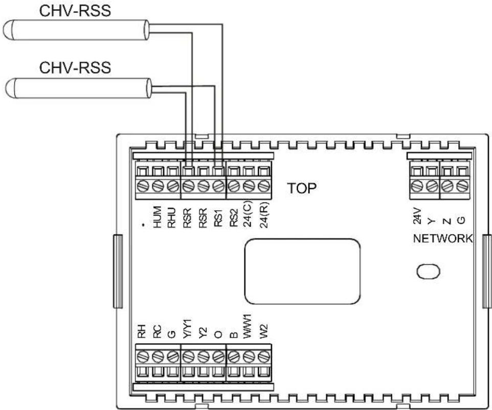
- To connect sensors using two channels on the thermostat, wire up to two devices to the RS1 and RSR terminals, and up to two devices to the RS2 and RSR terminals as shown in the illustration on the following page.
CHV-RSS (Dual Channel) Hookup (Four Sensors Shown)

- Note the orientation of the front plate connection pins and reattach the front plate (make sure the front plate snaps in place and no wires are pinched).
For additional information about the thermostat connections, refer to the latest version of the CHV-TSTAT and CHV-THSTAT Thermostats Operations and Installation Guide (Doc. 8163), the CHV-TSTATEX Thermostat Operations and Installation Guide (Doc. 6989) or the CHV-TSTATEX-FCU Thermostat Operations and Installation Guide (Doc. 7206). They are available from the Creston Web site (www.crestron.com/manuals).
Problem Solving
Troubleshooting
The following table provides corrective action for possible trouble situations. If further assistance is required, please contact a Crestron customer service representative.
CHV-RSS Troubleshooting
| TROUBLE | POSSIBLE CAUSE(S) | CORRECTIVE ACTION |
| No signal. Improper connection. | Check connection to thermostat (refer to “Hardware Hookup”, which starts on page 8). | |
| Incomplete (open) circuit. | ||
Reference Documents
The latest version of all documents mentioned within the guide can be obtained from the Crestron Web site (www.crestron.com/manuals).
List of Related Reference Documents
| DOCUMENT TITLE |
| CHV-TSTAT & CHV-THSTAT Thermostats |
| CHV-TSTATEX Thermostat |
| CHV-TSTATEX-FCU Thermostat |
Further Inquiries
To locate specific information or to resolve questions after reviewing this guide, contact Crestron's True Blue Support at 1-888-CRESTRON [1-888-273-7876] or refer to the listing of Crestron worldwide offices on the Crestron Web site (www.crestron.com/offices) for assistance within a particular geographic region.
To post a question about Crestron products, log onto the Online Help section of the Crestron Web site (www.crestron.com/onlinehelp). First-time users must establish a user account to fully benefit from all available features.
Future Updates
As Crestron improves functions, adds new features and extends the capabilities of the CHV-RSS, additional information may be made available as manual updates. These updates are solely electronic and serve as intermediary supplements prior to the release of a complete technical documentation revision.
Check the Crestron Web site periodically for manual update availability and its relevance. Updates are identified as an “Addendum” in the Download column.
Return and Warranty Policies
Merchandise Returns / Repair Service
- No merchandise may be returned for credit, exchange or service without prior authorization from Crestron. To obtain warranty service for Crestron products, contact an authorized Crestron dealer. Only authorized Crestron dealers may contact the factory and request an RMA (Return Merchandise Authorization) number. Enclose a note specifying the nature of the problem, name and phone number of contact person, RMA number and return address.
- Products may be returned for credit, exchange or service with a Crestron Return Merchandise Authorization (RMA) number. Authorized returns must be shipped freight prepaid to Crestron, 6 Volvo Drive, Rockleigh, N.J. or its authorized subsidiaries, with RMA number clearly marked on the outside of all cartons. Shipments arriving freight collect or without an RMA number shall be subject to refusal. Crestron reserves the right in its sole and absolute discretion to charge a 15% restocking fee plus shipping costs on any products returned with an RMA.
- Return freight charges following repair of items under warranty shall be paid by Crestron, shipping by standard ground carrier. In the event repairs are found to be non-warranty, return freight costs shall be paid by the purchaser.
Crestron Limited Warranty
Crestron Electronics, Inc. warrants its products to be free from manufacturing defects in materials and workmanship under normal use for a period of three (3) years from the date of purchase from Crestron, with the following exceptions: disk drives and any other moving or rotating mechanical parts, pan/tilt heads and power supplies are covered for a period of one (1) year; touch screen display and overlay components are covered for 90 days; batteries and incandescent lamps are not covered.
This warranty extends to products purchased directly from Crestron or an authorized Crestron dealer. Purchasers should inquire of the dealer regarding the nature and extent of the dealer's warranty, if any.
Crestron shall not be liable to honor the terms of this warranty if the product has been used in any application other than that for which it was intended or if it has been subjected to misuse, accidental damage, modification or improper installation procedures. Furthermore, this warranty does not cover any product that has had the serial number altered, defaced or removed.
This warranty shall be the sole and exclusive remedy to the original purchaser. In no event shall Crestron be liable for incidental or consequential damages of any kind (property or economic damages inclusive) arising from the sale or use of this equipment. Crestron is not liable for any claim made by a third party or made by the purchaser for a third party.
Crestron shall, at its option, repair or replace any product found defective, without charge for parts or labor. Repaired or replaced equipment and parts supplied under this warranty shall be covered only by the unexpired portion of the warranty.
Except as expressly set forth in this warranty, Crestron makes no other warranties, expressed or implied, nor authorizes any other party to offer any warranty, including any implied warranties of merchantability or fitness for a particular purpose. Any implied warranties that may be imposed by law are limited to the terms of this limited warranty. This warranty statement supersedes all previous warranties.
This page is intentionally left blank.

CRESTRON®
Crestron Electronics, Inc.
15 Volvo Drive Rockleigh, NJ 07647
Tel: 888.CRESTRON 02.13
Fax: 201.767.7576 Specifications subject to
www.crestron.com

Installation Guide - DOC. 6229D
(2009402)
change without notice.
- Remote Slab & Outdoor Temperature Sensor
- Regulatory Compliance
- Federal Communications Commission (FCC) Compliance Statement
- Contents
- Remote Slab Sensor and Outdoor Temperature Sensor: CHV-RSS 1
- Remote Slab Sensor and Outdoor Temperature Sensor: CHV-RSS
- Introduction
- Specifications
- Physical Description
- Setup
- Tile or Wood Floor Installation
- Outdoor Installation
- Hardware Hookup
- Problem Solving
- Troubleshooting
- Reference Documents
- Further Inquiries
- Future Updates
- Return and Warranty Policies
- Merchandise Returns / Repair Service
- Crestron Limited Warranty
- CRESTRON®
Brand : Crestron
Model : CHV-RSS
Category : Humidifier