
BVB4 - Beer dispenser CDA - Free user manual and instructions
Find the device manual for free BVB4 CDA in PDF.


| Product Type | Beer Dispenser |
| Brand | CDA |
| Model | BVB4 |
| Dimensions (W x D x H) | Approx. 30 x 40 x 40 cm |
| Weight | Approx. 6 kg |
| Power Supply | 220-240 V, 50/60 Hz |
| Power Consumption | Approx. 80 W |
| Cooling System | Compressor-based cooling |
| Beer Capacity | Compatible with standard 5L kegs and mini kegs |
| Dispensing System | Pressure tap with adjustable flow |
| CO2 Usage | Requires external CO2 cylinder (not included) |
| Temperature Range | 2 - 8 °C |
| Foam Control | Adjustable tap for optimal foam |
| Cleaning | Removable drip tray and tap for easy cleaning |
| Safety Features | Overpressure valve, stable feet |
| Spare Parts | Available: tap, drip tray, gaskets, CO2 regulator |
| Repairability | Modular design for easy replacement of parts |
| Noise Level | Approx. 40 dB |
| User Manual | Free download in PDF (9 pages) |
Frequently Asked Questions - BVB4 CDA
User questions about BVB4 CDA
0 question about this device. Answer the ones you know or ask your own.
Ask a new question about this device
Download the instructions for your Beer dispenser in PDF format for free! Find your manual BVB4 - CDA and take your electronic device back in hand. On this page are published all the documents necessary for the use of your device. BVB4 by CDA.
USER MANUAL BVB4 CDA
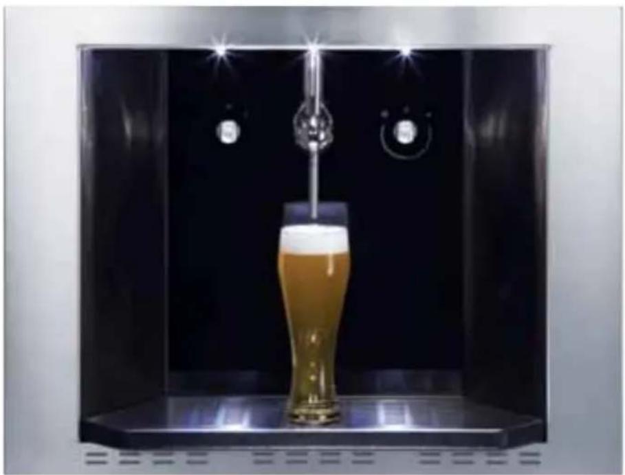
BVB4 Draught Beer Dispenser
Manual for Installation, Use and Maintenance
C|D|A|
natural_image
Water dispenser pouring beer into a glass (no text or symbols visible)

Beermachine (afb./fig. 1)
EN
A - ON/OFF switch
B - Beer tap
C - Beer temperature thermostat
D - Lighting
E - Grid
F - Beer drip tray
G - Insulated beer line
H - Beer fitting
I - Dispense head
J - Beer keg (not supplied)
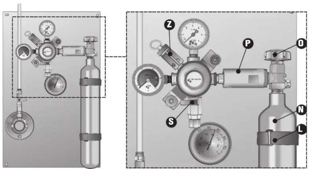
K - CO2fitting
L - Cylinder strap
M - CO ^2 line
N - CO ^2 cylinder
0 - CO ^2 cylinder tap
P - CO ^2 high pressure attachment, with hand clamp device
Q - Beer pressure gauge
R - CO ^2 pressure regulator screw
S - CO ^2 outlet tap
T - Thermometer
U - CO ^2 cylinder pressure gauge
V - Washing attachment
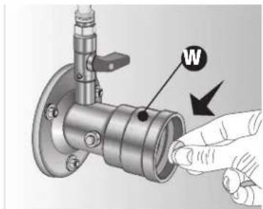
W - Tab compartment
X - Water tap for washing
Y - Mains water line
Z - Mains water outlet tap
1 - Relief valve
2 - Cleaning tabs
3 - Screws and washers
NL
A - Interruptor general on/off
- SUPPLIED ITEMS - Page 5
- TECHNICAL SPECIFICATIONS - Page 5
- SAFETY AND INSTRUCTIONS - Page 5
- DISPOSAL OF HOUSEHOLD APPLIANCES - Page 6
- INSTALLING THE APPLIANCE - Page 6
- CONNECTING AND REPLACING THE CO ^2 CYLINDER - Page 7
- REGULATING CO ^2 , TEMPERATURE AND SERVING BEER - Page 7
- MAINTENANCE AND CLEANING - Page 8
- REPLACING THE KEG
- Page 11
1. SUPPLIED ITEMS
• CLEANING TABS 1 PACK OF 10 TABS
• 4.5 x 35 SCREWS NR. 04
• 4.5 x 18 SCREWS NR. 02
• WASHERS NR. 04
• INSTRUCTIONS BOOKLET NR. 01
• WASHING ATTACHMENT FOR SANKEY (S-SYSTEM) NR. 01
• DISPENSE HEAD FOR SANKEY (S-SYSTEM) NR. 01
2. TECHNICAL SPECIFICATIONS
Operating voltage : 230 V-AC 50 Hz
Absorbed power : 190 Watt
Draught capacity: +/- 40 l/H (depends on the set pressure)
Cooling capacity: 465W/ 400 kcal/h
Sizes:
External: W 595 x H 458 x D 19
Internal: W 560 x H 450 x D 400
3. SAFETY AND INSTRUCTIONS
This dispenser conforms to current safety regulations. Improper use of the dispenser may cause damage to people and/or objects. Carefully read the instructions for use before operating the dispenser.
The instructions include important information on safety, use and maintenance to protect you and the machine. The dispenser has been exclusively designed for serving beer. Any other use is not permitted and may be hazardous.
C D A shall not be held liable in any way for damage caused to people or objects as a result of improper and/or incorrect use of the dispenser.
TECHNICAL SAFETY
Before connecting the dispenser to the mains, make sure the voltage and frequency on the rating plate are compatible with the electrical system.
The safety of the dispenser is only guaranteed if it is connected to a standard earthing conductor.
C D A shall not be held liable in any way for damage caused to people or objects as a result of faulty operation of the earthing conductor (for example the risk of electric shock).
Do not use extension leads to connect the dispenser. Extension leads do not guarantee safety conditions required for the dispenser (for example the risk of overheating).
If the mains lead connecting the dispenser is damaged, it must be replaced by qualified personnel, to prevent any risks.
To prevent considerable harm to the user, installation, maintenance and repairs must be undertaken exclusively by qualified personnel.
To disconnect the dispenser from the mains, remove the plug from the socket without pulling the lead.
Do not open the dispenser cover, under any circumstances. Do not touch live electrical parts or leads and do not change the electrical structure of the dispenser, as this may result in electric shock.
The cylinder contains high pressure CO ^2 gas, pressurised to approximately 230 bar. Handle the cylinder with the utmost care and always close tap “O” (fig. 1) even when the cylinder is empty. This tap should be kept closed, even when the machine is not used.
C D A shall not be held liable in any way for damage caused to people or objects as a result of failure to comply with the above.
4. DISPOSAL OF HOUSEHOLD APPLIANCES
Under the European directive 2002/96/EC on waste from electrical and electronic equipment (WEEE),
household appliances may not be disposed of at normal landfill sites. Old appliances must be collected separately to optimise the recovery and recycling of their materials and to prevent potential harm to health and the environment. The symbol of a bin with a cross is affixed on all products, to remind users that they must dispose of the product separately. For further information on how to dispose of household appliances, users should contact a public authority or their dealers.

his appliance has been manufactured in compliance with EN 60204 - 1 ; and conforms to the
tives: -98/37/EG -89/336/EWG EMV -73/23/EWG
5. INSTALLING THE APPLIANCE

Make sure the beer dispenser can fi t into the cabinet (fi g 2).
-
Drill a ∅ 5 cm hole at the back of the cabinet base (fi g. 2) to pass the beer flow line through (fi g. 2).
-
Position the dispenser, after connecting the mains lead and passing the beer flow line "G" (fig. 2) through the cabinet base (where the keg is stored) (fig 2).
-
Secure the dispenser to the base using the 2 screws provided, inserted in the two holes in the drip tray storage area.
-
Fit the tray and rack
-
Fit the control unit on the side of the cabinet, placing it against the base and secure with the 4 screws provided (fig. 2).
-
Insert the adaptor (same type as the dispense head) in the washing attachment.
-
Carefully connect fitting "H" (fig. 1), positioned at the end of the beer flow line "G" (fig. 1) to the beer outlet connection of the dispense head "I" (fig. 1).
-
Carefully connect fitting "K" (fig. 1), positioned at the end of the CO^2 flow line "M" (fig. 1) to the CO^2 inlet connection of the dispense head "I" (fig. 1).
-
Fit the dispense head on the keg attachment and secure lowering the dispense head lever and making sure it is fitted properly to avoid beer and CO ^2 leaks. Click to secure.
Always check with your keg retailer which system is compatible with the keg you require (Sankey S-System, Grundy G-System).
6. CONNECTING AND REPLACING THE CO ^2 CYLINDER
CAUTION: The cylinder contains high pressure CO ^2 gas, pressurised to approximately 230 bar.
Handle the cylinder with the utmost care and always close tap "O" (fig. 1) even when the cylinder is empty. Taps "O" and "S" (fig. 1) should be kept closed, even when the machine is not used.
Do not open the cylinder tap (valve) until all items, including the dispense head "I" (fi g. 1) have been connected.
To connect the CO ^2 cylinder, proceed as follows:
- Close tap "S" (fi g. 3).
- Remove the seal from the cylinder.
- Fit the CO ^2 outlet nozzle of the cylinder to the attachment with the reducer manual clamp.
- Tighten carefully, screwing down the manual clamp device until it is firmly secured.
- Tighten the cylinder straps "L" (fi g. 3).
- Open tap "O" (valve) (fi g. 3).
- Open tap "S" (fi g. 3).
To remove the empty cylinder, proceed as follow:
- Close tap "O" (valve) (fi g. 3).
- Close tap "S" (fi g. 3).
- Release the cylinder straps "L" (fi g. 3).
- Loosen the manual clamp device until the cylinder is completely released.
(Fig. 3)
7. REGULATING CO ^2 , TEMPERATURE AND SERVING BEER
Important: Beer is not a drink for children. Children should only have access to the dispenser under the strict supervision of their parents or responsible adults.
If children are at home alone, close taps "O" and "S" (fi g. 1) and remove the dispense head "I" (fi g. 1) from the keg.
Beer will keep for approximately 8 days after a new keg has been opened. However this can differ per brand and type of beer. Check for accurate durability after opening the keg with your keg supplier.
Beer quickly deteriorates, posing a hazard (bacteria develop), so the dispenser should be washed and disinfected regularly. This should preferably be done every time the keg is changed or at least every 15 days.
A dispenser with stale beer residues can smell unpleasant and give the beer an unpleasant taste. The beer in a new keg, connected to a dirty dispenser, is quickly contaminated if bacteria are present, and even if a new keg is connected, the beer acquires an unpleasant taste. Carefully follow the instructions for “washing and disinfecting the dispenser”.
C D A shall not be held liable in any way for damage caused to people or objects as a result of failure to comply with the above.
REGULATING CO ^2 PRESSURE
Caution: Do not disassemble or tamper with the pressure reducer.
The high pressure of CO^2 is lowered to a set value using the adjusting screw “R” (fi g. 1) on the pressure reducer.
The pressure value is configured based on the temperature that the keg and type of beer (Pils or Lager) is exposed to.
The wrong pressure regulation will make the beer too frothy or under carbonated (dull beer or with little froth).
N.B. If the pressure is too low for the keg temperature, the beer will be served very frothy. To regulate pressure, see the values in the table (table 1).
The table (tab. 1) shows the pressure to use.
- Open taps "S" and "O" (fi g. 1).
• Make sure all fittings and connections are properly sealed and that there are no CO ^2 leaks. If there are leaks, close taps “O” and “S” (fig. 1) and check the cause of the leak. - Read and take note of the temperature on the thermometer "T" (fi g. 1).
- Check the pressure to select, from the table.
- The pressure is indicated by the hand on the pressure gauge "Q" (fi g. 1).
• Turn the adjusting screw clockwise or anticlockwise until the hand on the pressure gauge "Q" (fig. 1) is on the selected value. - Secure the adjusting screw using the lock nut below the screw.
N.B. The pressure gauge "U" (fig. 1) indicates cylinder pressure. When the hand (with the tap "O" (fig. 1) open) drops to the red zone, the cylinder is empty. A full cylinder will serve approximately 50 litres of beer.
To replace, see chapter CONNECTING AND REPLACING THE CO ^2 CYLINDER
(table 1)
The dispenser can serve beer at a temperature from approximately 4^ C to 8^ C. This value is affected by the temperature of the keg, which must not be stored at a temperature above 25^ C. If the temperature is higher than 25^ C, the dispenser cannot serve beer properly (too much froth and beer flowing unevenly).
- Turn knob "C" (fig. 1) clockwise to lower the temperature, or anticlockwise to increase the temperature. Turn the knob to the desired temperature and keep in position, even when the machine is turned off.
SERVING BEER
As the dispenser consumes little energy, we recommend leaving it turned on. The beer in the circuits will not heat up and will not deteriorate. Besides an unpleasant taste, bacteria harmful to health could grow.
- Turn on the dispenser and the lighting, turning knob "A" (figure 1) to position "I".
• After around 5 minutes, the dispenser is ready to serve beer at temperature from approximately 4°C to 8°C.
! We recommend rinsing glasses with cold water (draining them rather than drying them), before serving the beer. This will cool the beer and maintain its serving temperature for longer.
Serving beer:
• Pull the tap entirely towards you, quickly and firmly. Be sure not to keep the tap halfway open, for this way only froth will come out of the tap.
- As soon as you see the beer flowing out of the tap, put the glass underneath and tilt.
• This needs a little practice, as it should be done quickly.
- Gradually straighten the glass while it is being filled, until it is nearly in an upright position.
N.B. If you want a froth "decoration" or extra froth, move the tap very slightly towards you, so only froth will come out.
Important: When the dispenser is not in use, it must be washed and disinfected (see the next chapter "WASHING AND DISINFECTING THE DISPENSER") and the circuits emptied. Open the tap handle and drain the water left in the circuits from the dispense head, after removing it from the key.
8. MAINTENANCE AND CLEANING
WASHING AND DISINFECTING THE DISPENSER
Use the tabs provided and carefully read the instructions below.
Alkaline product for the chemical and mechanical disinfection and cleaning of beer dispensers, conforming to TRSK 501 requirements.
Contents: Dichloroisocyanurate below 5 %, phosphonates, sodium carbonate, sodium citrate, auxiliary agents.
Safety instructions:
Do not use in conjunction with other products (acids and cleaning products containing acids) to avoid the risk of harmful vapours (chlorine gases) forming. Harmful if ingested.
Irritating to eyes and the respiratory system. Keep out of reach of children.
In case of contact with eyes, rinse immediately with plenty of water and seek medical advice.
Toxic for aquatic organisms, may cause long-term adverse effects in the aquatic environment.
Store in a dry place.
Beer will keep for approximately 8 days after a new keg has been opened. However this can differ per brand and type of beer. Check for accurate durability after opening the keg with your keg supplier.
Beer quickly deteriorates, posing a hazard (harmful bacteria develop), so the dispenser should be washed and disinfected regularly. This should preferably be done every time the keg is changed or at least every 15 days.
A dispenser with stale beer residues can smell unpleasant and give the beer an unpleasant taste.
The beer in a new keg, connected to a dirty dispenser, is quickly contaminated if bacteria are present, and even if a new keg is connected, the beer acquires an unpleasant taste.
Wash the dispenser as follows:
(fi
g.
4)

(fi g. 5)
natural_image
Mechanical assembly diagram showing a valve with a hand pointing to a component labeled 'W' (no text or symbols beyond the label)- Insert the cleaning tab compartment W (Fig. 5) in the washing attachment V (Fig. 4).
- Put a tab (carefully read the instructions) in compartment "W" (fig. 5) of the washing attachment "V" (fig 4). This will dissolve on contact with water turning it light blue.
(fi
g.
6)
(fi g. 7)

natural_image
Close-up of a gas pressure regulator with valve and tubing (no visible text or symbols)
- Close tap "O" (fi g. 6) and "S" (fi g. 1)
- Pull the lever of the relief valve "Z" (fi g. 7) until all CO ^2 left in the keg and lines has come out.
(fi
g.
8)
(fi g. 9)

natural_image
Mechanical assembly diagram showing a valve inserted into a cylindrical tank with a downward arrow indicating motion (no text or symbols present)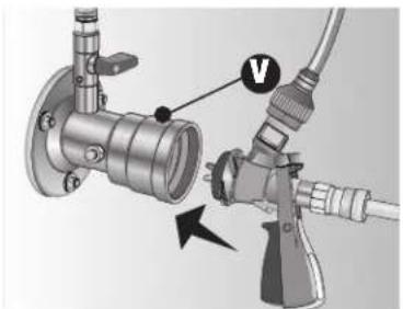
natural_image
Mechanical assembly diagram showing pipe connection with valve and connector (no text or symbols)- Release the dispense head using the lever (fi g. 8).
- Fit and secure the dispense head to the washing attachment "V" (fi g. 9).
natural_image
Diagram of a mechanical device with labeled parts (fi, g, 10), showing internal components and flow paths (no readable text or symbols)
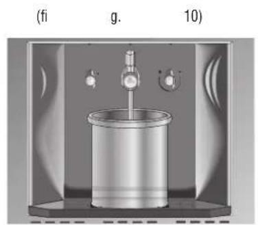
- Put a container below the beer tap "B" (fig. 10) or connect an adequate tube to the beer tap in order that the cleaning product goes out directly in the container or sink.
• Fully open the beer tap "B" (fi g. 11)


- Open the water tap "Z" (fi g. 12).
- Open tap "X" (fig. 13). The water should flow slowly from the beer tap. If the water pressure is too high, adjust tap "X" (fig. 13) or "Z" (fig 12).
• As soon as blue water starts to flow out of the beer tap, close the tap and leave the product to work for a minimum of 15 minutes.
• After 15 minutes open the tap and let the water flow until it is clear. Keep open for a few more minutes to thoroughly rinse.
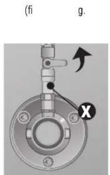


- Close taps "X", "Z" and "B" (fi g. 14).
(fi g. 15) (fi g. 16)

natural_image
Mechanical assembly diagram showing a pipe fitting connected to a hose with a valve, no text or symbols present
natural_image
Mechanical assembly diagram showing a valve inserted into a cylindrical tank with a downward arrow indicating motion (no text or symbols present)- Release and remove the dispense head from the washing attachment "V" (fi g. 15).
- Carefully attach the dispense head to the keg attachment and secure with the lever (fi g. 16).
(fi g. 17)
natural_image
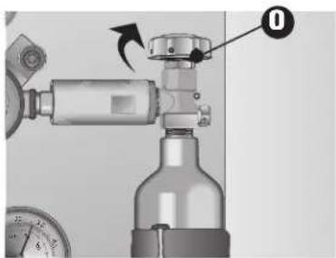
Mechanical device with valve and pressure gauge, no visible text or symbols- Open taps "O" (fi g. 17) en "S" (fi g. 1).
- The machine is now ready for use and sanitised, and will keep all the original taste of the beer intact.
CLEANING AND CARING FOR THE DISPENSER
Regularly cleaning the dispenser will guarantee it works properly and ensure a long life. Remove the rack and drip tray from the dispenser and clean steel parts with a suitable, gentle, commercial cleaning product. Do not under any circumstances use harsh, abrasive cleaning products.
The drip tray and rack should be emptied and washed daily to avoid beer drying up, which is hard to remove, leaving a bad, unpleasant smell.
C D A shall not be held liable in any way for damage caused to people or objects as a result of failure to comply with the above.
9. REPLACING THE KEG
- Close tap "O" and "S" (fi g. 1).
- Pull the lever of the CO ^2 relief valve "1" (fi g. 1) until all the CO ^2 left in the keg and lines has come out.
(fi g. 18)
natural_image
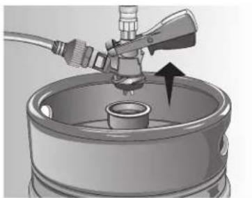
Mechanical assembly diagram showing a valve inserted into a cylindrical tank with a downward arrow indicating motion (no text or symbols present)- Release the dispense head using the lever (fi g. 18).
- Position the full keg and attach the dispense head to the keg attachment and secure with the lever.
- Open tap "O" and "S" (fig. 1).
- Open the beer tap "B" (fi g. 1) and let the froth flow out until the beer comes out at an even, constant flow rate.
• The machine is now ready for use.
- BVB4 Draught Beer Dispenser
- Manual for Installation, Use and Maintenance
- C|D|A|
- EN
- NL
- SUPPLIED ITEMS
- TECHNICAL SPECIFICATIONS
- SAFETY AND INSTRUCTIONS
- TECHNICAL SAFETY
- DISPOSAL OF HOUSEHOLD APPLIANCES
- INSTALLING THE APPLIANCE
- CONNECTING AND REPLACING THE CO 2 CYLINDER
- To connect the CO 2 cylinder, proceed as follows:
- To remove the empty cylinder, proceed as follow:
- REGULATING CO 2 , TEMPERATURE AND SERVING BEER
- REGULATING CO 2 PRESSURE
- SERVING BEER
- Serving beer:
- MAINTENANCE AND CLEANING
- Safety instructions:
- Wash the dispenser as follows:
- CLEANING AND CARING FOR THE DISPENSER
- REPLACING THE KEG
Brand : CDA
Model : BVB4
Category : Beer dispenser