
DIY 15" Gaming Notebook - Laptop OCZ Technology - Free user manual and instructions
Find the device manual for free DIY 15" Gaming Notebook OCZ Technology in PDF.


| Product Type | Gaming Laptop |
| Model | DIY 15" Gaming Notebook |
| Brand | OCZ Technology |
| Display Size | 15.6 inches |
| Display Resolution | 1920 x 1080 pixels |
| Processor | Intel Core i7 (4th Gen) |
| RAM | 16 GB DDR3 |
| Storage | 256 GB SSD + 1 TB HDD |
| Graphics | NVIDIA GeForce GTX 860M |
| Operating System | Windows 10 (64-bit) |
| Weight | 2.5 kg (5.5 lbs) |
| Dimensions (W x D x H) | 380 x 260 x 28 mm |
| Battery | 6-cell Li-Ion, 48 Wh |
| Power Adapter | 120W AC adapter |
| Ports | USB 3.0 (x3), HDMI, Ethernet, Audio |
| Connectivity | Wi-Fi 802.11ac, Bluetooth 4.0 |
| Keyboard | Backlit chiclet keyboard |
| Cooling System | Dual fan with heat pipes |
| Cleaning Instructions | Use a soft, dry cloth; avoid liquids |
| Safety Information | Do not block vents; avoid extreme temperatures |
| Spare Parts / Repairability | Upgradeable RAM, SSD, HDD, battery |
| Warranty | 1 year limited warranty |
Frequently Asked Questions - DIY 15" Gaming Notebook OCZ Technology
User questions about DIY 15" Gaming Notebook OCZ Technology
0 question about this device. Answer the ones you know or ask your own.
Ask a new question about this device
Download the instructions for your Laptop in PDF format for free! Find your manual DIY 15" Gaming Notebook - OCZ Technology and take your electronic device back in hand. On this page are published all the documents necessary for the use of your device. DIY 15" Gaming Notebook by OCZ Technology.
USER MANUAL DIY 15" Gaming Notebook OCZ Technology

SETUP GUIDE
Model: OCZDIY15A2 Series
DIY Notebook Quick Installation Guide
Carefully remove the notebook from the bag. Use the protective sleeve as a pad and place the notebook on it during the configuration process.

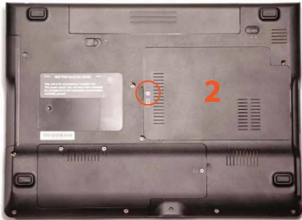
Familiarize yourself with the notebook before opening it up and exposing the inside to dust and other environmental factors. The picture below shows the location of all important components behind removable access panels, all other screws need not and should not be opened! There are two major panels on the notebook: The hard disk drive is under panel (1). The memory expansion slots and the processor socket are under panel (2).

Installing/Replacing Hard Drive
Remove the three screws securing the cover in place:

Carefully lift the cover as shown:

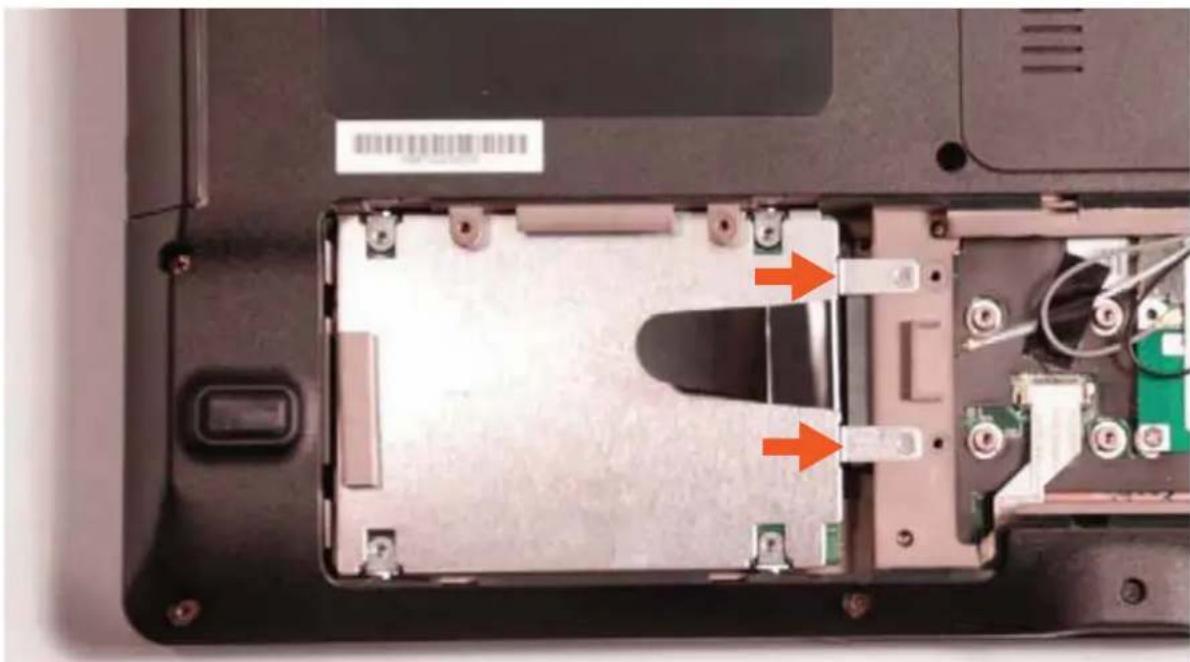
This will reveal one hard disk drive bay with included mounting bracket. Remove the two screws securing the mounting bracket. Note the SATA connectors that will only match with HDDs and SSDs conforming to the SATA standard.

Identify the HDD mounting bracket including four short screws
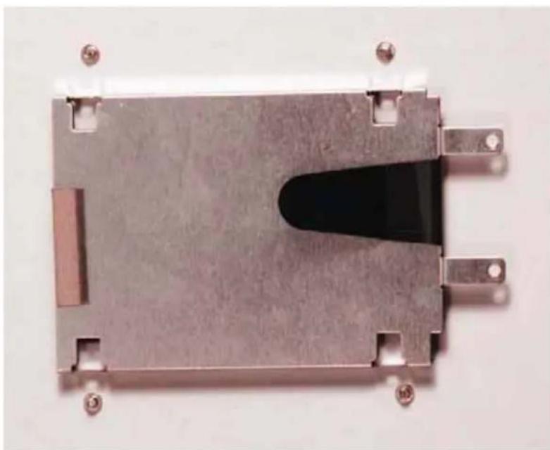
Place the mounting bracket upside down. Place the hard drive and make sure the hard drive connector faces in the direction of the arrows as shown in the picture. Align the mounting bracket with the hard drive screw holes at the side and secure it all with the four short screws.

Insert the HDD into the drive bay and engage the edge connector in the SATA socket. Align the two screw holes and fasten them tightly.
Fasten the cover with the three appropriate screws.
Installing/Replacing The Memory:
Please remove cover (2) after removing the necessary screw.
This will expose the motherboard with the memory slots (arrow):

Insert your DDR3 SODIMMs into the vacant slots at approximately 45° angle as shown below. Note that the memory must be fully inserted into the slots.
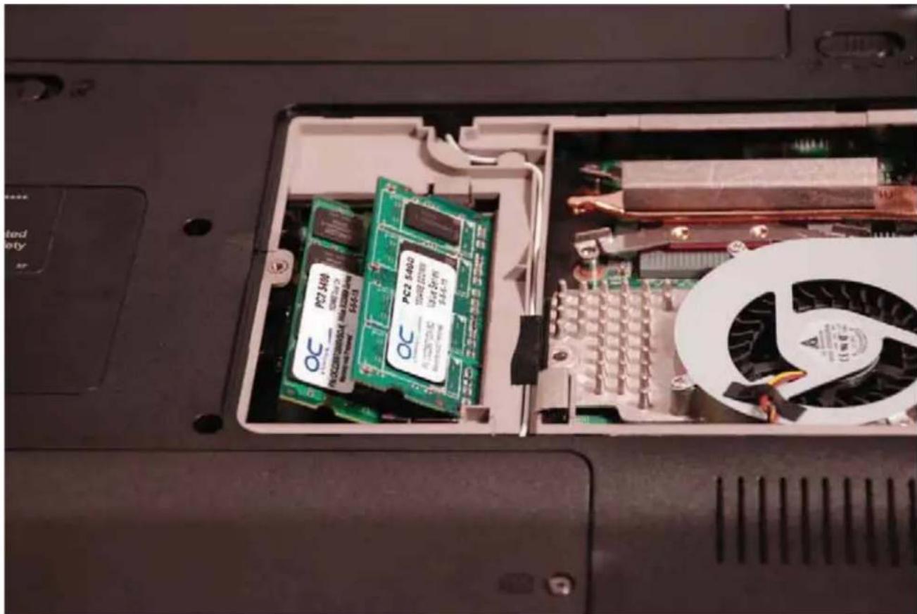
Gently push down the edges of the SODIMMs until they lie flat and engage with the retention clips. Start with the memory in the bottom slot, followed by the module in the top slot.

Close the cover and secure it with the appropriate screws.
Installing/Replacing the CPU:
Please remove the cover (2) after removing the necessary screws. This will expose the motherboard with the memory slots and the CPU/Chipset cooler as shown below. Unscrew the total of seven screws, that is, three black screws (arrowheads) for the chipset/blower part and four silver screws (arrows) for the CPU part. Remove the screws following the numbering scheme next to the screws.

Carefully lift the cooler and blower and remove the assembly from the cavity.

If no CPU is present, you see the CPU socket (purple color socket) exposed as shown below. Note that a locking screw (arrow pointed in picture) is used to lock or unlock the socket for securing or removal of the CPU, respectively.

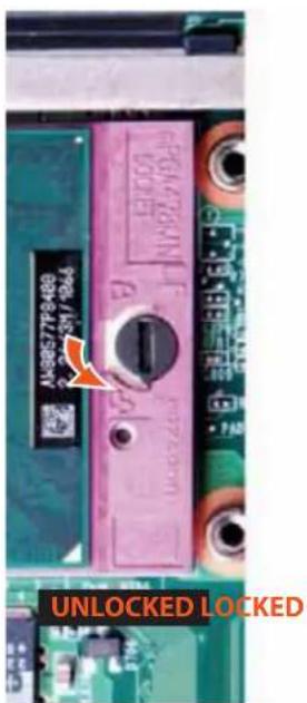

Please ensure that the notch on the screw faces the "unlocked" symbol on the CPU socket before inserting the CPU as shown on the left. In this position, it is possible to insert the processor.
IMPORTANT: Please verify the correct orientation of the CPU with the golden triangle on the CPU package positioned as shown below. After inserting the CPU, turn the screw so that the notch faces the “locked” symbol as shown on the right picture above.

Note that the screw is in the " unlocked" position
The heat sink is factory-precoated with a “phase change” thermal interface material (TIM) pad. In the case of a new system and CPU, this TIM pad works very well, however, it cannot be re-used without leaving gaps on the CPU heat sink interface. If the cooler needs to be reseated or a new CPU is installed as replacement of the previous one, please clean both CPU and the cooler from any residual TIM pad and apply new thermal compound like OCZ FreeZe to the CPU.

Note that the screw notch is in the "locked" position.
Carefully re-assemble the system in reverse order of the disassembly.
Congratulations! You have successfully configured your very own mobile gaming solution. Attach your battery and plug in your fully configured notebook to begin the software installation process. Please remember to fully charge your notebook battery (approx. 5 hours) before attempting to game on the go.


OCZ Technology Inc.
860 E. Arques Ave.,
Sunnyvale, CA 94085 USA
(408) 733-8400 Phone
(408) 733-5200 Fax
(408) 733-8400 Sales

Brand : OCZ Technology
Model : DIY 15" Gaming Notebook
Category : Laptop