
VC-203PR - Network card Planet - Free user manual and instructions
Find the device manual for free VC-203PR Planet in PDF.


| Product Type | Network Interface Card (NIC) |
| Model | VC-203PR |
| Brand | Planet |
| Interface Type | PCI Express (PCIe) |
| Port Configuration | Single RJ-45 |
| Data Rate | 10/100/1000 Mbps (Gigabit Ethernet) |
| Connector | RJ-45 |
| Cable Type | Cat5e / Cat6 UTP |
| Dimensions (W x D x H) | 120 x 75 x 20 mm (approx.) |
| Weight | 50 g (approx.) |
| Power Consumption | 2.5 W (typical) |
| Power Source | PCIe bus power |
| Operating Temperature | 0°C to 40°C |
| Storage Temperature | -10°C to 70°C |
| Operating Humidity | 10% to 90% (non-condensing) |
| LED Indicators | Link/Activity, Speed |
| Supported Operating Systems | Windows, Linux, macOS |
| Compliance | IEEE 802.3, 802.3u, 802.3ab |
| Warranty | Limited lifetime warranty |
| Package Contents | Network card, low-profile bracket, manual |
Frequently Asked Questions - VC-203PR Planet
User questions about VC-203PR Planet
0 question about this device. Answer the ones you know or ask your own.
Ask a new question about this device
Download the instructions for your Network card in PDF format for free! Find your manual VC-203PR - Planet and take your electronic device back in hand. On this page are published all the documents necessary for the use of your device. VC-203PR by Planet.
USER MANUAL VC-203PR Planet
Power over Coaxial Extender
VC-203PT and VC-203PR
User's Manual
Trademarks
Copyright © PLANET Technology Corp. 2013.
Contents are subject to revision without prior notice.
PLANET is a registered trademark of PLANET Technology Corp. All other trademarks belong to their respective owners.
Disclaimer
PLANET Technology does not warrant that the hardware will work properly in all environments and applications, and makes no warranty and representation, either implied or expressed, with respect to the quality, performance, merchantability, or fitness for a particular purpose.
PLANET has made every effort to ensure that this User's Manual is accurate; PLANET disclaims liability for any inaccuracies or omissions that may have occurred.
Information in this User's Manual is subject to change without notice and does not represent a commitment on the part of PLANET. PLANET assumes no responsibility for any inaccuracies that may be contained in this User's Manual. PLANET makes no commitment to update or keep current the information in this User's Manual, and reserves the right to make improvements to this User's Manual and/or to the products described in this User's Manual, at any time without notice.
If you find information in this manual that is incorrect, misleading, or incomplete, we would appreciate your comments and suggestions.
FCC Warning
This equipment has been tested and found to comply with the limits for a Class A digital device, pursuant to Part 15 of the FCC Rules. These limits are designed to provide reasonable protection against harmful interference when the equipment is operated in a commercial environment. This equipment generates, uses, and can radiate radio frequency energy and, if not installed and used in accordance with the Instruction manual, may cause harmful interference to radio
communications. Operation of this equipment in a residential area is likely to cause harmful interference in which case the user will be required to correct the interference at his own expense.
CE Mark Warning
This is a Class A product. In a domestic environment, this product may cause radio interference, in which case the user may be required to take adequate measures.
WEEE Warning

To avoid the potential effects on the environment and human health as a result of the presence of hazardous substances in electrical and electronic equipment, end users of electrical and electronic equipment should understand the meaning of the crossed-out wheeled bin symbol. Do not dispose of WEEE as unsorted municipal waste and have to collect such WEEE separately.
Revision
PLANET Industrial Power over Coaxial Extender User's Manual
For Model: VC-203PT / VC-203PR
Revision: 1.0 (May, 2013)
Part No: EM-VC-203PT_203PR_v1.0 (2350-AC0300-000)
Table of Contents
1. INTRODUCTION .... 5
1.1 Package Contents 5
1.2 Product Features....6
1.3 Product Specifications .... 7
1.4 Physical Dimensions....10
2. INSTALLATION ....12
2.1 Product Description....12
2.1.1 Power over Coaxial Extender Front Panel ....13
2.1.2 LED Indicators ....13
2.1.3 Power over Coaxial Extender Rear Panel ....15
2.2 Applications of VC-203PT and VC-203PR....16
3. TROUBLESHOOTING ....20
APPENDIX A: NETWORKING CONNECTION ......22
A.1 Switch's RJ-45 Pin Assignments ......22
A.2 RJ-45 Cable Pin Assignments ......22
1. INTRODUCTION
Thank you for purchasing PLANET Industrial Power over Coaxial Extender, VC-203PT and VC-203PR. The descriptions of the two models are as follows:
| VC-203PT | PoE over Coaxial Extender - Transmitter(1-Port 10/100TX 802.3at PoE PD + 1-Port BNC PoE) |
| VC-203PR | PoE over Coaxial Extender - Receiver(1-Port 10/100TX 802.3at PoE PSE + 12/24V DC Splitter) |
"Industrial Power over Coaxial Extender" mentioned in this Manual represents the above two models.
1.1 Package Contents
Open the box of the Industrial Power over Coaxial Extender and carefully unpack it. The box should contain the following items:
| For VC-203PT For VC-203PR | |
| Industrial Power over Coaxial Extender – Transmitter x 1User’s Manual x 1Power Adapter and Power Cord | Industrial Power over Coaxial Extender –Receiver x 1User’s Manual x 1 |
If any of these are missing or damaged, please contact your dealer immediately; if possible, retain the carton including the original packing material, and use them again to repack the product in case there is a need to return it to us for repair.
1.2 Product Features
Physical Port
| Model Name | Ports | |
| Copper BNC | ||
| VC-203PT 1 x 10/100Base-TX (PoE IN) Power/Data Transmitter | ||
| VC-203PR 1 x 10/100Base-TX (PoE OUT) Power/Data Receiver | ||
Power over Ethernet
Eliminates Power cabling with PoE over Coaxial ●
Ethernet over coaxial up to 1km with 5C2V/RG6 75Ω cable ●
Complies with IEEE 802.3af / IEEE 802.3at Power over Ethernet on RJ-45 ports

● Supports PoE Power up to 30.8 watts (Vary on Power Source and Coaxial Distance)
● Auto detect powered device (PD) (VC-203PR)
Layer 2 Features
● Supports Auto-negotiation and 10/100Mbps half / full duplex mode
● Prevents packet loss with back pressure (Half-Duplex) and IEEE 802.3x PAUSE frame flow control (Full-Duplex)
VDSL2 Features
● One box design, Master / Slave selectable via DIP Switch
- Defines Asymmetric (Band Plan 998) and Symmetric band plans for the transmission of Upstream and Downstream signals
Industrial Case / Installation
● Supports extensive LED indicators for network diagnostics
●P30 metal case protection
- Compact size, DIN Rail and Wall Mount Design
● Power Input: External DC or PoE power input
● Supports EFT protection 2000 VDC for power line
●Supports 2000 VDC Ethernet ESD protection
-40 to 75 degrees C operating temperature
1.3 Product Specifications
| Model VC-203 | PT VC-203PR | ||
| Hardware Specifications | |||
| Interface | Copper | 10/100Base-TX RJ-45Auto-negotiation/Auto-MDI/MDI-X802.3at/af PoE Input | 10/100Base-TX RJ-45Auto-negotiation/Auto-MDI/MDI-X802.3at/af PoE Output |
| Coaxial | BNC, femalePower over Coaxial Output | BNC, femalePower over Coaxial Input | |
| DC Socket(Optional) | 52~56V DC Input | ||
| DIP-Switch | 2-Position DIP Switch■ Selectable CO or CPE mode (Default: CPE)■ Selectable Band plan: Asymmetric or Symmetric (Default: Asymmetric) | 2-Position DIP Switch(Front)■ Selectable CO or CPE mode (Default: CO)■ Selectable Band plan: Asymmetric or Symmetric (Default: Asymmetric) | |
| --- | 2-Position DIP Switch(Rear)■ PoE out or DC out(Default: PoE out)■ 12V DC / 24V DC output voltage(Default: 12V DC) | ||
| LED Indicators | LED is Green Color■ PWR■ PoE IN■ LNK■ CO■ CPE■ LNK/ACT■ 100 | LED is Green Color■ PWR■ PoE IN■ PoE Out■ LNK■ CO■ CPE■ LNK/ACT■ 100 | |
| ESD Protection 2KV DC | |||
| EFT Protection 2KV DC | |||
| Enclosure IP30 metal case | |||
| Installation Wall mount | or DIN rail with optional kit | ||
| Dimensions(W x D x H) | 94 x 70.3x 39.2 mm | ||
| Weight 288g 302g | |||
| Power Requirements | ■ RJ-45 PoE Input:802.3at/af 44~57V DC■ DC Input: 52~56V DC | ■ BNC Power over CoaxialInput: 44~57V DC■ DC Input: 52~56V DC | |
| Performance*(Down / Up Stream) | Asymmetric Mode (Data Only) | ||
| 200m -> 100/65Mbps 800m -> 100/53Mbps400m -> 100/64Mbps 1000m -> 94/44Mbps600m -> 100/59Mbps 1200m -> 84/36Mbps | |||
| Symmetric Mode (Data Only) | |||
| 200m -> 100/100Mbps 800m -> 79/80Mbps400m -> 97/100Mbps 1000m -> 69/66Mbps600m -> 86/91Mbps 1200m -> 60/52Mbps | |||
| Power over Ethernet/Coaxial | |||
| PoE Standard | IEEE 802.3at Type 2IEEE 802.3af | ||
| PSE Interface | BNC44~57V DC(Depend on what is theDC/PoE Power Input) | RJ-4548~56V DC, 600mA max.End-Span, Pin 1/2(+),3/6(-) | |
| PD Interface | RJ-45, both Mid-Span andEnd-SpanInput Range: 44~57V DC | BNCInput Range: 44~57V DC | |
| DC Power Output - | 12V DC, 2A max.24V DC, 1A max. | ||
| Max.PoEBudget | Power Inputby PoE | BNC : 25 watts RJ-45 : 20 watts | |
| Power Inputby DC | BNC : 30 watts RJ-45 : 30 watts | ||
| Standards Conformance | |||
| StandardsCompliance | IEEE 802.3 10Base-T EthernetIEEE 802.3u 100Base-TX Fast EthernetIEEE 802.3af Power over Ethernet (802.3at Type 1)IEEE 802.3at Power over Ethernet Plus (802.3at Type 2) | ||
| Regulation Compliance | FCC Part 15 Class A, CE | ||
| Environment | |||
| Temperature | Operating: -40~75 degrees CStorage: -40~75 degrees C | ||
| Humidity | Operating: 5~95% (Non-condensing)Storage: 5~95% (Non-condensing) | ||
| Cable | |||
| Coaxial | RG-6/U cable (Recommended)max. 500 m with PoE+ (1,640 ft.)max. 700 m with PoE (2,297 ft.)max. 1200 m without PoE (3,937 ft.) | ||
* The actual data rate will vary on the quality of the copper wire and environment factors.

Please take care of the conditions of the resistance value of cables as follows.
| Coaxial Cable Type | |
| RG-59/U Less than 30Ω/1 | 000 ft. |
| RG-6/U Less than 12Ω/10 | 00 ft |
Because there are various resistance values in the category of RG-59/U or RG-6/U cable.
1.4 Physical Dimensions
■ VC-203PT dimensions (W x D x H): 94 x 70.3 x 39.2 mm

■ VC-203PR dimensions (W x D x H): 94 x 70.3 x 39.2 mm

2. INSTALLATION
This section describes the functionalities of the Industrial Power over Coaxial Extender's components and guides you to how to install it on the desktop. Basic knowledge of networking is expected. Please read this chapter completely before continuing.
2.1 Product Description
Power over Coaxial
Based on IEEE 802.3at high power over Ethernet and up to 25 watts of power output, PLANET PoE over coaxial extender solution eliminates the need for additional remote site power while allowing a single PoE source, such as a PoE network switch, to provide power to both transceivers and the camera at long range. This feature eliminates the need for local and remote site power supplies.
IEEE 802.3at/af PoE Injector and Splitter in one box design
The VC-203PR is a Single-Port, 802.3at High Power over Ethernet Injector providing maximum up to 30 watts of power output over Ethernet cable which allows data and power to transmit simultaneously through the cable to PoE PD (Powered Device). In addition, the VC-203PR also features PoE splitter function with selectable 12V/24V DC power output which makes non-PoE equipment power up as well.
Stable Operating Performance under Difficult Environments
The VC-203PT and VC-203PR extender is the perfect solution for extended distance data and power transmission for warehouses, parking lots, campuses, casinos, and many more. They can operate stably under temperature range from -40 to 75 degrees C which enables the users to conveniently apply the device in almost any location of the network.
2.1.1 Power over Coaxial Extender Front Panel
Figure 2-1 and Figure 2-2 show the front panels of the VC-203PT and VC-203PR Industrial Power over Coaxial Extenders.


Figure 2-1: VC-203PT front panel Figure 2-2: VC-203PR front panel
■ Front Panel DIP Switch Setting
The front panels of the VC-203PT and VC-203PR provide one 2-DIP switch which is for configuring coaxial link CO/CPE mode and Band plan function.
Refer to the table below to know about the 2-DIP switch settings and descriptions:

| DIP-1 | DIP-2 | |
| Mode | Band Plan | |
| OFF | CO | Symmetric |
| ON | CPE | Asymmetric |
2.1.2 LED Indicators
■ System
| LED | Color | Function |
| PWR | Green | Light: indicates the power is on. |
■ Coaxial / VDSL2 Interfaces
| LED Color Function | ||
| LNK Green | Light: indicates that the coaxial link is established. | |
| Fast Blink: indicates that the coaxial link is at training status (about 10 seconds). | ||
| Slow Blink: indicates that the coaxial link is at idle status. | ||
| CO Green | Light: indicates the coaxial Bridge is running at CO mode. | |
| CPE Green | Light: indicates the coaxial Bridge is running at CPE mode. | |
■ RJ-45 10/100Base-TX Interfaces
| LED Color Function | ||
| 100 Green | Light: indicates the extender is successfully connecting to the network at 100Mbps. | |
| OFF: indicates the extender is successfully connecting to the network at 10Mbps. | ||
| LNK/ACT Green | Blink: indicates the extender is actively sending or receiving data over that port. | |
■ RJ-45 PoE Indicators
| LED Color Model Function | |||
| PoE IN Green | VC-203PT | Light: indicates the RJ-45 port is receiving the PoE Power. | |
| VC-203PR | Light: indicates the BNC connector is receiving the PoE Power. | ||
| PoE Out | Green VC-203PR | Light: indicates the RJ-45 Port is providing PoE power | |
2.1.3 Power over Coaxial Extender Rear Panel
Figure 2-3 and Figure 2-4 show the rear panels of the VC-203PT and VC-203PR Industrial Power over Coaxial Extenders.

Figure 2-3: VC-203PT rear panel

Figure 2-3: VC-203PR rear panel
■ VC-203PR Rear Panel: DIP Switch Setting

| DIP-1 DIP-2 | |
| Power Output Voltage | |
| DC Out 24V | |
| PoE Out (default) 12V (default) | |
■ VC-203PR Rear Panel: 2-Pin Terminal Block
If there is no power socket in the network environment for Non-PoE networked device, the VC-203PR can be of great help by conveniently and easily providing this Ethernet device with DC power. Via the DIP switch configuration, the VC-203PR separates the power out and provides two kinds of DC power output and its voltage and current are shown below:
12V DC, 2A max.
24V DC, 1A max.

Caution
- VC-203PR has two power output options; only one mode is available at one time. It cannot use DC power output if power output of DIP switch is in PoE output position.
- Disconnect "PoE IN" coaxial cable before changing 12/24V DIP Switch.
- Incorrect voltage from "DC Out" might cause damage to connected device.
2.2 Applications of VC-203PT and VC-203PR
Type 1 - VC-203PT with 52\~56V power adapter and VC-203PR with PoE power output
110-240V AC
![graph LR A["AC-to-DC Adapter 60W/52~56V DC IN"] --> B["PLANET"] C["Ethernet Switch"] --> D["VC-203PT Transmitter / VDSL2 CPE"] D --> E["Power over Coaxial"] E --> F["VC-203PR Receiver / VDSL2 CO"] F --> G["802.3af/802.3at"] G --> H["RJ-45"] H --> I["PoE IP Camera"] J["RJ-45"] --> D](/content/2026/05/1072618/images/65c24c2f3a19ea9b779923af14e86f36bae31e288951d88fa2d27de3e1cb24ec.jpg)
| CPE CO | ||
| VC-203PT VC-203PR | ||
| Power Input | Power adapter with 52~56V DC in | BNC with DC power over coaxial input |
| Power Output | BNC with DC power over coaxial output | RJ-45 with 802.3at/af PoE output |

Caution
- PoE Output Capacity is based on different DC Power Input / PoE Input.
- VC-203PT has two power input options; only one mode is available at one time. It cannot use PoE power input if power input of DC 52V or 56V is selected.
Type 2 - VC-203PT with 52\~56V power adapter and VC-203PR with DC power output
110-240V AC
![graph LR A["AC-to-DC Adapter 60W/52~56V DC IN"] --> B["Planet"] C["Ethernet Switch"] --> D["VT"] D --> E["VC-203PT Transmitter / VDSL2 CPE"] E --> F["Power over Coaxial"] F --> G["VC-203PR Receiver / VDSL2 CO"] G --> H["Data RJ-45"] H --> I["12V/24V DC"] I --> J["Non-PoE IP Camera"] D --> K["RJ-45"]](/content/2026/05/1072618/images/57b29c18cd68c1e12aa7dc11f47a3844d2762da639bc9135e504e5759df2bb4d.jpg)
| CPE CO | ||
| VC-203PT VC-203PR | ||
| Power Input | Power adapter with 52~56V DC in | BNC with DC power over coaxial input |
| Power Output | BNC with DC power over coaxial output | DC Terminal block with 12V or 24V DC output |

- Please ensure the VC-203PR output voltage is correct for remote device.
- Please plug off the PoE Coaxial cable from VC-203PR before switching off the Power Voltage DIP during operation. Wait for 3 seconds until the "PoE IN" LED is completely OFF. Otherwise, it might damage your devices.
Type 3 - VC-203PT with PoE power input and VC-203PR with PoE power output
![graph LR A["802.3af / 802.3at PoE Switch"] -->|PoE| B["PLANET"] B --> C["Transmitter / VDSL2 CPE"] C --> D["Power over Coaxial"] D --> E["VC-203PT"] E --> F["VC-203PR Receiver / VDSL2 CO"] F --> G["802.3af / 802.3at"] G --> H["RJ-45"] H --> I["POE IP Camera"]](/content/2026/05/1072618/images/fa07ad2429bb652819f5d830452f1c577e4b85cb89114494c5d1c8a1f384dcb4.jpg)
| CPE CO | ||
| VC-203PT VC-203PR | ||
| Power Input | RJ-45 with 802.3at/af PoE input | BNC with DC power over coaxial input |
| Power Output | BNC with DC power over coaxial output | RJ-45 with 802.3at/af PoE output |

The VC-203PT accepts IEEE 802.3at equipment for optimal power injection. Any other Non-standard PoE Power devices may cause the VC-203PT to malfunction.
Type 4 - VC-203PT with PoE power input and VC-203PR with DC power output
![graph LR A["802.3af / 802.3at PoE Switch"] -->|PoE| B["PLANET"] C["RJ-45"] -->|RJ-45| B B --> D["VC-203PT Transmitter / VDSL2 CPE"] D -->|Power over Coaxial| E["VC-203PR Receiver / VDSL2 CO"] E --> F["12V/24V DC"] F --> G["Non-PoE IP Camera"]](/content/2026/05/1072618/images/36dea7e90aff7563bf2de1dc9409f7fc545f0e14175cadc4a724e4e6b19f3749.jpg)
| CPE CO | ||
| VC-203PT VC-203PR | ||
| Power Input | RJ-45 with 802.3at/af PoE input | BNC with DC power over coaxial input |
| Power Output | BNC with DC power over coaxial output | DC Terminal block with 12V or 24V DC output |
Type 5 - PLANET VC-202A (does not support Power over coaxial) with coaxial link to VC-203PR and VC-203PR get external DC power input directly and RJ-45 with PoE output
![graph LR A["Ethernet Switch"] -->|RJ-45| B["PLANET"] B -->|Coaxial Cable| C["VC-203PR Receiver / VDSL2 CO"] C --> D["AC-to-DC Adapter 60W/52~56V DC IN"] D --> E["802.3af / 802.3at"] E --> F["RJ-45"] G["PoE IP Camera"] --> H["Return to PC"] I["VC-202A VDSL2 CPE"] --> B](/content/2026/05/1072618/images/e36ad3baa3e42862f7baf6c8330568523cfdeb240ddd3694019571da7bcab895.jpg)
![graph LR A["Ethernet Switch"] -->|RJ-45| B["PLANET"] B --> C["VC-202A VDSL2 CPE"] C --> D["Coaxial Cable"] D --> E["VC-203PR Receiver / VDSL2 CO"] E --> F["AC-to-DC Adapter 60W/52~56V DC IN"] F --> G["Non-PoE IP Camera"] G --> H["RJ-45"] H --> I["12V/24V DC"]](/content/2026/05/1072618/images/168e45c3abf0c821e603f3048a5286c4f3c3222004d20491624e8c2f388bde8f.jpg)
| CPE CO | ||
| VC-202A / IVC-2002 VC-203PR | ||
| Power Input | Power adapter with 5V DC in | Power adapter with 52~56V DC in |
| Power Output | does not support power output | RJ-45 with 802.3at/af PoE outputDC Terminal block with 12V or 24V DC output |

Caution
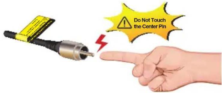
As the VC-203PT is power over coaxial, please confirm that other Non-PoE equipment is not connected with the coaxial cable. When you connect the coaxial cable with coax-LAN converter, CCTV camera, etc, it might cause other equipment to damage.
3. TROUBLESHOOTING
This chapter contains information to help you solve issues. If the Industrial Power over Coaxial Extender is not functioning properly, make sure the Industrial Power over Coaxial Extender was set up according to instructions in this manual.
VDSL LNK LED does not light after wire is connected to the VDSL port.
CHECKPOINT:
- Verify the length of the wire connected between VC-203PT and VC-203PR. It should not be more than 2.4km.
- Please note you must use one for CO mode and the other with CPE mode, and connect to each other to make it work.
TP LED does not light after cable is connected to the port.
CHECKPOINT:
- Verify you are using the Cat.5, 5e or 6 cables with RJ-45 connector to connect to the port.
- If your device (like LAN card) supports Auto-Negotiation, please try to manually modify at a fixed speed of your device.
- Check whether the power of the converter and the connected device is ON or OFF.
4 Check the port's cable is firmly seated in its connectors in the switch and in the associated device. - Check the connecting cable is good.
- Check the power adapters are functional, including the connecting device.
Performance is bad
CHECKPOINT:
The actual data rate will vary on the quality of the coaxial cable and environment factors.
Why can't power be on when my PoE PD device is connected to VC-203PR?
CHECKPOINT:
- Please check the cable type of the connection from VC-203PR to the other end. The cable should be an 8-wire UTP, Category 5 or above, and EIA568 cable within 100 meters. A cable with only 4-wire, short loop or over 100 meters will affect the power supply.
- Please check and assure the device is fully complied with IEEE 802.3af / IEEE 802.3at standard.
APPENDIX A: NETWORKING CONNECTION
A.1 Switch's RJ-45 Pin Assignments
10/100Mbps, 10/100Base-TX
| RJ-45 Connector pin assignment | ||
| Contact | MDIMedia Dependant Interface | MDI-XMedia Dependant Interface-Cross |
| 1 Tx + (transmit) Rx + (receive) | ||
| 2 Tx - (transmit) Rx - (receive) | ||
| 3 Rx + (receive) Tx + (transmit) | ||
| 4, 5 Not used | ||
| 6 Rx - (receive) Tx - (transmit) | ||
| 7, 8 Not used | ||
A.2 RJ-45 Cable Pin Assignments

The standard RJ-45 receptacle/connector
There are 8 wires on a standard UTP/STP cable and each wire is color-coded. The following shows the pin allocation and color of straight cable and crossover cable connection:
Figure A-1: Straight-Through and Crossover Cable
Please make sure your connected cables are with the same pin assignment and color as the above picture before deploying the cables into your network.
EC Declaration of Conformity
For the following equipment:
*Type of Product: PoE over Coaxial Extender - Transmitter PoE over Coaxial Extender - Receiver with 12/24V DC Splitter
*Model Number: VC-203PT & VC-203PR
* Produced by:
Manufacturer's Name : Planet Technology Corp.
Manufacturer's Address: 10F., No.96, Minquan Rd., Xindian Dist.
New Taipei City 231, Taiwan (R.O.C.).
When hereby confirmed that the products mentioned comply with the requirements set out in the Council Directive on the Approximation of the Laws of the Member States relating to Electromagnetic Compatibility (2004/108/EC).
For the evaluation regarding the EMC, the following standards were applied:
EN55022 (2006 + A1 :2007)
EN 61000-3-2 (2006 + A1:2009 + A2:2009)
EN 61000-3-3 (2008)
EN55024 (2010)
Responsible for marking this declaration if the:
Manufacturer ☐ Authorized representative established within the EU
Authorized representative established within the EU (if applicable):
Company Name: Planet Technology Corp.
Company Address: 10F., No.96, Minquan Rd., Xindian Dist., New Taipei City 231, Taiwan (R.O.C.)
Person responsible for making this declaration
Name, Surname Kent Kang
Position / Title : Product Manager
Taiwan Place
1st July, 2013 Date
Lout Fang Legal Signature
- POWER OVER COAXIAL EXTENDER
- TRADEMARKS
- DISCLAIMER
- FCC WARNING
- CE MARK WARNING
- WEEE WARNING
- REVISION
- TABLE OF CONTENTS
- INTRODUCTION .... 5
- INSTALLATION ....12
- TROUBLESHOOTING ....20
- APPENDIX A: NETWORKING CONNECTION ......22
- INTRODUCTION
- 1.1 PACKAGE CONTENTS
- 1.2 PRODUCT FEATURES
- POWER OVER ETHERNET
- LAYER 2 FEATURES
- VDSL2 FEATURES
- INDUSTRIAL CASE / INSTALLATION
- 1.3 PRODUCT SPECIFICATIONS
- 1.4 PHYSICAL DIMENSIONS
- INSTALLATION
- 2.1 PRODUCT DESCRIPTION
- POWER OVER COAXIAL
- IEEE 802.3AT/AF POE INJECTOR AND SPLITTER IN ONE BOX DESIGN
- STABLE OPERATING PERFORMANCE UNDER DIFFICULT ENVIRONMENTS
- 2.1.1 POWER OVER COAXIAL EXTENDER FRONT PANEL
- FRONT PANEL DIP SWITCH SETTING
- 2.1.2 LED INDICATORS
- 2.1.3 POWER OVER COAXIAL EXTENDER REAR PANEL
- VC-203PR REAR PANEL: DIP SWITCH SETTING
- VC-203PR REAR PANEL: 2-PIN TERMINAL BLOCK
- 2.2 APPLICATIONS OF VC-203PT AND VC-203PR
- TROUBLESHOOTING
- VDSL LNK LED DOES NOT LIGHT AFTER WIRE IS CONNECTED TO THE VDSL PORT
- CHECKPOINT
- TP LED DOES NOT LIGHT AFTER CABLE IS CONNECTED TO THE PORT
- PERFORMANCE IS BAD
- WHY CAN'T POWER BE ON WHEN MY POE PD DEVICE IS CONNECTED TO VC-203PR
- APPENDIX A: NETWORKING CONNECTION
- A.1 SWITCH'S RJ-45 PIN ASSIGNMENTS
- A.2 RJ-45 CABLE PIN ASSIGNMENTS
- EC DECLARATION OF CONFORMITY
Brand : Planet
Model : VC-203PR
Category : Network card