Motorhome Premium Class (2010) - Motorhome Dethleffs - Free user manual and instructions
Find the device manual for free Motorhome Premium Class (2010) Dethleffs in PDF.

| Product Type | Motorhome |
| Brand | Dethleffs |
| Model | Premium Class (2010) |
| Year | 2010 |
| Overall Length | Approx. 7.5 m (24.6 ft) |
| Overall Width | Approx. 2.3 m (7.5 ft) |
| Overall Height | Approx. 3.0 m (9.8 ft) |
| Gross Vehicle Weight Rating (GVWR) | 4,500 kg (9,920 lbs) |
| Payload Capacity | Approx. 800 kg (1,764 lbs) |
| Fuel Type | Diesel |
| Engine | 3.0L Turbo Diesel (approx. 160 hp) |
| Transmission | 6-speed Manual or 6-speed Automatic |
| Sleeping Capacity | 4-6 persons |
| Fresh Water Tank | 120 L (31.7 gal) |
| Waste Water Tank | 90 L (23.8 gal) |
| Propane Tank Capacity | 2x 11 kg (24.3 lbs) |
| Electrical System | 12V DC / 230V AC with 100 Ah house battery |
| Refrigerator | 132 L (4.7 cu ft) compressor fridge |
| Furnace | Gas forced-air furnace 6 kW |
| Air Conditioning | Roof-mounted 2.7 kW A/C |
| Awning | Manual roll-out awning (approx. 4.5 m) |
| Safety Equipment | Smoke detector, CO detector, LP gas detector, fire extinguisher |
| Spare Parts Availability | Available from Dethleffs dealers and online |
Frequently Asked Questions - Motorhome Premium Class (2010) Dethleffs
User questions about Motorhome Premium Class (2010) Dethleffs
0 question about this device. Answer the ones you know or ask your own.
Ask a new question about this device
Download the instructions for your Motorhome in PDF format for free! Find your manual Motorhome Premium Class (2010) - Dethleffs and take your electronic device back in hand. On this page are published all the documents necessary for the use of your device. Motorhome Premium Class (2010) by Dethleffs.
USER MANUAL Motorhome Premium Class (2010) Dethleffs
We congratulate you on your new motorhome and would like to thank you for choosing a quality product from Dethleffs.
Whether you want to enjoy your holidays on good or bad roads, whether you want to have your "holiday home" out in the country, at the seaside or in the mountains: Your Dethleffs motorhome will always make sure that you can enjoy your holidays because the Dethleffs team has been building caravans for more than seventy years and knows what is important. This experience shows itself in the well thought-out, cosy and yet highly functional equipment as well as in the outstanding driving characteristics.
Each Dethleffs vehicle is manufactured with great care and the quality is closely checked. This ensures that our products have a long service life. In view of these strict requirements, we guarantee top quality of our products and grant you a six year leakage guarantee of the body in accordance with our guarantee conditions (see section 1.2).
This instruction manual deals primarily with the body of your motorhome. It will give you all important information and tips so that you can enjoy all technical advantages of your Dethleffs motorhome to the full. We have also included a chapter on maintenance – and thus on the conservation of value.
In addition, you will find the documents on the base vehicle and the various built-in appliances.
For maintenance work or whenever you need some help, please always get in touch with your authorised specialist workshop. They know your motorhome best of all, and will meet all your requests fast and reliably.
We wish you a lot of fun with your motorhome, a relaxing holiday and safe driving at all times.
Your Dethleffs team
1.1 Guarantee certificate....7
1.2 Guarantee conditions ..... 7
1.3 Inspection records....9
1.4 Inspection plan for annual inspection 12
1.5 Inspection plan for water ingress test .... 12
2 l n t r o
2.1 General 16
2.2 Environmental tips.... 16
3 S a f e t
3.1 Fire prevention 19
3.1.1 Avoidance of fire risks.... 19
3.1.2 Fire-fighting 19
3.1.3 In case of fire. 19
3.2 General 20
3.3 Road safety.... 20
3.4 Towing.... 22
3.5 Gas system.... 22
3.5.1 General instructions 22
3.5.2 Gas bottles 23
3.6 Electrical system 24
3.7 Water system 24
4 Before the journey ..... 25
4.1 Keys 25
4.2 Registration.... 25
4.3 Payload 26
4.3.1 Terms 26
4.3.2 Calculating the payload.... 28
4.3.3 Loading the vehicle correctly.....29
4.3.4 Roof load.... 31
4.3.5 Rear garage 32
4.3.6 Double floor.... 33
4.3.7 Sliding drawer 33
4.3.8 Bike rack 33
4.4 Towing.... 34
4.5 Entrance step 34
4.6 PVC-floor covering 36
4.7 Television 36
4.8 Sink cover 37
4.9 Roman shades for driver's window and front passenger's window ..... 38
4.10 Central locking system for kitchen unit 38
4.11 Snow chains 39
4.12 Road safety.... 39
5 During the journey ..... 41
5.1 Driving the motorhome 41
5.2 Reversing camera. 42
5.3 Driving speed 42
5.4 Brakes.... 42
5.5 Seat belts....43
5.5.1 Fastening the seat belt correctly ..... 43
5.6 Driver's seat and front passenger's seat 43
5.7 Headrests 46
5.8 Seating arrangement ..... 46
5.9 Electrically adjustable external mirrors 47
5.10 Sun visors 47
d5.11 Pneumatic spong....t....i....48o n
5.11.1 Pneumatic spring (Goldschmidt) ..... 48
5.11.2 Pneumatic spring (VB-air suspension) 49
5.12 Bonnet 19.51
5.13 Filling with washer fluid 52
5.14 Refilling cooling water ..... 52
5.15 Filling up with diesel....53
6 Pitching the motorhome.....55
6.1 Handbrake 55
6.2 Entrance step....55
6.3 Wheel chocks 55
6.4 Supports 55
6.4.1 General instructions....55
6.4.2 Steady legs 56
6.4.3 Electrical steady legs 56
6.4.4 Electrical-hydraulic steady legs ..... 58
6.5 240 V connection....60
6.6 Awning 60
7 L i v i n g
7.1 Doors 63
7.1.1 Conversion door, outside. 64
7.1.2 Conversion door, outside (Hartal) .... 64
7.1.3 Conversion door, inside ..... 65
7.1.4 Conversion door, inside (Hartal) ..... 65
7.1.5 Window conversion door ..... 65
7.1.6 Window of conversion door (Hartal) 66
7.1.7 Folding insect screen on the conversion door 66
7.2 External flaps....67
7.2.1 Flap lock with recessed handle ..... 67
7.2.2 Flap lock with separate locking cylinder 68
7.2.3 Sliding drawer 69
7.3 Driver's cabin partition ..... 69
7.4 Ventilation 70
7.5 Windows 70
7.5.1 Hinged window with automatic hinges (with safety knob)....71
7.5.2 Sliding window with lock ..... 72
7.5.3 Sliding window without lock ..... 73
7.5.4 Gathered blinds 73
7.5.5 Blind and insect screen ..... 73
7.5.6 Roman shade and insect screen ..... 74
7.5.7 Blind for the windscreen....75
7.5.8 Roman shades for driver's window and front passenger's window ..... 76
7.6 Skylights....76
7.6.1 Skylight with snap latch ..... 77
7.6.2 Hinged skylight....78
7.6.3 Heki skylight (mini and midi) ..... 79
7.6.4 Wind-up skylight 80
7.7 Rotating seats 81
7.8 Tables 81
7.8.1 Suspension table with folding table-top extension....81
7.8.2 Fixed table (movable table-top) ..... 82
7.9 Central locking system for kitchen unit....82
7.10 Television....83
7.11 Lamps 84
7.12 Light switch 85
7.13 Light control 86
7.14 Remote control for awning light, canopy light and entrance step ..... 86
7.15 Extending the seating group ..... 87
7.15.1 Extending the central seating group 87
7.15.2 Extending the central seating group with divan ..... 88
7.16 Beds....88
7.16.1 Overcab bed 88
7.16.2 Pull-down bed, electronically lowerable ..... 89
7.16.3 Fixed bed (gas-pressure springs) .... 91
7.17 Converting seating groups for sleeping 92
7.17.1 Central seating group....92
7.17.2 Central seating group with extension 93
7.17.3 Central seating group with divan ..... 94
8 Gas system....95
8.1 General 95
8.2 Gas bottles....96
8.3 Gas consumption....97
8.4 Changing gas bottles ..... 97
8.5 Gas isolator taps ..... 98
8.6 Hose break guard (crash protection unit) ..... 98
8.7 External gas connection ..... 99
8.8 Duomatic switching facility.....100
8.9 DuoControl switching facility ..... 102
9 Electrical system....105
9.1 General safety instructions ..... 105
9.2 Terms.....105
9.3 12 V power supply ..... 106
9.3.1 Living area battery ..... 106
9.4 Charging the living area battery and starter battery .....107
9.4.1 Charging using a 240 V power supply ....108
9.4.2 Charging using the vehicle engine . . .108
9.4.3 Charging with an external charger . . .108
9.5 AC converter.....109
9.6 Auxiliary charging unit .....110
9.7 Transformer/rectifier (EBL 220) .....110
9.7.1 Battery separation .....112
9.7.2 Battery selector switch .....112
9.7.3 Battery monitor .....112
9.7.4 Charging the battery.....113
9.8 Panel MP 20-T .....113
9.8.1 240 V indicator lamp.....114
9.8.2 12 V main switch .....114
9.8.3 Batteries gauge .....115
9.8.4 Tank gauge....117
9.8.5 Alarms 117
9.8.6 Temperature display.....118
9.8.7 Clock gauge .....118
9.8.8 Switch for tank heater.....118
9.9 240 V power supply .....118
9.9.1 240 V connection .....119
9.9.2 Power cable for external 240 V connection .....119
9.10 Fuses 120
9.10.1 12 V fuses....120
9.10.2 240 V fuse .....122
10 Appliances....123
10.1 General....123
10.2 Alde hot-water heater .....124
10.2.1 Alde heat exchanger.....126
10.2.2 Alde auxiliary circulating pump .....127
10.2.3 Setting the rotational speed of the circulating pump .....127
10.3 Independent vehicle heater .....128
10.4 Alde boiler....129
10.4.1 Switching the boiler on/off .....129
10.4.2 Filling/emptying the boiler.....129
10.5 Cooker....130
10.5.1 Gas cooker....130
10.5.2 Gas oven 131
10.5.3 Microwave oven ..... 132
10.5.4 Extractor hood .....133
10.6 Refrigerator....134
10.6.1 Refrigerator ventilation grill.....134
10.6.2 Operation (Dometic 7 series with automatic power selection and frame heater).....134
10.6.3 Operation (Kissmann)....137
10.6.4 Refrigerator door locking mechanism....138
10.7 Air conditioning unit .....139
10.8 Dishwasher....141
10.9 Central vacuum cleaner .....142
11 Sanitary fittings .... 145
11.1 Water supply, general.... 145
11.2 Water tank.... 146
11.2.1 Drinking water filler neck with cap.... 146
11.2.2 Water drainage 147
11.2.3 Filling with water 147
11.2.4 Draining water.... 147
11.3 Waste water tank 148
11.4 Odour seal.... 149
11.5 Filling the water system..... 149
11.6 Emptying the water system..... 150
11.7 Toilet compartment 151
11.8 Toilet 151
11.8.1 Swivel toilet 152
11.8.2 Vacuum toilet (Dometic) 152
11.8.3 Removing the cassette ..... 153
11.8.4 Emptying the cassette.... 154
12 Care.... 155
12.1 External care.... 155
12.1.1 Washing with a high-pressure cleaner 155
12.1.2 Washing the vehicle 155
12.1.3 Windows of acrylic glass.... 156
12.1.4 Underbody.... 156
12.1.5 Waste water tank 156
12.1.6 Entrance step 156
12.1.7 Driver's cabin insulation mat (model I) 157
12.1.8 Electrical-hydraulic steady legs..... 157
12.2 Interior care.... 157
12.3 Water system 158
12.3.1 Cleaning the water tank ..... 158
12.3.2 Cleaning the water pipes..... 159
12.3.3 Disinfecting the water system ..... 159
12.4 Extractor hood.... 160
12.5 Vacuum toilet (Dometic) 160
12.6 Winter care 161
12.6.1 Preparations ..... 161
12.6.2 Winter operation 162
12.6.3 At the end of the winter season.... 162
12.7 Lay-up 162
12.7.1 Temporary lay-up 162
12.7.2 Winter lay-up. 164
12.7.3 Starting up the vehicle after a temporary lay-up or after lay-up over winter 165
13 Maintenance 167
13.1 Inspection work 167
13.2 Maintenance work.... 167
13.3 Electrical-hydraulic steady legs..... 168
13.4 Alde hot-water heater 168
13.4.1 Checking the fluid level ..... 168
13.4.2 Topping up heating fluid ..... 169
13.4.3 Bleeding the heating system..... 169
13.5 Independent vehicle heater ..... 169
13.6 Air conditioning unit (Truma) ..... 169
13.7 Central vacuum cleaner....170
13.8 Replacing bulbs and fluorescent tubes ..... 171
13.8.1 Halogen spotlight (movable) ..... 171
13.8.2 Room lamp 172
13.8.3 Recessed halogen light with housing.... 172
13.8.4 Recessed halogen light (swivelling).... 173
13.8.5 Recessed halogen light (flat) ..... 173
13.8.6 Wardrobe light 174
13.8.7 Garage light 174
13.8.8 Refrigerator light 175
13.9 Spare parts 175
13.10 Vehicle identification plate ..... 176
13.11 Warning and information stickers ... 176
14 Wheels and tyres ..... 177
14.1 General 177
14.2 Tyre selection 178
14.3 Tyre specifications.... 179
14.4 Handling of tyres 179
14.5 Changing wheels 179
14.6 Spare wheel support ..... 180
14.7 Tyre pressure....181
15 Troubleshooting.....183
15.1 Braking system 183
15.2 Pneumatic spring....183
15.2.1 Pneumatic spring (Goldschmidt) .... 183
15.2.2 Pneumatic spring (VB-air suspension) ..... 184
15.3 Electrical-hydraulic steady legs ..... 185
15.4 Electrical system ..... 185
15.5 Light control 187
15.6 Gas system 188
15.7 Cooker 189
15.7.1 Gas cooker/gas oven.....189
15.7.2 Microwave oven.... 189
15.8 Heater/boiler 189
15.9 Refrigerator 190
15.9.1 Refrigerator with AES 190
15.9.2 Kissmann refrigerator ..... 191
15.10 Air conditioning unit ..... 192
15.11 Dishwasher 192
15.12 Water supply ..... 193
15.13 Vacuum toilet (Dometic) ..... 194
15.14 Body....195
16 Special equipment....197
16.1 Weight details for special equipment ..... 197
17 Helpful notes....199
17.1 Traffic rules in foreign countries.....199
17.2 Help on Europe's roads ..... 199
17.3 Speed limits and permissible dimensions ..... 201
17.4 Driving with low beam in European countries 204
17.5 Sleeping in the vehicle away from camping areas ..... 204
17.6 Gas supply in
European countries ..... 206
17.7 Toll regulations in
European countries ..... 206
17.8 Tips on staying overnight
safely during travel....206
17.9 Tips for winter campers ..... 207
17.10 Travel checklists ..... 207
1.1 Guarantee certificate
Vehicle data
Model:
Car manufacturer/type of engine:
Serial number:
Initial registration:
Purchased from company:
Expiry of the guarantee period:
Key number:
Chassis number:
Customer Address
Surname, Christian name:
Street, No.:
Postal code, town:
Dealer's stamp and signature
We reserve the right to alter the construction, equipment and the scope of delivery. Special equipment is also listed that is not included in the standard scope of delivery. The descriptions and illustrations in this brochure do not relate to a particular version. For all details, only the respective equipment list is valid.
1.2 Guarantee conditions
- In addition to the legal guarantee and product warranty rights due to the customer, Dethleffs GmbH & Co. KG may also grant a guarantee of six years that the vehicles constructed by the company are sealed in such a manner that moisture cannot penetrate from the outside into the interior of the vehicle.
The guarantee obligations do not apply if the leakage is a result of improper handling of the windows, doors and skylights or damage that has not been properly repaired. Damage that is caused by forces of nature (e.g. flooding) is not covered by the guarantee. The guarantee extensions include only the correct repair work. Conversion or diminution as well as travelling expenses or other indirect costs are not covered by the guarantee.
- When dealing with a case of leakage covered under the conditions of this guarantee, Dethleffs GmbH & Co. KG is obliged to rectify the defective vehicle part concerned by repairing it free of charge or replacing the part, depending on what is necessary to immediately to repair the damage.
Defects are to be rectified by Dethleffs GmbH & Co. KG or by an authorised specialist workshop in accordance with the guidelines of Dethleffs GmbH & Co. KG.
- The prerequisite for this guarantee is that the vehicle must be presented once a year to an authorised specialist workshop for an inspection. The presentation must take place 2 months at the latest after the anniversary of the initial registration (or delivery).
If the inspection is not carried out according to schedule, this will nullify your warranty. It cannot be renewed by carrying out an inspection at a later time. As proof that the inspection has been completed, there are designated coupons in the Dethleffs GmbH & Co. KG guarantee booklet where inspection stamps are to be glued and endorsed by a stamp, the date and the signature of a respective Dethleffs dealer.
-
The guarantee begins on the day of the initial registration or delivery of the vehicle to the customer, 1 year at the latest after delivery to the dealer, and is valid while the vehicle is in use, for 6 years at the longest. If initial registration of the vehicle precedes taking delivery, the warranty commences on the vehicle's initial registration date (warranty qualifying date). A change of ownership of the purchased object has no effect on the guarantee obligations. The guarantee expires if the terms outlined in paragraph 3 are not complied with. The performance of guarantee work does not increase the guarantee period.
-
Parts installed to rectify faults are also guaranteed under the terms of the guarantee until the guarantee period expires.
-
If leakage occurs, the owner must notify Dethleffs GmbH & Co. KG or a Dethleffs dealer of this in writing within 15 days of its detection. The guarantee certificate and the corresponding guarantee stamps must be included with the notification. If notification of leakage does not occur within the time limit stated, no claims can be made under the terms of the guarantee.
Remedying of leakage will take place after approval has been given by Dethleffs GmbH & Co. KG.
If no agreement is reached about the type, extent and result of the repairs, Dethleffs GmbH & Co. KG or the Dethleffs dealer will consult a neutral expert whose decision is binding for all parties involved.
-
The costs of the inspection are to be paid by the party covered by the guarantee.
-
As far as legally permissible, the court responsible for Isny will be agreed upon as the venue for jurisdiction.
1.3 Inspection records
Delivery
Date:
Signature and stamp of the Dethleffs dealer:
1st year Water ingress test
Date:
Signature and stamp of the Dethleffs dealer:
Paste inspection stamp here.
○ Water ingress test 1st year
○ Water ingress test 1st year
○ No defects found
○ Found defects:
Should it be determined during an inspection that additional work is necessary, then the carrying out of this work is dependent on the customer commissioning this to be done. Please also adhere to the service intervals stipulated by the manufacturers of the individual equipment. Information is included in the service documents enclosed.
2nd year Water ingress test
Date:
Signature and stamp of the Dethleffs dealer:
Paste inspection stamp here.
○ Water ingress test 2nd year
○ Water ingress test 2nd year
○ No defects found
○ Found defects:
3rd year Water ingress test
Date:
Signature and stamp of the Dethleffs dealer:
Paste inspection stamp here.
○ Water ingress test 3rd year
○ Water ingress test 3rd year
○ No defects found
○ Found defects:
Should it be determined during an inspection that additional work is necessary, then the carrying out of this work is dependent on the customer commissioning this to be done. Please also adhere to the service intervals stipulated by the manufacturers of the individual equipment. Information is included in the service documents enclosed.
4th year Water ingress test
Date:
Signature and stamp of the Dethleffs dealer:
Paste inspection stamp here.
Water ingress test 4th year
Water ingress test 4th year
○ No defects found
○ Found defects:
5th year Water ingress test
Date:
Signature and stamp of the Dethleffs dealer:
Paste inspection stamp here.
○ Water ingress test 5th year
Water ingress test 5th year
○ No defects found
○ Found defects:
Should it be determined during an inspection that additional work is necessary, then the carrying out of this work is dependent on the customer commissioning this to be done. Please also adhere to the service intervals stipulated by the manufacturers of the individual equipment. Information is included in the service documents enclosed.
1.4 Inspection plan for annual inspection
| Pos. | Component Activity Interval | ||
| 1 | Auxiliary support Lubrication Annually | ||
| 2 | Joints, hinges Lubrication Annually | ||
| 3 | Refrigerator, heater, boiler, cooker, lighting, storage flap and door closures, toilet, seat belts | Function check Annually | |
| 4 | Windows, skylights Function check, water ingress test | Annually | |
| 5 | Upholstery, curtains, blinds | Visual check | Annually |
| 6 | Sealing strips, edges, rubber | Check for damage | Annually |
| 7 | Water supply | Water ingress test | Annually |
| 8 | Hot-air system | Function check, clean fan wheel as necessary | Annually |
| 9 | Underbody protection, floor skirt attachment | Visual check Annually | |
| 10 | Electrical system | Function check | Annually |
| 11 | Gas system | Official gas inspection | Every two years |
| 12 | Connections between the chassis and body | Check | Every two years |
| 13 | Underbody | Visual check, repair underbody protection as necessary | Every two years |
We reserve the right to modify the inspection plan.
1.5 Inspection plan for water ingress test
| Pos. | Component | Activity |
| 1.1 | Wheel housing | Visual check |
| 1.2 | Rear wall floor plateau connection | Visual check |
| 1.2.1 | Side wall in the direction of travel left connection | Visual check |
| 1.2.2 | Side wall in the direction of travel right connec-tion | Visual check |
| 1.3 | Front wall floor plateau connection | Visual check |
| 1.3.1 | Side wall in the direction of travel left connection | Visual check |
| 1.3.2 | Side wall in the direction of travel right connec-tion | Visual check |
| 1.4 | Side wall floor plateau right connection | Visual check |
| 1.5 | Side wall floor plateau left connection | Visual check |
| 1.6 | Connection to driver's cabin | Visual check |
| 1.7 | Base frame with base frame cut-outs | Visual check |
| 1.8 | Check the status of the outer metal sheets | Visual check |
| Pos. | Component Activity | |
| 1.9 | Check the status of the window rubbers, expansion joints, sealing joints | Visual check |
| 2.1 | Measure the floor plateau at this connection point with a moisture measuring device, write down the corresponding values with the date of the assessment. Prescribed maximum values – up to 20 % normal.If the values are above 20 % check if it is due to accumulated condensation. | Measuring |
| 2.2 | Measure inside the vehicle (walls, window sections, roof, etc.), note changes in the colour of the decor. Prescribed maximum values – up to 20 % normal.If the values are above 20 % check if it is due to accumulated condensation. | Measuring |
| 3.1 | Wheel housing Spray with Dethleffs | special weatherproof solution |
| 3.2 | Rear wall floor plateau connection Spray with Dethleffs | special weatherproof solution |
| 3.3 | Front wall floor plateau connection | Spray with Dethleffs special weatherproof solution |
| 3.4 | Side wall floor plateau right connection | Spray with Dethleffs special weatherproof solution |
| 3.5 | Side wall floor plateau left connection | Spray with Dethleffs special weatherproof solution |
We reserve the right to modify the inspection plan.
Please read this instruction manual completely before using the vehicle for the first time!
Always keep this instruction manual in the vehicle. Also inform all other users of the safety regulations.

The non-observance of this symbol can lead to personal injury.

The non-observance of this symbol can lead to damage being caused to, or inside the vehicle.

This symbol indicates recommendations or special aspects.

This symbol indicates actions which lead to environmental awareness.
With your Dethleffs motorhome you will receive a file with the following vehicle manuals and documents:
Dethleffs documents
Additional documents
- Instruction manual and service book (housing body)
• List of Dethleffs dealers - Operating and installation instructions of various appliances
- Complete set of documents from the chassis manufacturer
● Test certificate for the gas system in accordance with German regulations
This instruction manual contains sections which describe model-specific equipment or special equipment. These sections are not specially marked. It may be that your vehicle has not been fitted with this special equipment. In some cases, the actual equipment of your vehicle may therefore be different from that shown in some illustrations and descriptions.
However, your vehicle may be fitted with other special equipment not described in this instruction manual.
Special equipment is described when an explanation is required.
Adhere to the instruction manuals which are separately enclosed.

The details "right", "left", "front" and "rear" always refer to the vehicle in direction of travel.
All dimensions and weight details are "approximate".
The metric specifications are binding for physical dimensions.
Should the vehicle be subjected to damage due to a failure to follow the instructions in this instruction manual, then the guarantee claim is deemed invalid.
Our vehicles are subjected to continuous development. Please understand that we reserve the right to alter the form, equipment and technology. Therefore, no claims can be made against the manufacturer as a result of the contents of this instruction manual. The equipment which was known and included at the time of going to press is described.
The reprinting, translation and copying, including extracts is not permitted without prior written authorisation from the manufacturer.
2.1 General
The vehicle is constructed in accordance with the latest technology and the recognised safety regulations. Nevertheless, personal injury may result and the vehicle may be damaged if the safety instructions in this instruction manual are not followed.
Only use the vehicle in a technically impeccable condition. Follow the instructions in the instruction manual.
Malfunctions which impair the safety of persons or the vehicle should be immediately remedied by qualified personnel. To avoid further damages, observe the duty to avert, minimize or mitigate loss for the user during faults.
Have the vehicle's braking and gas systems inspected and repaired by an authorised specialist workshop only.
Alterations to the body are only to be carried out with the authorisation of the manufacturer.
The vehicle is designed for the exclusive transport of persons. Luggage and accessories may only be transported up to the maximum permissible gross weight.
Observe the test and inspection periods stipulated by the manufacturer.
2.2 Environmental tips

▷ Be considerate of the environment.
Remember that: All kinds of waste water and household waste are not to be disposed of in drains or in the open countryside.
On board, collect waste water only in the waste water tank or – if necessary – in other containers designed for that purpose.
Only empty the waste water tank and toilet cassette or sewage tank at disposal stations at the camping or caravan sites, which are especially provided for this purpose. When stopping in towns and communities, observe the instructions at caravan sites or ask where there are disposal stations.
▷ Empty waste water tank as often as possible, even when it is not completely full (hygiene).
If possible, flush out waste water tank and, if necessary, drainage pipe with fresh water every time it is emptied.
▷ Never allow the toilet cassette or sewage tank to become too full. Empty the toilet cassette or sewage tank frequently, at the latest as soon as the level indicator lights up.
Separate household waste according to glass, tin cans, plastic and wet waste also when on a journey. Enquire at the town or community authority about disposal points. Household waste is not to be disposed of in waste paper baskets which are situated at car parks.
Empty waste bins as often as possible into the containers provided for this purpose. This helps to avoid unpleasant smells and an accumulation of rubbish on board.

When parked, do not allow the engine to run more than necessary. When running idle, a cold engine releases more contaminants than usual. The running temperature of the engine is achieved more quickly whilst the vehicle is in motion.
Use an environmentally-friendly WC chemical agent for the WC which can also be biologically degraded and only use small doses.
When staying in towns and communities for long periods, search for parking areas which are specially reserved for motorhomes. Enquire at the town or community authority about parking spaces.
▶ Always leave the parking places in a clean condition.
Chapter overview
This chapter contains important safety instructions. The safety instructions are for the protection of persons and property.
The instructions address the following topics:
● fire prevention and what to do in case of fire
- general care of the vehicle
• road safety of the vehicle
- towing
• gas system of the vehicle
• electrical system of the vehicle
● water system of the vehicle
3.1 Fire prevention
3.1.1 Avoidance of fire risks

▶ Never leave children in the vehicle unattended.
▶ Keep flammable materials clear of heating and cooking appliances.
▶ Lights can get very hot. When the light is switched on, there must always be a safety distance of 30 cm between light and flammable objects. Fire hazard!
▶ Never use portable heating or cooking appliances.
▶ Only authorised qualified personnel may make changes to the electrical system, gas system or appliances.
3.1.2 Fire-fighting

▶ Always carry a dry powder fire extinguisher in the vehicle. The fire extinguisher must be approved, tested and close at hand.
The fire extinguisher is not included in the scope of delivery.
▶ Have the fire extinguisher tested at regular intervals by authorised qualified personnel. Observe the date of testing.
▶ Always keep a fire blanket near the cooker.
3.1.3 In case of fire

▶ Evacuate all passengers.
▶ Cut off the electrical power supply and disconnect from the mains.
▶ Close regulator tap on the gas bottle.
▶ Sound the alarm and call the fire brigade.
▶ Fight the fire if this is possible without risk.

Acquaint yourself with the position and operation of the emergency exits.
▷ Keep escape routes clear.
Observe the fire extinguisher instructions for use.
All windows and doors which meet the following requirements are considered as emergency exits:
- Open to the outside or can be shifted in horizontal direction
- Opening angle at least 70^
● Minimum diameter of clearance = 450 mm
● Maximum distance from the vehicle floor = 950 mm
3.2 General

The oxygen in the vehicle interior is used up by breathing and the use of gas operated appliances. That is why the oxygen needs to be replaced on a constant basis. For this purpose, forced ventilation options (e.g. skylights with forced ventilation, mushroom-shaped vents or floor vents) are fitted to the vehicle. Never cover or block forced ventilations from the inside or outside with objects such as e.g. a winter mat. Keep forced ventilations clear of snow and leaves. There is a danger of suffocation due to increased CO_2 levels.
▶ Observe the headroom of the doors.

As far as the fitted appliances (heater, cooker, refrigerator, etc.) and the base vehicle (engine, brakes, etc.) are concerned, the instruction manuals are authoritative. It is imperative that they be observed.
Fitting accessories or special equipment can alter the dimensions, weight and road behaviour of the vehicle. Some of the parts must be entered in the vehicle papers.
Only use wheel rims and tyres which are approved for the vehicle. Information concerning the size of the approved wheel rims and tyres is included in the vehicle documents or can be obtained from authorised dealers and service centres.
▶ Firmly apply the handbrake when parking the vehicle.
If the maximum permissible gross weight of the vehicle exceeds 4 tonnes, wheel chocks must be used when parking on gradients. The wheel chocks are provided as standard for vehicles with a maximum permissible gross weight exceeding 4 tonnes.

When leaving the vehicle, it is imperative that all doors, external flaps and windows are closed.
Carry a hazard warning triangle and a first-aid kit and/or flashing hazard warning light when this is required by law.
The vehicle may only be driven by drivers who hold a driving licence which is valid for the respective vehicle class.
▷ When selling the vehicle, hand over all instruction manuals for the vehicle and the fitted appliances.
3.3 Road safety

Before commencing the journey, carry out a functional check of indicating and lighting equipment, the steering and the brakes.
If the vehicle has been stationary for a long period (approx. 10 months) have the braking and gas systems checked by an authorised specialist workshop.
▶ Before commencing the journey and after short interruptions of the journey, ensure that the entrance step is completely retracted.

Before commencing the journey, open, lock and secure the shades situated on the windscreen and on the driver's and front passenger's windows.
Before commencing the journey, remove the television from the support and store it securely.
Before commencing the journey, place and secure the flat screen and screen support in the initial position. If the screen holder is installed in a TV cabinet: Close TV cabinet.
Before commencing the journey, take off the loose sink and drain basin covers and store them securely in the kitchen unit or the wardrobe.
Before commencing the journey, rotate all swivel seats in the direction of travel and lock in position. During the journey, the swivel seats must remain locked in place in the direction of travel.
During the journey, persons are only to sit on the permitted seats (see chapter 5). The authorised number of seats is stipulated in the vehicle documents.
▶ Seat belts must be worn by all passengers.
▶ Fasten your seat belts before the beginning of the journey and keep them fastened during the journey.
It is not permitted to stay in the alcove during the journey.
▶ Always secure children with the children safety equipment prescribed for the respective height and weight.
▶ Factory-set three-point safety belts must be used when attaching child restraint systems.
The base vehicle is a commercial vehicle (small truck). Adjust your driving technique accordingly.
In case of underpasses, tunnels or similar obstacles, note the total height of the vehicle (including the roof load).
In winter, the roof must be free of snow and ice before commencing the journey.
▶ Check tyre pressure before a journey or every 2 weeks. Wrong tyre pressure causes excessive wear and can lead to damage or even to tyre burst. You can lose control of the vehicle.
▶ Do not operate the independent vehicle heater at petrol stations. Danger of explosion!
▶ Do not operate the independent vehicle heater in closed spaces. Danger of suffocation!

Before commencing the journey, distribute the payload evenly within the vehicle (see chapter 4).
When loading the vehicle and when taking a rest from driving, in order to load luggage or food, for example, observe the maximum permissible gross weight and axle loads (refer to vehicle documents).
Before commencing the journey, ensure that all cupboard doors, the toilet compartment door and all drawers and flaps are secure. Engage the refrigerator door securing device.
Before commencing the journey, close windows and skylights.
Before commencing the journey, close all external flaps and lock them.

Before commencing the journey, remove the external supports and retract the corner steadies or steady legs, which are fitted to the vehicle.
Before commencing the journey, put the antenna in park position.
During the initial journey and each time after changing a wheel, re-tighten the wheel bolts/wheel nuts after 50 km (30 miles). Subsequently inspect them at regular intervals in order to ensure that they are firmly seated.
- Tyres may not be older than 6 years as the material becomes brittle over time (see chapter 14).
When using snow chains, the tyres, wheel suspension and steering are subjected to an additional load. When using snow chains, drive slowly (maximum speed 50 km/h) and only on streets which are completely covered with snow. Otherwise the vehicle could be damaged.
3.4 Towing

▶ Care is to be taken when connecting and detaching a trailer. Risk of accident and injury!
▶ No persons are to be between the towing vehicle and the trailer during positioning for connecting and detaching.
3.5 Gas system
3.5.1 General instructions

Before commencing the journey, when leaving the vehicle or when gas equipment is not in use, close all gas isolator taps and the main isolator tap on the gas bottle.
▶ No appliance operated by a naked flame (e.g. heater or refrigerator) may be in operation when filling the tank, on ferries or in the garage. Danger of explosion!
▶ Do not use appliances operated with a naked flame in closed spaces (e.g. garages). Danger of poisoning and suffocation!
▶ Only have the gas system maintained, repaired or altered by an authorised specialist workshop.
▶ Have the gas system checked by an authorised specialist workshop according to the national regulations before commissioning. This also applies for not registered vehicles. For modifications to the gas system have the gas system immediately checked by an authorised specialist workshop.
The gas pressure regulator and exhaust gas pipes must also be inspected. The gas pressure regulator has to be replaced after 10 years at the latest. The vehicle owner is responsible for seeing that this is carried out.
In case of a defect of the gas system (gas odour, high gas consumption) there is danger of explosion! Close regulator tap on the gas bottle immediately. Open doors and windows and ventilate well.
If the gas system is defective: Do not smoke; do not ignite any open flames, and do not operate electric switches (light switches etc.).
▶ Before using the cooker make sure that there is sufficient ventilation. Open windows or the skylight.
▶ Do not use the gas cooker or gas oven for heating purposes.

If there are several gas devices, each gas device must have its own gas isolator tap. If individual gas devices are not in use, close the respective gas isolator tap.
▶ Ignition safety valves must close within 1 minute after the gas flame has extinguished. A clicking sound is audible. Check function from time to time.
The built-in gas devices are exclusively meant for use with propane or butane gas or a mixture of both. The gas pressure regulator as well as all built-in gas devices are designed for a gas pressure of 30 mbar.
▶ Propane gas is capable of gasification up to -42^ , whereas butane gas gasifies at 0^ . Below these temperatures no gas pressure is available. Butane gas is unsuitable for use in winter.
▶ Regularly inspect the gas tube fitted to the gas bottle connection for tightness. The gas tube must not have any tears and must not be porous. Have the gas tube replaced by an authorised specialist workshop no later than ten years after the manufacturing date. The operator of the gas system must see to it that the parts are replaced.
▶ Due to its function and construction, the gas bottle compartment is a space which is open to the exterior. Never cover or block up the standard forced ventilations. Otherwise gas that is emitted can not be diverted to the outside.
▶ Do not use the gas bottle compartment as storage space as it is not moisture-proof.
- Secure the gas bottle compartment against unauthorised access. To do this, lock the compartment.
The regulator tap on the gas bottle must be accessible.
▶ Only connect gas-operated devices (e.g. gas grill) which have been designed for a gas pressure of 30 mbar.
The exhaust gas pipe must be fitted tightly to the heating system and to the vent and must be sealed. The exhaust gas pipe must not show any evidence of damage.
Exhaust fumes must be able to escape into the atmosphere unhindered and fresh air must be able to enter unhindered. For this reason, keep the exhaust pipe and intake openings clean and unobstructed (e.g. free from snow and ice). For this reason, no snow walls or aprons may lie against the vehicle.
3.5.2 Gas bottles

Gas bottles are only to be transported within the designated gas bottle compartment.
Place the gas bottles in vertical position in the gas bottle compartment.
▶ Fasten the gas bottles so that they are unable to turn or tilt.
▶ If the gas bottles are not connected to the gas tube, always place the protective cap on top.
▶ Close the regulator tap on the gas bottle before the gas pressure regulator or gas tube are removed from the gas bottle.
The gas pressure regulator or the gas tube must only be secured with a suitable gas spanner (Do not overtighten).

▶ Only use special gas pressure regulators with a safety valve designed for vehicle use. Other gas pressure regulators are not permitted and cannot meet the demanding requirements.
▶ Use the gas pressure regulator defroster if the temperature falls below 5^ C.
▶ Use only 11 kg or 5 kg gas bottles. Camping gas bottles with built-in check valve (blue bottle with max. 2.5 or 3 kg content) are can be used in exceptional cases with a safety valve.
▶ Use the shortest possible tube lengths (150 cm max.) for external gas bottles.
▶ Never block the floor ventilation openings below the gas bottles.
3.6 Electrical system

▶ Only allow qualified personnel to work on the electrical system.
Prior to carrying out work on the electrical system, switch off all devices and lights, disconnect the battery and disconnect the vehicle from the mains.
▶ Only use original fuses with the stipulated values.
▶ Only replace defective fuses when the cause of the defect is known and has been remedied.
▶ Never bridge or repair fuses.
3.7 Water system

▶ Water left standing in the water tank or in the water pipes becomes undrinkable after a short period. Therefore, before each use of the vehicle, thoroughly clean the water pipes and the water tank. After each use of the vehicle completely empty the water tank and the water pipes.
In the case of lay-ups lasting more than a week disinfect the water system before using the vehicle.

If the vehicle is not used for several days or if it is not heated when there is a risk of frost, empty the entire water system. Leave the water taps on in central position. Leave the safety/drainage valve (if there is one) and all drain cocks open. Frost damage to appliances, frost damage to the vehicle and deposits in water-carrying components can be avoided in this way.
Chapter overview
This chapter contains important information which has to be noted before commencing your journey or carrying out any tasks before the journey.
The instructions address the following topics:
- keys
- registration
• calculating the payload
● correct loading of the vehicle - towing
● retracting and extending the entrance step - PVC-floor covering
• storing the television - storing the sink cover
● securing the Roman shade for the driver's and passenger's windows
• securing the drawers in the kitchen unit
• using snow chains
At the end of the chapter there is a checklist which once again summarises the most important points.
4.1 Keys
Your vehicle comes complete with all the keys required for the vehicle. These are e.g.:
Two keys for
- ignition lock
- driver's and passenger's doors
- fuel tank
Two keys for
• conversion door of the body
● drinking water filler neck
- external flaps
Always deposit a replacement key outside the vehicle. Make a note of the key number. Our authorised dealers and workshops can offer assistance in case of loss.
4.2 Registration
Your motorhome is a vehicle which must be registered. Observe national regulations on registration.
Please remember that certain countries require a separate national code sticker in addition to the EU plate.
4.3 Payload

▶ Overloading the vehicle and wrong tyre pressure can cause tyres to burst. You can lose control of the vehicle.
▶ Only the maximum permissible gross weight and the mass in a ready-to-drive condition, not the actual weight of the vehicle, is stated in the vehicle documents. For your own safety, we recommend that you have your loaded vehicle (with all passengers, luggage and personal objects) weighed on a public weighbridge before you set out on your journey.
Adapt the speed to the payload. The stopping distance is increased if the payload is high.

Do not exceed the maximum permissible gross weight stated in the vehicle documents by the payload.
▶ Built-in accessories and special equipment reduce the payload.
Adhere to the axle load stated in the vehicle documents.
On loading, make sure that the payload's centre of gravity is as low as possible (directly above the floor of the vehicle). Otherwise this may affect the driving characteristics of the vehicle.
Maximum permitted payloads
| Description Load (kg) | |
| Roof racks 100 | |
| Bike rack Triple 50 | |
| Quadruple 60 | |
| Sliding drawer 40 | |
| Rear garage 200 | |
| Overcab bed 200 | |
| Pull-down bed 200 | |
| Rear bed 200 | |
4.3.1 Terms

Technically speaking, the term "mass" has now replaced the term "weight". However, "weight" is still the term more frequent in common use. For better understanding, "mass" is therefore only used in the following sections for fixed formulations.
All specifications according to EU norm DIN EN 1646-2.
Maximum permissible gross weight in a laden condition
The maximum permissible gross weight in a laden condition is the weight that a vehicle may never exceed.
The maximum permissible overall weight in laden condition consists of the mass in ready-to-drive condition and of the payload.
In the vehicle documents, the manufacturer has specified the maximum permissible gross weight in a laden condition.
Permitted mass
The permitted mass is the weight specified by the manufacturer for issuing the type approval. The permitted mass must never exceed the maximum permissible gross weight of the loaded vehicle.
Mass in ready-to-drive condition
The mass in ready-to-drive condition is the weight of the ready-to-drive standard vehicle.
The mass in ready-to-drive condition is made up as follows:
- Unladen weight (mass of the empty vehicle) with factory-installed standard equipment
- Driver's weight
- Basic equipment weight
Unladen weight includes lubricants such as oils and coolants which have been filled, the on-board tool set, the spare wheel and a fuel tank which has been filled up to 90 %.
75 kg are calculated for the weight of the driver, regardless of how much the driver really weighs.
Basic equipment includes all equipment and fluids required for safe and proper vehicle use. The weight of the basic equipment includes:
● Water system filled up to 90 % (water tank and pipes)
• Gas bottles filled up to 90 %
- A full heating system
● A full toilet flushing system
● The power cables for the 240 V power supply
- The installation kit for an auxiliary battery if an auxiliary battery can be used
The waste water and sewage tanks are empty.
Example for calculating the basic equipment
| Water tank with 120 l 120 kg |
| Gas bottles (2 x 11 kg_gas + 2 x 14 kg_bottle ) + 50 kg |
| Boiler with 12 l + 12 kg |
| 240 V power cable + 4 kg |
| Installation kit for auxiliary battery + 20 kg |
| Total = 206 kg |
In the vehicle documents, the manufacturer specifies the mass in ready-to-drive conditions.
Payload The payload is made up as follows:
- Conventional load
• Additional equipment - Personal equipment

The vehicle's payload can be increased by reducing the weight in a ready-to-drive condition. To do this, it is allowed for example to empty the fluid containers or to remove the gas bottles.
You will find explanations on the individual components of the payload in the following text.
Conventional load
The conventional load is the weight specified by the manufacturer for the passengers.
Conventional load means: 75 kg are calculated for every seat specified by the manufacturer, regardless of how much the passengers actually weigh. The driver's seat is already included as part of the mass in ready-to-drive condition and must not be calculated as part of the conventional load.
In the vehicle documents, the manufacturer specifies the number of seats.
Additional equipment
Additional equipment includes accessories and special equipment. Examples of additional equipment include:
- Caravan coupling
- Awning
- Bike or motorcycle rack
- Satellite unit
Chapter 16 lists the weights of the various items of special equipment; they may also be obtained from the manufacturer.
Personal equipment
Personal equipment includes all items in the vehicle that are not included in the conventional load or in the additional equipment. For example, personal equipment can include the following:
- Foodstuffs
- Crockery
- Television
- Radio
- Clothes
- Bedding
- Toys
- Books
- Toiletries
No matter where kept, personal equipment also includes:
- Animals
- Bikes
- Boats
- Surfboards
- Sports equipment
For the personal equipment, according to the applicable regulations, the manufacturer must use a minimum weight that is determined according to the following formula:
Formula Minimum weight M (kg) = 10 x N + 10 x L
Explanation
N = maximum number of people including the driver, as stated by the manufacturer
L = total length of the vehicle in metres
4.3.2 Calculating the payload

The payload calculation at the factory is partly based on all-inclusive weights. For safety reasons, the maximum permissible gross weight in a laden condition must not be exceeded.
▶ Only the maximum permissible gross weight and the mass in a ready-to-drive condition, not the actual weight of the vehicle, is stated in the vehicle documents. For your own safety, we recommend that you have your loaded vehicle (with all passengers, luggage and personal objects) weighed on a public weighbridge before you set out on your journey.
The payload (see section 4.3.1) is the difference in weight between
● Maximum permissible gross weight in a laden condition and
● Vehicle mass complete in a ready-to-drive condition.
- Maximum permissible gross weight in a laden condition and - Vehicle mass complete in a ready-to-drive condition.
Example for calculating the payload
| Mass in kg to be calculated | Calculation | |
| Maximum permissible gross weight according to vehicle documents | 3500 | |
| Vehicle mass in a ready-to-drive condition, including basic equipment according to vehicle documents | - 3070 | |
| This results in a permissible payload of | 430 | |
| Conventional load e.g.: 3 persons each weighing 75 kg | - 225 | |
| Additional equipment - 40 | ||
| For the personal equipment this results in | = 165 |
The calculation of the payload from the difference between the maximum permissible gross weight in laden condition and the mass specified by the manufacturer in ready-to-drive condition is however only a theoretical value.
Only if the vehicle is weighed with full tanks (fuel and water), full gas bottles and complete additional equipment on a public weighbridge, can the actual payload be determined.
To do this, proceed as follows:
■ First only drive the vehicle on to the weighbridge with the front wheels and have it weighed.
■ Then drive the vehicle on to the weighbridge with the back wheels and have it weighed.
The individual values give the current axle loads. These are important for the correct loading of the vehicle (see section 4.3.3). The sum of these values is the current weight of the vehicle.
The actual payload is the difference between the maximum permissible gross weight in laden condition and the weighed vehicle weight.
This can be used to determine the weight that remains for the personal equipment:
■ Determine the weight of the passengers and subtract it from the value for the actual payload.
The result is the weight that is permitted for the actual load of the personal equipment.
4.3.3 Loading the vehicle correctly

For safety reasons, never exceed the maximum permissible gross weight in a laden condition.
▶ Distribute the load evenly on the left and right sides of the vehicle.
▶ Distribute the load evenly on both axles. In doing so, observe the axle loads specified in the vehicle documents. Observe the permissible load-carrying capacity of the tyres (see chapter 14).

▶ Heavy loads behind the rear axle can reduce the load on the front axle due to the leverage effect (a). This applies especially to long rear extensions, if a motorbike is transported on the rear carrier or if there is a heavy load in the rear storage space. The release of the front axle negatively affects the driving quality, especially for front-driven vehicles.
▶ Store all objects in such a way that they cannot slip.
▶ Store heavy objects (awning, tin cans, etc.) close to the axles. Low-lying storage compartments whose doors do not open in the direction of travel are particularly suited for storing heavy objects.
▶ Stack light objects (laundry) in the roof storage cabinets.
▶ Load the bike rack with bicycles only (max. four units).
Large storage spaces, such as the rear garage, also have room for heavy objects (e.g. motorcycle). This might mean that the axle load on the rear axle is exceeded.
However, the individual axles may not be overloaded under any circumstances. That is why it is important, at which distance to the axles the load is stored.
To distribute the load correctly, you will need a scale, a tape measure, a calculator and some time.
Two simple formulas are needed to calculate the effect of the weight of the load on the axles:
Formulas A x G : R = weight on the rear axle
Weight on the rear axle - G = weight on the front axle
Explanation A = distance between storage compartment and front axle in cm
G = weight of the load in the storage compartment in kg
R = wheelbase of the vehicle (distance between axles) in cm

Calculating axle loads:
Measure the external distances horizontally from the centre of the front wheel to the centre of the storage compartment or to the centre of the back wheel.
■ Multiply the distance between storage compartment and front axle (A) with the weight of the load in the storage compartment (G) and divide the result by the wheelbase (R). The result is the weight of the load in the storage compartment on the rear axle. Make a note of this weight and of the storage compartment.
In a second step, subtract the weight in the storage compartment (G) from the weight calculated beforehand. If the result is a positive value (example 1), this means that the load on the front axle is reduced by this value. If the result is a negative value (example 2), this means that the load on the front axle is increased. Make a note of this value, too.
■ Calculate all storage compartments of the vehicle in the same way.
In a last step, add all weights calculated for the rear axle to the rear axle load and add (or subtract) all weights calculated for the front axle to (from) the front axle load.
How to determine rear axle load and front axle load is described in section 4.3.2.
If the calculated value exceeds the permissible axle load, the load must be distributed in a different way.
If the load on the front axle is too low, the grip of the tyres on the road is reduced (traction). This applies in particular to vehicles with front wheel drive. In this case, the load must be redistributed, too.
Example calculation
| Example 1 Example 2 | |||
| Distance to the front axle | A | (A1) 450 (cm) | (A2) 250 (cm) |
| Weight in the storage compartment | G | x 100 (kg) | x 50 (kg) |
| Wheelbase of the vehicle | R | ÷ 325 (cm) | ÷ 325 (cm) |
| Load on the rear axle(add to the axle load) | 138.5 (kg) | 38.5 (kg) | |
| Weight in the storage compartment | - 100 (kg) | - 50 (kg) | |
| Load relief to the front axle(subtract from the axle load) | 38.5 (kg) | ||
| Load on the front axle(add to the axle load) | -11.5 (kg) | ||
4.3.4 Roof load

▶ Access the roof only when a roof rail has been fitted. Always use the ladder at the rear to climb onto the roof.
▶ Take care when stepping onto the ladder. There is danger of slipping when the ladder is moist or icy.
▶ Take care when stepping onto the roof. There is danger of slipping when the roof is moist or icy.
▶ Do not overload the roof. Road behaviour and brake reaction deteriorate as the roof load increases.

If the vehicle is equipped with a roof rail, load racks can be mounted on the roof rail for roof loads (e.g. for surfboards, rubber boats or light canoes). Special girder systems are available as accessory. The authorised dealer or service centre will be happy to advise you.
The maximum permissible roof load is 100 kg.
The vehicle roof is not suitable for localised load. Before stepping on to the roof, extensively cover the area you will be treading on. Materials with a smooth or soft surface are suitable, for example, a thick polystyrene panel.
▷ Secure roof loads with tension belts. Do not use rubber expanders.
Observe the overall height of the vehicle when the roof rack is loaded.
The driver's cabin should have a clearly visible notice stating the overall height. This eliminates the need for calculations at bridges and thoroughfares.

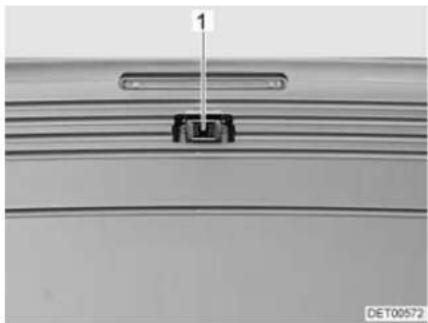
Rear ladder
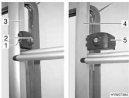
Fig. 1 Rear ladder lock
Folding downwards:
■ Insert the key into the locking cylinder (Fig. 1,2) of the rear ladder lock (Fig. 1,1) and turn it a quarter turn until the key is in a vertical position.
■ Hold the foldable part of the rear ladder (Fig. 1,4) and swing out the securing bracket (Fig. 1,5).
■ Pull out the key and fold the rear ladder downwards.
Folding upwards:
■ Fold the rear ladder upwards and hold it firmly.
■ Insert the key into the locking cylinder (Fig. 1,2) of the rear ladder lock (Fig. 1,1).
■ Swivel the securing bracket (Fig. 1,5) inward around the tube of the fixed part of the rear ladder (Fig. 1,3).
■ Turn the key a quarter turn until it is in a horizontal position.
■ Check the rear ladder lock: Slightly pull on the rear ladder.
4.3.5 Rear garage

▶ Observe the permissible axle loads and maximum permissible gross weight when loading the rear garage.
The maximum permissible load of the rear garage is 200 kg. Do not exceed the permissible rear axle load.
▶ Observe: If the rear garage or (depending on the model) the rear storage space is loaded to its maximum capacity, this will reduce the load on the front axle due to the levering action. The driving quality is impaired.

Depending on the vehicle equipment, clamping rails with clamping eyelets are mounted in the rear garage or in the rear storage space. Always secure loads onto the clamping eyelets. Always use tightening straps or lashing nets for securing the load, never rubber expanders.
When clamping loads, always check that the clamping eyelets are placed tightly in the clamping rails. If the clamping eyelet is not anchored tightly in the clamping rail, the load may slide or loosen during forcible movements of the steering wheel or when braking.
▷ Distribute the load evenly. Excessive spot loads can lead to damages of the floor covering.
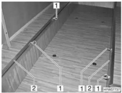
1 Clamping eyelet
2 Clamping rail
Fig. 2 Clamping eyelets rear garage
Moving the clamping eyelets:
■ Turn the clamping eyelet (Fig. 2,1) half a turn in an anticlockwise direction.
■ Push the clamping eyelet into the clamping rail (Fig. 2,2) to the desired position.
■ Give clamping eyelet one half turn in a clockwise direction. The clamping eyelet sits tightly in the clamping rail again.
■ Check that the clamping eyelet is tight.
4.3.6 Double floor

▶ Observe the permissible axle loads and maximum permissible gross weight when loading the double floor.

▷ Distribute the load evenly. Excessive spot loads can lead to damages of the floor covering.
4.3.7 Sliding drawer

Do not place loads weighing more than 40 kg into the sliding drawer.
4.3.8 Bike rack

▶ Observe the permissible axle loads and maximum permissible gross weight when loading the bike rack.
▶ Bicycles may not jut out beyond the maximum width of the vehicle. Adjust the attachments for the bikes accordingly.
▶ Load the bike rack with bicycles only (max. four units).
▶ Check the secure attachment of the bicycles on the bike rack after the first 10 km and then at each break in the journey.

The identification plate and rear lights must not be covered.
▶ Driving with a folded out bike rack without bicycles is not permitted.
▷ Before every journey, check:
Is the bike rack without bicycles folded in correctly?
Are the bicycles securely fastened to the bike rack using the bike rack belts?
Loading the bike rack with bicycles
When loading the bike rack, observe the centre of gravity. The centre of gravity of the bicycles must be as close as possible to the rear wall of the vehicle. The bike rack should always be loaded from the inside to the outside.
Loading the bike rack correctly:
■ Depending on the model, fold the bike rack down or pull it out.
■ Place the heaviest bicycle directly against the rear wall.
■ Place the lightest bicycles in the centre or on the outside of the bike rack.
■ Secure the front and rear wheels of each bicycle with the retaining straps on the bike rack.
In addition, fasten the outermost bicycle depending on the model of the bike rack on the retaining clip or the retaining bracket and to the spacer respectively.
If the bike rack is only loaded with one bicycle, position the bicycle as closely as possible to the rear wall.
4.4 Towing

▶ Care is to be taken when connecting and detaching a trailer. Risk of accident and injury!
▶ No persons are to be between the towing vehicle and the trailer during positioning for connecting and detaching.
▶ Observe the permissible nose weight and rear axle load of the towing vehicle. Nose weight and rear axle load must not be exceeded. The values of the nose weight and rear axle load are included in the documents of the vehicle and the caravan coupling.

▶ Trailer with an overrun brake: Do not connect or detach trailer with the overrun brake on.
Caravan coupling with detachable ball neck: If the ball neck is mounted incorrectly, there is the danger of the trailer breaking away. Observe the instruction manual for the caravan coupling.
4.5 Entrance step

▶ Before commencing the journey and after short interruptions of the journey, ensure that the entrance step is completely retracted.
▶ Do not stand in the direct range of the entrance step while it is being retracted or extended.
▶ Do not step on the entrance step until it has extended completely. There is a risk of injury.
▶ Do not under any circumstances raise or lower persons or loads with the entrance step.

Take note of the different step heights and make certain that the ground is firm and even when exiting.
Do not grease or lubricate the pivot bearing and joints of the entrance step (see chapter 12).
The switch to operate the entrance step is located on the inside of the vehicle in the area of the conversion door.
If the entrance step has not been properly retracted and locked into place, a warning tone is heard when the ignition is switched on.
▶ Follow the warning notice on the entrance step.

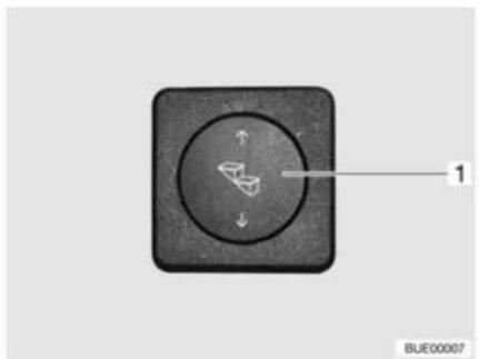
natural_image
Close-up of a black square button with a circular dial and directional arrows, labeled '1' (no text or symbols beyond label)
Fig. 3 Operating switch entrance step Fig. 4 Operating switch for entrance step (alternative)
Before stepping on the entrance step, fully extend it.
Extending:
■ Press lower part of the rocker switch (Fig. 3,1) or press the left switch (Fig. 4,1) until the entrance step has extended completely.
Retracting:
■ Press upper part of the rocker switch (Fig. 3,1) or press the right switch (Fig. 4,2) until the entrance step has retracted completely.
The entrance step can also be retracted and extended with the remote control.
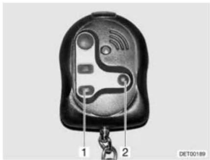
Fig. 5 Remote control for entrance step
Extending:
■ Press the switch (Fig. 5,1) until the entrance step has extended completely.
Retracting:
■ Press the switch (Fig. 5,2) until the entrance step has retracted completely.
Emergency operation
If the electric drive of the entrance step fails, follow the directions below to manually retract the entrance step:
■ Pull out the securing splint from the connection to the engine.
■ Release the rectangular connection to the engine using a suitable object (e.g. a screwdriver).
■ Push in the entrance step by hand and secure it using a suitable device (e.g. a string).
■ Contact customer service.
4.6 PVC-floor covering

Shoes with pointed heels can leave permanent impressions in the PVC-floor covering. Never wear shoes with pointed heels in the vehicle.
Rubber mats or long exposure to ketchup, carrot juice, ink, blood or lipstick can discolour the PVC-floor covering. If possible, remove stains from the floor immediately.
4.7 Television

Before commencing the journey, remove the television from the support and store it securely.
Before commencing the journey, place and secure the flat screen and screen support in the initial position. If the screen holder is installed in a TV cabinet: Close TV cabinet.
Before commencing the journey, ensure that the antenna is in park position. Danger of accidents! Park position means: The antenna points towards the back, is fully lowered and is locked in this position.

▶ Further information on positioning the flat screen can be obtained from chapter 7.
Holder in the TV cabinet The flat screen is attached to a console in the TV cabinet.

Fig. 6 Holder in the TV cabinet
Storing the flat screen:
■ Rotate the flat screen to its initial position and lock it into place.
■ Insert the holder for the flat screen on the handle (Fig. 6,1) until the latch (Fig. 6,2) locks into place.
■ Close TV cabinet.
Holder with jointed arm The flat screen is fastened to a jointed arm.
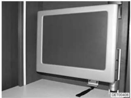
natural_image
Exterior view of a modern flat-screen monitor mounted on a stand, no visible text or symbols on the screen or surroundings.Fig. 7 Holder with jointed arm
Storing the flat screen:
■ Swivel flat screen back to its initial position and lock it into place.
4.8 Sink cover

In the event of an accident or emergency braking, the sink cover (Fig. 8,1) could injure the occupants of the vehicle. Before the journey, take the sink cover off the sink and store it securely in the kitchen unit or wardrobe.
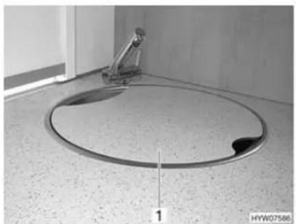
natural_image
Interior view of a bathroom sink with a circular drain and a metal stand (no text or symbols visible)Fig. 8 Sink cover
4.9 Roman shades for driver's window and front passenger's window

▶ While travelling, the Roman shades for the windscreen, driver's window and front passenger's window must be open, in a fixed position and secured.
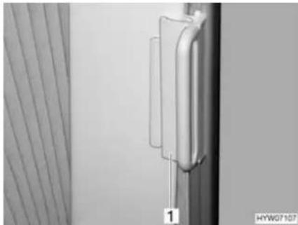
natural_image
Close-up of a metallic mechanical component with a vertical rod and attached bracket, next to a striped curtain (no text or symbols visible)Fig. 9 Locking mechanism for Roman shade on driver's/front passenger's windows
Securing:
■ On the Roman shades for the driver's and passenger's window, push the handle (Fig. 9,1) onto the cap. The Roman shade is secured.
4.10 Central locking system for kitchen unit
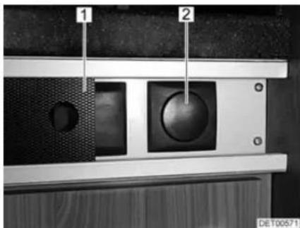
Fig. 10 Switch for the kitchen unit's central locking system
1 Panel
2 Switch for the kitchen unit's central locking system
Depending on the model, the kitchen unit is fitted with a central locking system. The flaps and drawers of the kitchen unit can be locked and unlocked manually via the switch (Fig. 10,2) behind the movable panel (Fig. 10,1).
When you start the vehicle engine, the central locking system is activated automatically.

If a flap or drawer is open when the vehicle's engine is started, it will be locked automatically following closing.
4.11 Snow chains

▶ Only mount snow chains if there is a clearance of at least 50 mm between the tyres and the vehicle body.
When using snow chains, the tyres, wheel suspension and steering are subjected to an additional load. When using snow chains, drive slowly (maximum speed 50 km/h) and only on streets which are completely covered with snow. Otherwise the vehicle could be damaged.
Observe the fitting instructions issued by the manufacturer of the snow chains.
▶ Only use snow chains approved by IVECO.
Do not fit snow chains on alloy wheel rims.

If the drive axle of the vehicle has twin tyres (2 tyres next to each other), mount the the snow chains to the outer tyres.
The snow chains are available at your IVECO dealer.
The use of snow chains is subject to the legal regulations of the individual countries.
● Always mount snow chains to the drive wheels.
● After a few metres, check the tension of the snow chains.
4.12 Road safety

▶ Check tyre pressure before a journey or every 2 weeks. Wrong tyre pressure causes excessive wear and can lead to damage or even to tyre burst. You can lose control of the vehicle.
Before commencing the journey, work through the checklist:
Base vehicle
| No. | Checks Checked | |
| 1 | All vehicle documents are on board | |
| 2 | Tyres in proper condition | |
| 3 | Vehicle lighting, brake lights and reversing lights function | |
| 4 | Oil levels for engine, gearbox and power steering controlled | |
| 5 | Coolant and fluid for windscreen washers filled up | |
| 6 | Brakes function | |
| 7 | Brakes react evenly | |
| 8 | When braking, the vehicle remains in the lane |
Housing body, outside
| 9 Awning completely retracted | |
| 10 Roof free of snow and ice (in winter) | |
| 11 External connections and lines disconnected and stored away | |
| 12 External supports removed | |
| 13 Fitted steady legs retracted and fixed in place | |
| 14 Wheel chocks removed and stored away |
| No. Checks Checked | ||
| 15 Entrance step retracted (observe warning tone) | ||
| 16 External flaps closed and locked | ||
| 17 Conversion door locked | ||
| 18 Overall height of the vehicle including roof rack when loaded measured and noted. Keep the height information close at hand in the driver's cabin | ||
| Housing body, inside | ||
| 19 Windows and skylights closed and locked | ||
| 20 Television secured in the TV cabinet or removed from the support and stored securely | ||
| 21 Television antenna retracted (if one is built in) | ||
| 22 Loose parts stored away or fixed in position | ||
| 23 Open storage spaces empty | ||
| 24 Refrigerator door secured | ||
| 25 All drawers and flaps closed | ||
| 26 Living area doors and sliding doors secured | ||
| 27 Children's seats mounted to seats with three-point safety belts | ||
| 28 Shades in the driver's cabin opened and secured | ||
| Gas system | ||
| Electrical system | ||
Chapter overview
This chapter contains instructions on how to drive the motorhome.
The instructions address the following topics:
- reversing camera
- driving speed
- brakes
- seat belts
- seats and headrests
- seating arrangement
• electrically adjustable external mirrors - sun blinds
- pneumatic spring
- bonnet
● windscreen washer fluid container
• cooling water compensator reservoir - filling the tank
5.1 Driving the motorhome

The base vehicle is a commercial vehicle (small truck). Adjust your driving technique accordingly.
▶ Before commencing the journey and after short interruptions of the journey, ensure that the entrance step is completely retracted.
During the journey, seat belts should always be worn at the seats that have seat belts mounted.
▶ Never open your seat belts when travelling.
▶ Passengers must remain in the seats provided.
▶ The doors must remain locked.
▶ Avoid braking with a jerk.
▶ If a navigation system is used, only change the destination when the vehicle is stationary. Drive to a car park or stop in a safe area when changing the destination.
▶ Do not play DVDs using the monitor of the navigation system during the journey.

▶ Drive slowly on poor roads.
Take extreme care when driving onto ferries, crossing uneven roads and driving in reverse. Because of the relatively large overhang, larger vehicles might swing out and "touch ground" in unfavourable conditions. This can cause damage to the underbody or to parts fitted there.
If an accident occurs as a result of these instructions not being observed, the manufacturer will not be responsible for damages caused.
The safety measures stipulated in chapter 3 have to be observed.
If a reversing camera is installed in the vehicle, the camera is automatically switched on when driving in reverse gear.

5.2 Reversing camera
natural_image
Close-up of a mechanical component with a labeled dimension (1) and identifier (DET00572), no readable text or symbols beyond the label.Fig. 11 Reversing camera
Depending on the model, a reversing camera (Fig. 11,1) with LCD monitor is installed in the vehicle.
The camera and the LCD monitor are switched on automatically when the ignition is switched on or if the vehicle's engine is running and you drive in reverse gear.

Refer to the unit manufacturer's separate instruction manual for details of how to operate the LCD monitor.
5.3 Driving speed

The vehicle is equipped with a powerful engine. This means there are sufficient reserves in difficult traffic situations. This high power enables a high maximum speed and requires above-average driving ability.
The vehicle provides a large contact surface for wind. A sudden cross-wind can be especially dangerous.
▶ Uneven or one-sided loading affects road performance.
- Driving on unknown streets, you may encounter hazardous road conditions and unexpected driving situations. Therefore, in the interest of safety, make sure your driving speed is appropriate to any given driving situation and environment.
▶ Adhere to the national legal speed limits.
5.4 Brakes

▶ Have defects on the braking system immediately remedied by an authorised specialist workshop.

Avoid block braking. Block braking gives the tyres "brake plates" of varying strength. This reduces driving comfort. It might even make the tyres unserviceable.
Before each journey Before each journey, check by means of a braking test:
- Do the brakes function?
- Do the brakes react evenly?
- Does the vehicle remain in the lane when braking?
5.5 Seat belts
The vehicle is equipped with automatic three-point safety belts in the living area on the seats for which seat belts are compulsory by law. National regulations apply seat-belt fastening.

▶ Fasten your seat belts before the beginning of the journey and keep them fastened during the journey.
▶ Do not damage or trap belts. Have damaged seat belts changed by an authorised specialist workshop.
▶ Do not alter the belt fixing devices, automatic seat belt winders and the belt clips.
Inspect the screwed connections of the seat belts from time to time in order to ensure that they are correctly seated.
▶ Only use one seat belt for one adult person.
▶ Do not belt in objects together with persons.
▶ Seat belts are not sufficient for persons who are less than 150 cm tall. In these cases use additional restraining devices. Observe test certificate.
▶ Factory-set three-point safety belts must be used when attaching child restraint systems.
▶ After an accident, replace the seat belts.
During the journey, do not tilt the backrest too far backwards. Otherwise the functionality of the seat belt is no longer guaranteed.
5.5.1 Fastening the seat belt correctly

▶ Do not twist the belt. The belt must be positioned smoothly against the body.
▶ When fastening the seat belt, adopt the correct sitting position.
The seat belt is fastened correctly when a fist can be passed between the body and the seat belt.
5.6 Driver's seat and front passenger's seat

Before commencing the journey, rotate all swivel seats in the direction of travel and lock in position.
The seats must remain fixed in position during the journey and are not to be rotated.

The driver's and front passenger's seat are a part of the base vehicle, depending on model and vehicle equipment. In this case the adjustment of the seats is described in the operating instructions of the base vehicle.
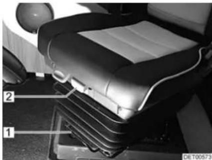
natural_image
Interior view of a car seat with labeled parts (1 and 2), no visible text or symbols beyond labelsFig. 12 Operating controls in front of the seat
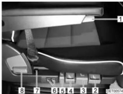
Fig. 13 Operating controls next to the seat
Rotating seat into driving position
The seats can be rotated in any direction. The seats can only be locked in position in the direction of travel.

■ Push both armrests upward.
■ Push the seat backwards or into the central position.
■ Rotate the seat in the direction of travel and lock in position.
▶ Rotating the seats in the pitched vehicle is described in chapter 7.
Adjusting seat in lengthways direction
Adjust the driver's seat so that the driver can depress the pedals comfortably.
■ Pull the bar (Fig. 12,1) upwards.
■ Push the seat forwards or backwards.
■ Release the bar. The seat must audibly lock into place.
Adjusting the seat depth Adjust the seat so that the thighs rest on the seat surface.
Setting the seat inclination
■ Pull the handle (Fig. 12,2) upwards.
■ Push the seat forwards or backwards.
■ Release handle. The seat must audibly lock into place.
Adjust the seat inclination so that the thighs rest on the seat surface without any pressure.
■ Pull the handle (Fig. 13,3) upwards.
■ Bring the seat into the desired inclination position by applying or relieving pressure.
■ Release handle. The seat must audibly lock into place.
Adjusting the seat height
Adjust the seat height so that the thighs rest on the seat without pressure and the driver can depress the pedals comfortably.
■ If the seat should move up: Pull the handle (Fig. 13,4) upwards.
■ If the seat should move down: Push the handle down (Fig. 13,4).
■ If the seat should be lowered quickly: Push the handle down (Fig. 13,5). The seat moves into the lowest position.
■ If the seat should move into its normal position after quick lowering: Pull the handle (Fig. 13,5) upwards.
Adjusting the cushioning

The cushioning can be steplessly adjusted from "soft" to "hard".
▶ Always adjust the cushions on the driver's seat so that the feet are always in contact with the pedals, even when the road surface is poor.
■ Pull the handle (Fig. 13,2) upwards. The cushioning becomes "softer".
■ Push the handle down (Fig. 13,2). The cushioning becomes "harder".
The air spring adjusts itself automatically to the person's weight.

Adjusting the backrest
Adjust the angle of the backrest so that the steering wheel can be held with the arms slightly bent.
■ Pull the handle (Fig. 13,8) upwards.
■ Bring the backrest into the desired inclination position by applying or relieving pressure.
■ Release handle. The backrest must audibly lock into place.
Adjusting the lumbar support
The chambers of the lumbar support can be adjusted separately.
■ Press the upper part of the switch (Fig. 13,6). The air chamber fills.
■ Press the lower part of the switch (Fig. 13,6). The air chamber empties.
Adjusting the armrest The height of the armrests can be steplessly adjusted.
■ Turn the knurled wheel (Fig. 13,1). The armrest inclines upwards or downwards, depending on the rotation direction.
Switching on the seat heater
The seat heater can be adjusted in two stages.
■ Press the front part of the switch (Fig. 13,7). The seat heater is on. The LED on the switch lights up.
■ Press the rear part of the switch (Fig. 13,7). The seat heater is switched to fast heating. The LED on the switch lights up.
5.7 Headrests

The headrests are not adjustable for all models.
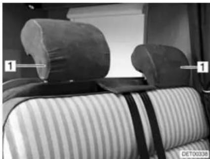
natural_image
Interior view of a car backrest with two side pillows and striped bedding (no visible text or symbols)Fig. 14 Bench headrest
Before commencing the journey, adjust the headrests (Fig. 14,1) so that the back of the head is supported at approximately ear height. Push the headrests upwards or downwards by hand.
5.8 Seating arrangement

During the journey, persons are only to sit on the permitted seats. The authorised number of seats is stipulated in the vehicle documents.
▶ During the journey sitting on the divans is not permitted.
▶ Seat belts must be worn by all passengers.
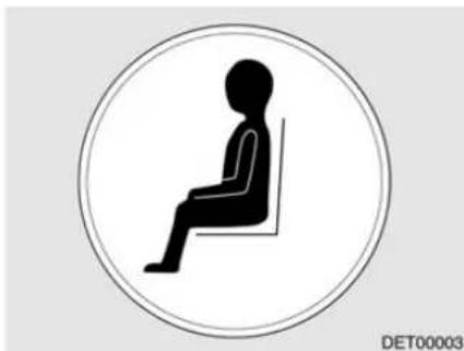
natural_image
Silhouette of a seated person in a chair inside a circle (no text or symbols)Fig. 15 "Seat" symbol
Seats which may be used during travel are equipped with a sticker (Fig. 15).
5.9 Electrically adjustable external mirrors
Depending on the model, the vehicle is equipped with two electrically adjustable and heated external mirrors. The switches for external mirror adjustment and the mirror heater are on the dashboard.
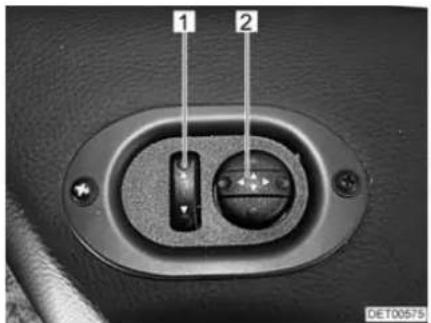
Fig. 16 Switch for electrically adjustable external mirrors
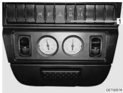
natural_image
Front view of a car dashboard with air gauges and control buttons (no readable text or symbols)Fig. 17 Switch for mirror heater
Adjusting:
■ Select the mirror to be adjusted. To do so, push the flip switch (Fig. 16,1) to the left or right.
■ Adjust the mirror by pressing the switch (Fig. 16,2) in the appropriate direction.
■ Press the switch (Fig. 17,1) on the dashboard. The switch indicator lamp shows it is in operation.
5.10 Sun visors
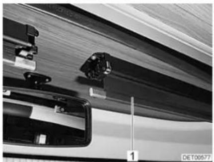
natural_image
Close-up of mechanical components and a vehicle's side profile, no visible text or symbolsFig. 18 Sun visor Fig. 19 Sun visor switch
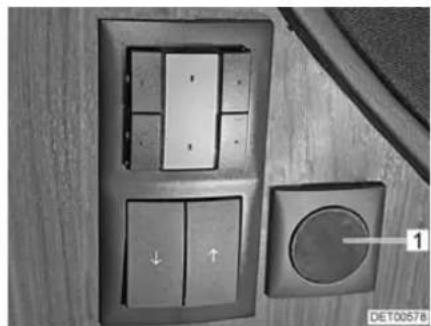
natural_image
Close-up of a wall-mounted control panel with buttons and a circular dial, no visible text or symbolsDepending on the model, the vehicle has two electrically operated sun visors (Fig. 18,1).
The switches for operating the sun visors are each installed in outside of the panelling on the left and right.
Extending the sun visor:
■ Press the lower part of the switch (Fig. 19,1). The sun visor moves down.
■ When the desired position is reached or the sun visor has been completely extended: Release the switch.
Retracting the sun visor:
■ Press the upper part of the switch (Fig. 19,1). The sun visor moves up.
■ When the desired position is reached or the sun visor has been completely retracted: Release the switch.
5.11 Pneumatic spring
5.11.1 Pneumatic spring (Goldschmidt)

▶ Only drive at a steady, low speed if there is a fault with the pneumatic spring and have the fault immediately repaired by an authorised specialist workshop.
▶ Do not allow children to play with the system.
The compressor becomes very hot during operation. Do not touch the compressor during operation and for a short time after operation.

▶ Only operate the system when the vehicle is stationary and the engine is running.
Do not exceed the maximum permissible pressure of 9 bar (130 PSI).
▶ Further information can be obtained in the manufacturer's instruction manual.

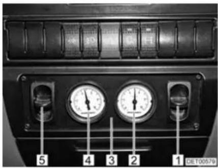
Fig. 20 Control unit for pneumatic spring
1 Operating switch for pneumatic springs (circuit 1)
2 Pressure gauge (circuit 1)
3 Control unit
4 Pressure gauge (circuit 2)
5 Operating switch for pneumatic springs (circuit 2)
The pneumatic springs of circuits 1 and 2 can be controlled separately via the operating switches (Fig. 20,1 and 5).
Increasing the pressure in the pneumatic springs:
■ Press up the operating switch (Fig. 20,1 or 5) on the control unit (Fig. 20,3). When doing so, monitor the pressure on the pressure gauge (Fig. 20,2 or 4).
■ Press down the operating switch (Fig. 20,1 or 5) on the control unit (Fig. 20,3). When doing so, monitor the pressure on the pressure gauge (Fig. 20,2 or 4).
Reducing the pressure in the pneumatic springs:
Overheating protection
The system has automatic overheating protection. When the overheating protection responds, allow the system to cool down for at least 30 minutes.
5.11.2 Pneumatic spring (VB-air suspension)

▶ Only drive at a steady, low speed if there is a fault with the pneumatic spring and have the fault immediately repaired by an authorised specialist workshop.
▶ Only operate the remote control, if people or objects are not in the working area under the vehicle.
▶ Do not allow children to play with the system.
The compressor becomes very hot during operation. Do not touch the compressor during operation and for a short time after operation.

▶ Only raise or lower the vehicle when parked.
Before raising or lowering, always apply the handbrake and put the gear into the neutral position ("take out" gear).
- Depending on the model, not all the functions described here are available at all times.
- Further information can be obtained in the manufacturer's instruction manual.

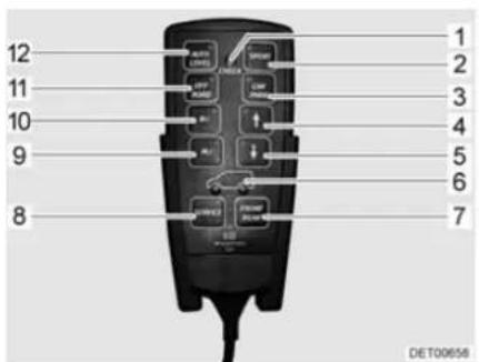
1 Indicator lamp
2 Sport function button
3 Parking function button
4 Raise button
5 Lower button
6 Axle selection display
7 Axle selection button
8 Service button
9 Saved level 2 button
10 Saved level 1 button
11 Off road function button
12 Levelling function button
Fig. 21 Remote control
The pneumatic spring provides the vehicle with fully automatic levelling control.
Various pneumatic spring functions can also be switched manually via the buttons on the remote control. The increase of ground clearance simplifies e.g. driving onto ferries (bigger gradient angle) or driving on rough terrain.
A short beeping tone is sounded when a button is pressed.

All button functions are available only if the ignition has been switched on and the engine is running. In addition, the button functions remain available for 1 hour after the ignition has been switched off (run-down time).
The following functions can be selected via the buttons:
| Button Function | |
| SPORT(Fig. 21,2) | Switching sport function on and off.When the sport function is activated, the vehicle is lowered and its driving stability is increased. |
| CAR PARK(Fig. 21,3) | Switching parking function on and off.When the parking function is activated, the vehicle is lowered to the lowest possible level. This simplifies e.g. driving into a garage with a low clearance height.⚠️ ▶ When this function is activated, never drive faster than 25 km/h. When this speed is exceeded, the function is automatically deactivated and the vehicle is raised to the normal level. |
| ↑(Fig. 21,4) | Raising the vehicle.Possibility A: Press the button briefly in order to raise the vehicle to one of the three levels that have been preprogrammed at the factory.Possibility B: Press button until the required level or the highest position is reached. |
| ↓(Fig. 21,5) | Lowering the vehicle.Possibility A: Press the button briefly in order to lower the vehicle to one of the three levels that have been preprogrammed at the factory.Possibility B: Press button until the required level or the lowest position is reached. |
| FRONT REAR(Fig. 21,7) | Axle selection.Possibility A: Press the button briefly in order to change between the pneumatic spring for the front axle and the one for the rear axle.Possibility B: Press the button for longer in order to change to the pneumatic spring of both axles.The blue lamps in the wheels of the illustrated vehicle (Fig. 21,6) show which axle is activated for operation. |
| SERVICE(Fig. 21,8) | Activating or deactivating the system or ending the run-down time. |
| M1 (Fig. 21,10)M2 (Fig. 21,9) | Raising or lowering to the saved level. Press the button briefly to do this.Save:Bring the vehicle to the desired level using the buttons " ↑ and " ↓Keep the memory button "M1" or "M2" pressed until a long beeping tone is sounded.The selected level has been saved. |
| OFF ROAD(Fig. 21,11) | Activating and deactivating the off road function.When the off road function is activated, the vehicle is raised to give it more ground clearance. |
| AUTO LEVEL(Fig. 21,12) | Activating and deactivating the levelling function.When the levelling function is activated, the vehicle is aligned horizontally (e.g. on an uneven parking site).If you drive with the levelling function activated, the function is automatically switched off when a speed of 8 km/h is exceeded, and the vehicle is adjusted to the normal level. |
The indicator lamps in the buttons and on the remote control show the operating states of the individual functions.
| LED Signification | Status | |
| Blue or green LED in the function button | Off Function inactive | |
| Flashing The system is carrying out the selected function | ||
| Illuminated The selected function is active | ||
| Red LED in the service button | Off Function inactive | |
| Illuminated Function active. The system is deactivated | ||
| Red LED "CHECK" | Off The system is operating without faults | |
| Lights up briefly | The system has started up without any problems | |
| Flashing There is a fault in the system. For troubleshooting, see the section 15.2.2 | ||
5.12 Bonnet

When the bonnet is open, there is a risk of injury in the engine compartment.
Even if the engine was switched off some time ago, it might still be hot. Danger of burns!
▶ Do not work in the engine compartment while the engine is running.
The bonnet must be kept firmly closed and locked during the journey. After closing, check whether the lock has engaged. In order to carry this out, pull on the bonnet.
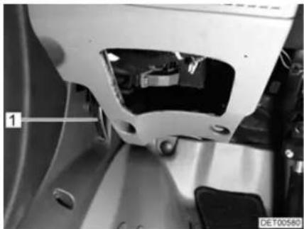
natural_image
Close-up of a mechanical component with labeled part '1' and identifier 'DE700580' (no readable text or symbols beyond labels)Fig. 22 Release lever on the inside of the bonnet
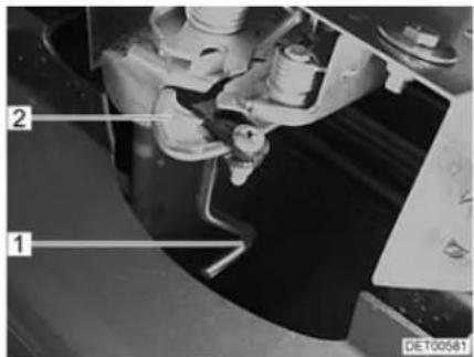
Fig. 23 Release lever on the outside of the bonnet
Opening:
■ Pull the lever (Fig. 22,1) situated on the left-hand side of the vehicle under the dashboard. The bonnet opens as far as the safety hook allows.
■ Reach under the bonnet with one hand and actuate the safety hook (Fig. 23,2). To do this, turn the extension (Fig. 23,1) in an anticlockwise direction.
■ Move the bonnet in an arch forwards and downwards.
Closing:
■ Move the bonnet in an arch upwards and backwards until the latch engages audibly in place.
■ Check whether the bonnet is locked correctly. In order to carry this out, pull on the bonnet.
5.13 Filling with washer fluid
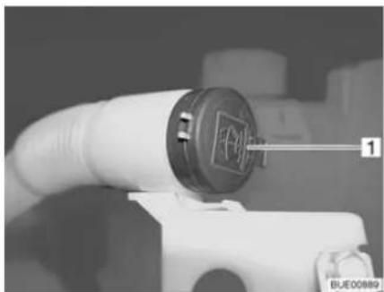
natural_image
Close-up of a white spray gun with a circular cover and label '1' pointing to its side (no readable text or symbols on the gun itself)Fig. 24 Washer fluid container filler neck
■ Unlock and open the bonnet.
■ Remove the lid (Fig. 24,1) from the filler neck of the washer fluid container.
■ Slowly fill in washer fluid.
■ Push the lid onto the filler neck of the washer fluid container.
5.14 Refilling cooling water

▶ Allow the coolant to cool down before opening the cooling system. Risk of scalding!
▶ Allow the cooling system to cool down before opening. The cooling system is under high pressure when it is hot. There is a risk of injury.
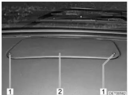
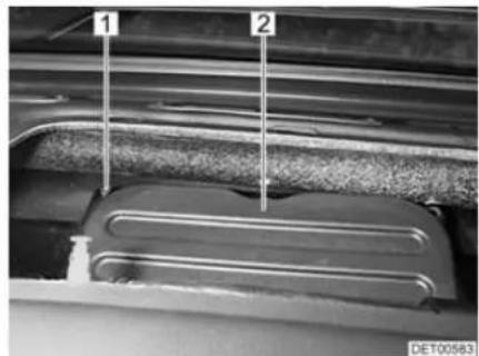
natural_image
Close-up of a metallic component with two labeled parts (1 and 2), no visible text or symbols beyond labelsFig. 25 Cover in the dashboard Fig. 26 Engine compartment cover
■ Loosen the two screws (Fig. 25,1) and take off the cover (Fig. 25,2).
■ Unscrew six hexagon socket screws (Fig. 26,1) and remove them with the washers.
■ Remove cover (Fig. 26,2).
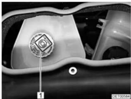
natural_image
Close-up of a mechanical component with a circular emblem and numbered label (1), no readable text or symbols beyond the label.Fig. 27 Cover on the cooling water compensator reservoir
■ Open the cover (Fig. 27,1) carefully and allow the pressure to escape.
■ Remove the cover and top up with cooling water from a suitable vessel (e.g. a bottle).
■ Screw the cover (Fig. 27,1) back onto the cooling water compensator reservoir.
■ Screw both covers (Fig. 26,2 and Fig. 25,2) securely back in place.
5.15 Filling up with diesel

▶ No appliance operated by a naked flame (e.g. heater or refrigerator) may be in operation when filling the tank, on ferries or in the garage. Danger of explosion!

Depending on the model, the fuel filler neck is part of the base vehicle. In this case, filling the tank is described in the operating manual of the base vehicle.
The fuel filler neck is labelled with the word "Diesel".
The fuel filler neck is situated on the exterior of the vehicle, at the front left.
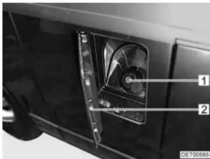
Fig. 28 Cap for the fuel filler neck
Opening:
■ Swivel the flap (Fig. 28,2) to the side.
■ Insert the key in the locking cylinder (Fig. 28,1) and turn it in an anticlockwise direction.
■ Remove the cap.
Closing:
■ Place the cap on the fuel filler neck.
■ Turn key in a clockwise direction.
■ Remove the key.
■ Check that the cap is fastened securely on the fuel filler neck.
■ Close flap.
Chapter overview
This chapter contains instructions on how to pitch the vehicle.
The instructions address the following topics:
- handbrake
- entrance step
- wheel chocks
• operation of the supports - 240 V connection

▶ Pitch the vehicle so that it is as horizontal as possible. Secure the vehicle to prevent it from rolling.
Animals (especially mice) can cause great damage to the interior of the vehicle. To prevent this from happening, regularly check the vehicle for damages or animal traces after pitching.
6.1 Handbrake
Firmly apply the handbrake when parking the vehicle.

If there is any risk of frost, release the handbrake every now and then and apply it again. This will prevent it from freezing or rusting. Prior to releasing the handbrake, secure the vehicle so that is cannot roll away.
6.2 Entrance step
In order to exit the vehicle, first fully extend the entrance step.
6.3 Wheel chocks
When parking the vehicle on slopes or inclines use the wheel chocks.
If the maximum permissible gross weight of the vehicle exceeds 4 tonnes, wheel chocks must be used when parking on gradients. The wheel chocks are provided as standard for vehicles with a maximum permissible gross weight exceeding 4 tonnes.
6.4 Supports
6.4.1 General instructions

Do not use the fitted supports as a vehicle jack. They supports are only for stabilising the parked vehicle to prevent the rear axle from bottoming out.
▷ When pitching the vehicle, ensure that the supports are evenly loaded.
Before driving away, wind up the supports as far as they can go, fully retract and secure them.
When the ground is soft, place a pad or block under the supports in order to prevent the vehicle from sinking into the ground.

6.4.2 Steady legs

Make sure that all steady legs are retracted completely and that the guide disc for each steady leg has been completely retracted into the notch.
In order to ensure their correct function, clean and grease the interior tubes of the steady legs regularly.
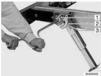
natural_image
Close-up of a hand using a tool to adjust or install a mechanical component, labeled with numbers 1, 2, and 3 (no text or symbols on the device itself)Fig. 29 Steady leg
Extending:
■ Place the socket spanner on the hexagon nut (Fig. 29,1) and rotate. The steady leg swings downward and is automatically extended.
■ Rotate the hexagonal nut until the steady leg rests completely on the ground and the motorhome is in a horizontal position.
Retracting:
■ Place the socket spanner on the hexagon nut (Fig. 29,1) and rotate until the steady leg is clear of the ground.
■ Rotate the hexagonal nut with the socket spanner until the steady leg has swung upwards and the guide disc (Fig. 29,3) has completely retracted into the notch (Fig. 29,2).
6.4.3 Electrical steady legs

The engine can then also be left on (to charge the batteries) if the steady legs are extended. Before moving off, always check that the steady legs are retracted completely (observe warning light and warning tone).
▶ Only extend and retract the steady legs if the areas around the legs are totally clear of obstacles.

Steady legs need sufficient ground clearance to be able to fold out vertically.
▷ Before operating the steady legs, release the handbrake.

▶ Further information can be obtained in the manufacturer's instruction manual.
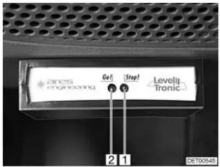
Fig. 30 Display Fig. 31 Remote control

LED indicator
| LED indicator | Signification |
| Green LED (Fig. 30,2) on | Steady legs retracted completely, system ready to operate |
| Green LED (Fig. 30,2) on, red LED (Fig. 30,1) on | Steady legs extended, system ready to operate |
Button functions
| Button Function | |
| UP(Fig. 31,6) | Retract steady leg (Start/Stop)< 1 second = single steady leg> 1 second + button "1" = two steady legs |
| DOWN(Fig. 31,1) | Extend steady leg (Start/Stop)< 1 second = single steady leg> 1 second + button "2" = all four steady legs |
| 1(Fig. 31,5) | Front steady leg, left< 1 second = selects steady leg> 1 second + button "2" = automatic levelling> 1 second + "UP" button = retracts two steady legs |
| 2(Fig. 31,2) | Front steady leg, right< 1 second = selects steady leg> 1 second + "DOWN" button = extends all steady legs |
| 3(Fig. 31,4) | Rear steady leg, left< 1 second = selects steady leg> 8 seconds + button "4" = activates the system after system shutdown |
| 4(Fig. 31,3) | Rear steady leg, right< 1 second = selects steady leg> 8 seconds + button "3" = activates the system after system shutdown |
Activating:
■ Park vehicle on even and stable ground and secure against rolling.
■ Switch on ignition. Green LED (Fig. 30,2) flashes for approx. 6 seconds, acoustic signal sounds.
■ Check LED indicator.
Extending: ■ Select steady leg.
■ Briefly press the "DOWN" button (Fig. 31,1). Steady leg swings downwards and extends.
■ Shortly before the steady leg reaches the ground, press the "DOWN" button again. The procedure is stopped.
■ Extend all four steady legs in the same way.
■ Press buttons "1" (Fig. 31,5) and "2" (Fig. 31,2) for a few seconds. Vehicle is automatically aligned horizontally.
■ Check if all the steady legs are touching the ground.
■ If necessary, select a steady leg and extend to the ground with the "DOWN" button.
Retracting: ■ Select steady leg.
■ Briefly press the "UP" button (Fig. 31,6). Steady leg retracts and swings upwards. When the end position has been reached, the system stops automatically.
■ Retract all four steady legs in the same way.
Emergency operation:
■ Secure the vehicle to prevent it from rolling.
■ Lift vehicle using the vehicle jack until the steady leg is clear of the ground.
■ Move steady leg back and fix to chassis.
■ Contact customer service.
6.4.4 Electrical-hydraulic steady legs

The engine can be started (in order to charge the batteries) even if the steady legs are extended. Before moving off, always check that the steady legs are retracted completely (observe warning light and warning tone).
▶ Only extend or retract the steady legs if the lifting area and the area around the legs are clear of obstacles.
There must be no persons or animals close by when the system is in operation. The system is under high pressure. Escaping fluids can cause serious injury.

▷ Always apply the handbrake before operating the steady legs.
▷ Persons or animals inside the vehicle must remain still while the steady legs are being extended. Otherwise, the controller mechanism will be disturbed.
▶ Further information can be obtained in the manufacturer's instruction manual.

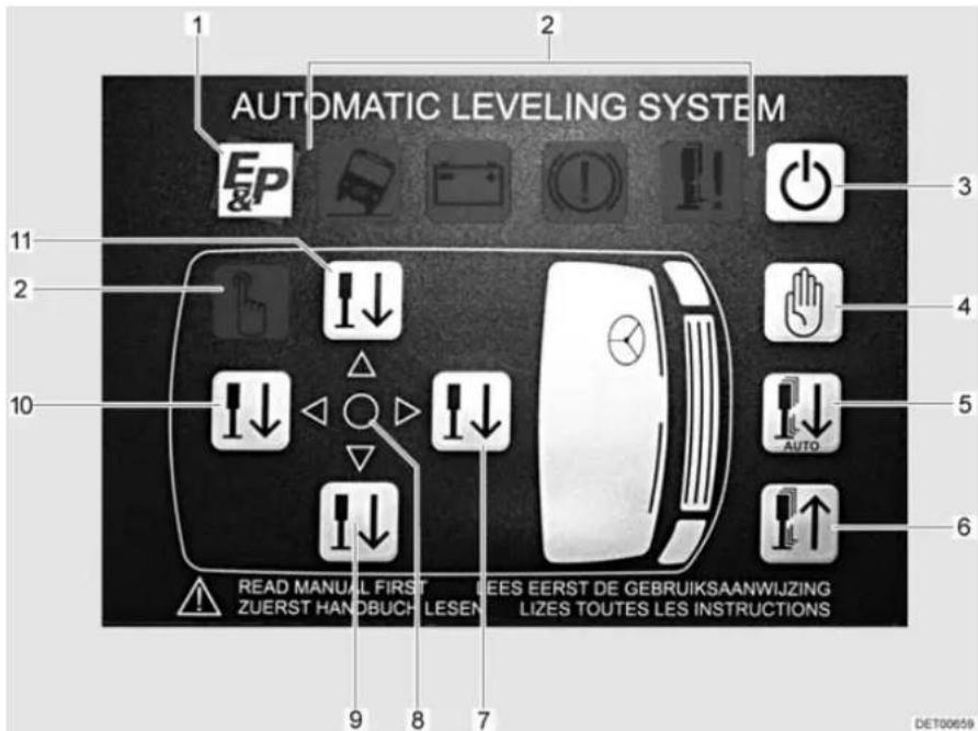
Fig. 32 Control unit, steady legs
1 Company logo
2 LED indicators (symbols)
3 On/Off switch
4 Manual operation button
5 Automatic operation button
6 Retract steady legs button
7 Front side button
8 Level LED
9 Right side button
10 Rear side button
11 Left side button
LED indicators
The LED indicators (Fig. 32,2) are only visible when the respective situation occurs. The following situations are indicated:
● Vehicle tilted too much (vehicle symbol)
● Battery voltage too low (battery symbol)
● Handbrake not applied (brake symbol)
● Steady leg not fully retracted (steady leg symbol)
● Manual operation activated (hand symbol)
Operation The steady legs can be extended manually or automatically. The zero point must be set prior to automatic extension.
Activating:
■ Park vehicle on even and stable ground and secure against rolling.
■ Apply the handbrake.
■ Switch on ignition.
Setting the zero point:
■ Align the vehicle manually using a spirit level.
■ Press the On/Off switch (Fig. 32,3).
■ Press the front side button (Fig. 32,7) five times.
■ Press the rear side button (Fig. 32,10) five times. All LEDs flash.
■ Press the retract steady legs button (Fig. 32,6) three times and wait for 20 seconds. The zero point is now saved.
Extending the steady legs automatically:
■ Activate the system.
■ Press the On/Off switch (Fig. 32,3). The LED with the company logo (Fig. 32,1) lights up.
■ Press the automatic operation button (Fig. 32,5). When the green level LED (Fig. 32,8) lights up, the support process has been completed.
■ Press the On/Off switch (Fig. 32,3) to switch off the system.
▷ Always steady the vehicle at the front first.

Extending the steady legs manually:
■ Activate the system.
■ Press the On/Off switch (Fig. 32,3).
■ Press the manual operation button (Fig. 32,4) until the LEDs in the direction arrows light up.
■ Press the front side button (Fig. 32,7) until the steady legs reach the ground.
■ Press the rear side button (Fig. 32,10) until the steady legs reach the ground.
If the arrow is pointing towards the front side of the vehicle: Press the front side button (Fig. 32,7) until the arrow goes out.
If the arrow is pointing towards the rear side of the vehicle: Press the rear side button (Fig. 32,10) until the arrow goes out.
■ If the arrow is pointing towards the left side of the vehicle: Press the left side button (Fig. 32,11) until the arrow goes out and the level LED (Fig. 32,8) lights up.
If the arrow is pointing towards the right side of the vehicle: Press the right side button (Fig. 32,9) until the arrow goes out and the level LED (Fig. 32,8) lights up.
■ Press the On/Off switch (Fig. 32,3) to switch off the system.
Retracting the steady legs:
■ Press the On/Off switch (Fig. 32,3).
■ Briefly press the retract steady legs button (Fig. 32,6) (automatic operation) or keep it pressed until the steady legs are fully retracted (manual operation).
■ Press the On/Off switch (Fig. 32,3) to switch off the system.
■ Check whether all steady legs are fully retracted.
6.5 240 V connection
The vehicle can be connected to a 240 V power supply (see chapter 9).
6.6 Awning

▷ Retract the awning in strong wind, rain or snow.
In the case of light rain, shorten one of the support legs so that water can run off.
Only retract the awning when the fabric is dry. When the awning must be retracted while the fabric is still wet: Extend the awning as soon as possible, in order to dry out the fabric.
Before retracting, remove leaves and coarse dirt from the awning.

▶ Only use the awning for protection against the sun.
Also read the manufacturer's instruction manual.
Advantages of the awning The advantages of an awning are:
• The awning provides shade.
- The awning creates a covered vestibule and thus expands the space.
- The vehicle thus becomes more homelike.
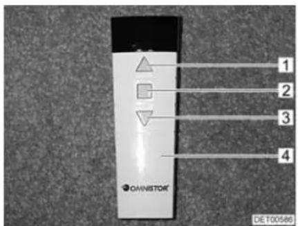
1 Retracting
2 S t o p
3 Extending
4 Remote control
Fig. 33 Remote control
Putting up the awning:
■ Press the button (Fig. 33,3) on the remote control (Fig. 33,4). The awning extends.
■ When the awning is extended: Set up the brackets.
Retracting the awning:
■ Fold in the brackets.
■ Press the button (Fig. 33,1) on the remote control (Fig. 33,4). The awning retracts.
The movement of the awning can be stopped with the Stop button (Fig. 33,2).

Chapter overview
This chapter contains instructions about living in the vehicle.
The instructions address the following topics:
- opening and closing the doors, the external flaps and the driver's cabin partition
● ventilation of the vehicle - opening and closing the windows and blinds
- opening and closing the shades in the driver's cabin
- opening and closing the skylights
- rotating the seats
- modifying the table surfaces
- converting tables
- operating the central locking on the kitchen unit
- positioning the television
- lamps
- light switches
- light control
● remote control for lighting and entrance step
• extending the seating groups - use of the beds
7.1 Doors


▶ Only drive with locked doors.
- Locking the doors can prevent them from opening of their own accord, e.g. during an accident.
- Locked doors also prevent forced entry, e.g. when waiting at traffic lights. However, in an emergency, locked doors make it more difficult for helpers to enter the vehicle.
▷ When leaving the vehicle, always lock the doors.
Depending on the model, the locks of the driver's and the front passenger's doors are part of the base vehicle. In this case, the opening and closing of the driver's door and the front passenger's door is described in the operating manual of the base vehicle.
7.1.1 Conversion door, outside
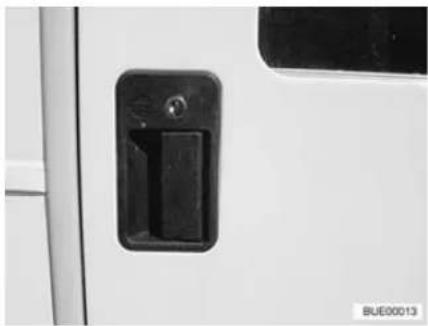
natural_image
Close-up of a white door with a black handle and two buttons, no visible text or symbolsFig. 34 Door lock of conversion door, outside
Opening: ■ Insert the key into locking cylinder and turn until the door lock is unlatched.
■ Return the key to the central position and remove it.
■ Pull on the handle. The door is open.
Locking: ■ Insert the key into locking cylinder and turn until the door lock is engaged.
■ Return the key to the central position and remove it.
7.1.2 Conversion door, outside (Hartal)
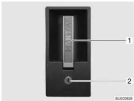
Fig. 35 Door lock of conversion door, outside
Opening: ■ Insert the key into locking cylinder (Fig. 35,2) and turn until the door lock is unlatched.
■ Return the key to the central position and remove it.
■ Pull on the handle (Fig. 35,1). The door is open.
Locking: ■ Insert the key into locking cylinder (Fig. 35,2) and turn until the door lock is engaged.
■ Return the key to the central position and remove it.
7.1.3 Conversion door, inside
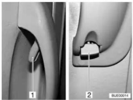
natural_image
Medical illustration showing two views of a joint with labeled parts (1 and 2), no text or symbols present.Fig. 36 Door lock of conversion door, inside, open
Opening: ■ Push the handle (Fig. 36,1).
Locking: ■ Push the lever (Fig. 36,2) down.
7.1.4 Conversion door, inside (Hartal)
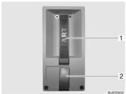
Fig. 37 Door lock of conversion door, inside
Opening: ■ Pull on the handle (Fig. 37,1). The door lock is unlatched.
Locking: ■ Turn the safety knob (Fig. 37,2) in a clockwise direction.
7.1.5 Window conversion door
The conversion door window is fitted with an insect screen and blind.
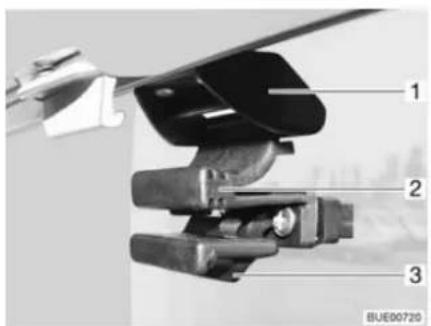
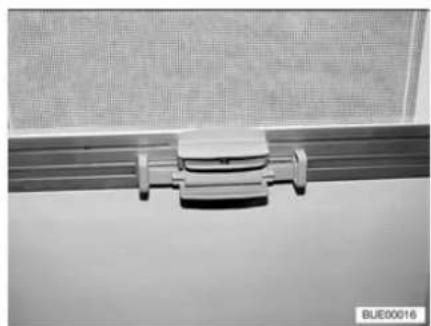
natural_image
Close-up of a metallic mechanical component mounted on a flat surface, with no visible text or symbols.Fig. 38 Window in the conversion door Fig. 39 Blind
Opening the window:
■ Press the retainer (Fig. 38,3) back.
■ Press the handle (Fig. 38,2) together and push the window down.
Closing the window:
■ Push the window up until the handle (Fig. 38,2) engages in the lock (Fig. 38,1).
Insect screen To close and open the insect screen:
Closing:
- Grasp the bottom rod of the insect screen and guide it to the bottom rod of the blind.
■ Lock catch in place.
■ Continuous adjustment of the blinds may be made by moving the bottom rods.
Opening:
■ Hold the bottom rod of the insect screen and activate the catch.
■ Return the bottom rod of the insect screen to the limit stop on the screen.
7.1.6 Window of conversion door (Hartal)
The conversion door window is fitted with a Roman shade.
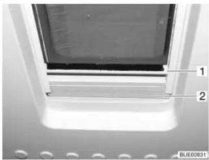
Fig. 40 Roman shade
Closing:
- Grip the Roman shade (Fig. 40,2) in the middle of the bar (Fig. 40,1), pull it upwards and then release it at the desired height. The Roman shade will stay at this height.
Opening:
■ Grip the Roman shade in the middle of the bar and push it down.
7.1.7 Folding insect screen on the conversion door
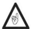
▷ Open the insect screen completely before closing the conversion door.
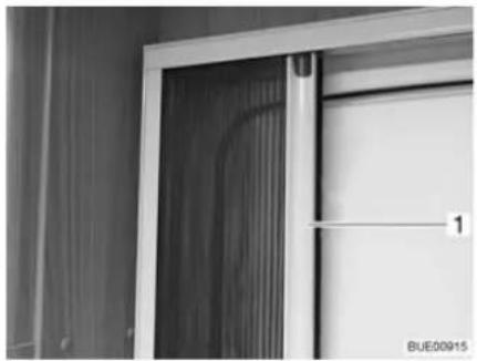
natural_image
Close-up of a door frame with ventilation duct and a numbered label (1), no readable text or symbols beyond the label.Fig. 41 Insect screen
Closing: ■ Pull out the insect screen completely by the bar (Fig. 41,1).
Opening: ■ Push the insect screen into its initial position by the bar (Fig. 41,1).
7.2 External flaps

Before commencing the journey, close all external flaps and lock them. To open and close the external flap, open or close all locks that are fitted to the external flap.

▷ When leaving the vehicle, close all external flaps.
The external flaps fitted to the vehicle are all fitted with identical locking cylinders. Therefore, all locks can be opened with a single key.
7.2.1 Flap lock with recessed handle

To open the external flap, pull all the lock handles fitted to that particular external flap at the same time.
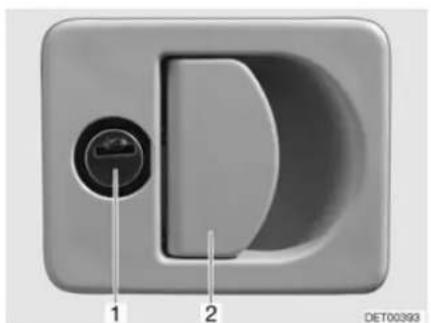
natural_image
Close-up of a D-shaped electronic device with labeled ports (no text or symbols beyond labels)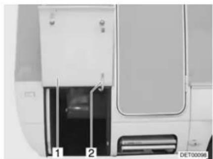
natural_image
Exterior view of a white vehicle door with two labeled parts (1 and 2), no visible text or symbols on the main body.Fig. 42 Flap lock with recessed handle Fig. 43 External flap, open
Opening: ■ Insert key into locking cylinder (Fig. 42,1) and turn a quarter turn. The flap lock is unlatched.
■ Remove the key.
■ Pull on the lock handle (Fig. 42,2). The external flap is open.
■ Swivel the external flap upwards and hold it.
■ Pull out the lever (Fig. 43,2) and turn it upwards a quarter turn.
■ Lean the external flap (Fig. 43,1) against the lever.
Closing:
■ Hold the external flap (Fig. 43,1).
■ Turn the lever (Fig. 43,2) down a quarter turn and push it in.
■ Firmly close the external flap.
■ Insert key into locking cylinder and turn a quarter turn. The flap lock is locked.
■ Remove the key.
7.2.2 Flap lock with separate locking cylinder
In the case of models fitted with central locking systems, the flap lock is connected to the central locking system.
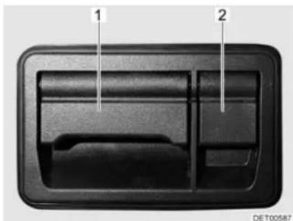
natural_image
Interior view of a car air vent or intake manifold with labeled parts (1 and 2), no visible text or symbols beyond labels.Fig. 44 Flap lock with separate locking cylinder
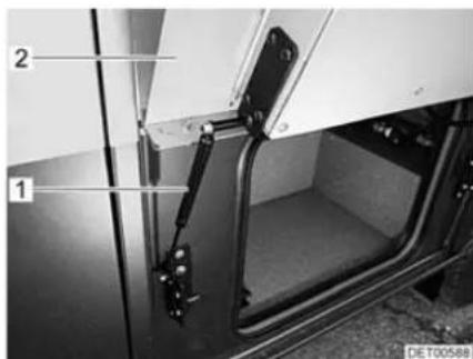
Fig. 45 External flap, open
Opening:
■ Pull on the lock handle (Fig. 44,1). The external flap swings up and is held in place by the gas pressure spring (Fig. 45).
Proceed as follows when the external flap is locked:
■ Fold up the cover (Fig. 44,2).
■ Insert key into locking cylinder and turn a quarter turn. The flap lock is unlatched.
■ Remove the key.

In the final phase of closing, the external flap drops down automatically due to its weight. When closing, do not hold the external flap at the edge. There is a risk of crushing your hands.
Closing:
■ Press down the external flap (Fig. 45,2) against the resistance of the gas pressure spring (Fig. 45,1).
■ Firmly close the external flap.
Proceed as follows when the external flap is to be locked:
■ Fold up the cover (Fig. 44,2).
■ Insert key into locking cylinder and turn a quarter turn. The flap lock is locked.
■ Remove the key.
7.2.3 Sliding drawer

Do not place loads weighing more than 40 kg into the sliding drawer.
Always fasten the boxes with the tension belts before commencing the journey.
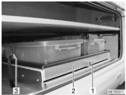
natural_image
Interior view of a vehicle showing a battery pack with labeled parts (1, 2, 3), no visible text or symbols beyond labels.Fig. 46 Sliding drawer
Opening: ■ Open the external flap as described above.
■ Pull the safeguard (Fig. 46,1) upwards.
■ Pull out the sliding drawer (Fig. 46,2).
■ Loosen the tension belts (Fig. 46,3).
7.3 Driver's cabin partition

▷ Only drive with the door secured.
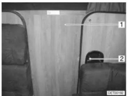
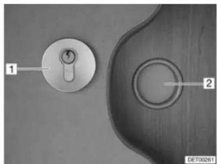
natural_image
Close-up of two metallic door lockers on a surface, labeled 1 and 2, with no visible text or symbols beyond labels.Fig. 47 Driver's cabin partition Fig. 48 Driver's cabin lock
Lock on the living area side
To close and open the driver's cabin partition:
Closing:
■ Release and close door (Fig. 47,1).
■ Turn the handle (Fig. 47,2) in an anticlockwise direction until the door is locked.
Opening:
■ Turn the handle (Fig. 47,2) in a clockwise direction until the door is unlocked.
■ Open the door (Fig. 47,1) and secure it.
Lock on the driver's cabin side
To close and open the driver's cabin partition:
Closing:
■ Release the door (Fig. 47,1) and close it with the handle (Fig. 48,2).
■ Insert the key into locking cylinder (Fig. 48,1) and turn in a clockwise direction until the door is locked.
Opening:
■ Insert key into locking cylinder and turn it in an anticlockwise direction.
■ Open the door and secure it.
7.4 Ventilation

The oxygen in the vehicle interior is used up by breathing and the use of gas operated appliances. That is why the oxygen needs to be replaced on a constant basis. For this purpose, forced ventilation options (e.g. skylights with forced ventilation, mushroom-shaped vents or floor vents) are fitted to the vehicle. Never cover or block forced ventilations from the inside or outside with objects such as e.g. a winter mat. Keep forced ventilations clear of snow and leaves. There is a danger of suffocation due to increased CO_2 levels.

Although sufficient ventilation is provided, in certain weather conditions, condensation can form on metal objects (e.g. screwed connections in the floor). Additional cold spots can occur at thermal "bridges" (e.g. mushroom-shaped vents, skylight edges, sockets, filler necks, flaps, etc.).
Condensation
Ensure that there is a continuous exchange of air by providing frequent and efficient ventilation. This is the only method for ensuring that condensation and resulting mould is not formed during cool weather. During the colder season, a pleasant living climate is created if heating output, air distribution and ventilation are synchronized. To avoid draft close the air outlet nozzles on the dashboard and set the air distribution of the base vehicle to air circulation.
If the vehicle is laid up for a longer period, occasionally ventilate it well, especially in summer as heat accumulation can occur. Do not only air the interior, but also the storage compartments which are accessible from the outside. Air the parking place as well if the vehicle is parked in a closed space (e.g. garage). The occurrence of condensation could lead to the formation of mould.
7.5 Windows

The windows are fitted with a blind or Roman shade and with an insect screen or folding insect screen. After the latch has been released, the blind and insect screen automatically spring back to the initial position by tensile force. In order not to damage the tension mechanics, hold onto the blind or insect screen and allow it to slowly return to the initial position. The Roman shade and folding insect screen are made of thin woven fabric. In order not to damage the Roman shade or the insect screen, grasp the respective handle and carefully return it to the initial position.
Do not keep blinds closed over a longer period of time as that can cause increased material wear.

If the blind or the Roman shade is completely closed, exposure to direct sunlight can cause heat to accumulate between the blind/the Roman shade and the glass window. The window could be damaged. For that reason, close the blind/Roman shade only 2/3 of the way in direct sunlight.
Before commencing the journey, close the windows.
▷ Depending on the weather, close the windows far enough to prevent moisture from entering.
To open and close the hinged window, open or close all catch levers which are fitted to the hinged window.

▷ When leaving the vehicle, always close the windows.
In extreme weather conditions or if the temperature fluctuates strongly, a light condensation film can form on the double-glazed acrylic glass. The glass is designed in such a way that condensation can evaporate when the external temperature increases. There is no danger of the double-glazed acrylic glass being damaged by condensation.
7.5.1 Hinged window with automatic hinges (with safety knob)

▷ Open the window completely, to release the lock. If the locking device is not released and the window is closed nevertheless, there is the danger of the window breaking due to the massive counter-pressure.
When opening the hinged windows, ensure that there are no torsional forces. Open and close the hinged windows evenly.
If the catch lever is equipped with a safety knob, press the safety knob when operating the catch lever.
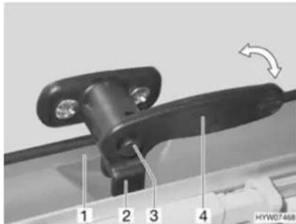
Fig. 49 Catch lever with safety knob in "closed" position
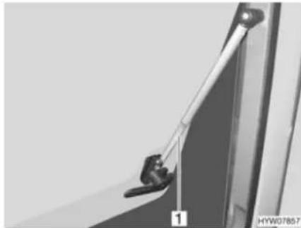
natural_image
Close-up of a mechanical hinge or latch mechanism with no visible text or symbolsFig. 50 Hinged window with automatic hinges
Opening:
■ Press the safety knob (Fig. 49,3) down and hold it.
■ Turn the catch lever (Fig. 49,4) a quarter turn towards the centre of the window.
■ Open the hinged window until the required locking position is reached; the automatic hinge (Fig. 50,1) automatically locks in place.
The hinged window remains locked in the required position.
Closing:
■ Open the hinged window as wide as necessary until the latch releases.
■ Close the hinged window.
■ Press the safety knob (Fig. 49,3) down and hold it.
■ Turn the catch lever (Fig. 49,4) a quarter turn towards the window frame. The fork (Fig. 49,2) on the catch lever is entirely on the inner side of the window catch (Fig. 49,1).
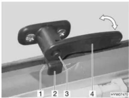
Fig. 51 Catch lever with safety knob in "continuous ventilation" position
Continuous ventilation
With the catch lever, the hinged window can be placed in two positions:
• "Continuous ventilation" (Fig. 51)
- Firmly closed (Fig. 49)
To place the hinged window into the "continuous ventilation" position:
■ Press the safety knob (Fig. 51,3) down and hold it.
■ Turn the catch lever (Fig. 51,4) a quarter turn towards the centre of the window.
■ Lightly open the hinged window outwards.
■ Press the safety knob (Fig. 51,3) down and hold it.
■ Return catch lever to its initial position. Move the fork (Fig. 51,2) on the catch lever into the window catch (Fig. 51,1).
■ Make certain that the safety knob is not pushed in but rather that it secures the catch lever.
During the journey, the hinged window may not be in "continuous ventilation" position.
If it rains, the "continuous ventilation" hinged window position could lead to splashing water penetrating the living area. Therefore, close the hinged windows completely.
7.5.2 Sliding window with lock
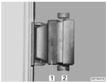
natural_image
Mechanical component with two labeled parts (1 and 2) mounted on a vertical frame, no visible text or symbols beyond labelsFig. 52 Sliding window with pressure lock
Opening:
■ Press the lock (Fig. 52,2) upwards.
■ Press handle (Fig. 52,1) and push it forward or backward at the same time.
■ Open window half up to the required position.
Closing: ■ Close the window as far as it can go.
■ Push the lock downwards.
7.5.3 Sliding window without lock
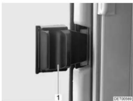
natural_image
Close-up of a black rectangular device mounted on a vertical pole, with a scale marker and 'DE T00589' label (no readable text or symbols beyond the label)Fig. 53 Sliding window without lock
Opening: ■ Press handle (Fig. 53,1) and push or pull it forward at the same time.
■ Open window half up to the required position.
Closing: ■ Close the window as far as possible and let the handle lock in place.
7.5.4 Gathered blinds
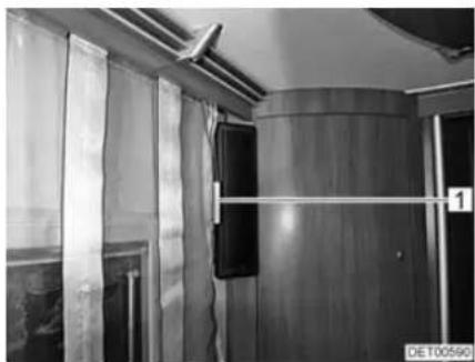
natural_image
Interior view of a train carriage with wooden doors, curtains, and ventilation ducts (no visible text or symbols)Fig. 54 Gathered blind Fig. 55 Cord weight
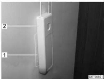
Depending on the model, the vehicle is fitted with gathered blinds.
Gathering the blind: ■ Pull down the cord weight (Fig. 54,1). The cords pull up and gather the blind.
■ Press the cord weight (Fig. 55,2) onto the Velcro (Fig. 55,1).
Lowering the blind: ■ Remove the the cord weight (Fig. 55,2) from the Velcro (Fig. 55,1).
■ Guide the cord weight slowly upwards. The bottom rod pulls the blind down.
7.5.5 Blind and insect screen

Depending on the window size, the blinds are fitted with one or two lock mechanisms.
Before commencing the journey, lock the insect screen into the blind and lock the blind into the first locking position. This helps to avoid vibration noises during the journey.
The windows are fitted with a blind and an insect screen. The blind and insect screen can be adjusted separately.
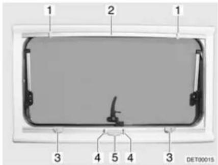
Fig. 56 Hinged window
Blind The blind is located in the bottom blind box.
Closing: ■ Press handle (Fig. 56,4) and draw blind (Fig. 56,5) from the bottom to the top up to the desired height.
■ Release handle. Blind locks into the nearest locking position.
Opening: ■ Clench handle (Fig. 56,4). Latch is released.
■ Slowly guide blind (Fig. 56,5) into its initial position.
Insect screen The insect screen is located in the upper blind box.
Closing: ■ Pull insect screen (Fig. 56,2) down until it touches the blind (Fig. 56,5). ■ Depending on the model, engage the closure latches (Fig. 56,1) or the one closure latch in the locks (Fig. 56,3) or the one lock.
Opening: ■ Depending on the model, release both locks (Fig. 56,3) or the one lock.
■ Slowly return insect screen into its initial position.
7.5.6 Roman shade and insect screen
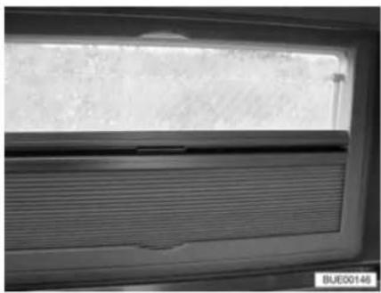
natural_image
Close-up of a window with horizontal slats and a textured surface, no visible text or symbolsFig. 57 Hinged window
Insect screen Depending on the frame fitting, the insect screen is fitted into the window frame at the top or bottom.
Closing:
■ Hold the bottom rod of the insect screen in the centre and pull it down carefully towards the bottom rod of the Roman shade.
■ Let the catch on the bottom rod of the insect screen snap into the Roman shade.
■ Continuous adjustment of the insect screen may be made by moving the bottom rods.
Opening:
■ Push the bottom rods towards the Roman shade.
■ Hold the bottom rod of the insect screen in the middle and activate the catch.
■ Carefully return the bottom rod of the insect screen to the limit stop on the frame.
Roman shade Depending on the frame fitting, the Roman shade is fitted into the window frame at the top or bottom.
Closing:
■ Hold the bottom rod of the Roman shade in the centre and pull it carefully towards the bottom rod of the insect screen.
■ Let the catch on the bottom rod of the Roman shade snap into the insect screen.
■ Continuous adjustment of the Roman shade may be made by moving the bottom rods.
Opening:
■ Push the bottom rods towards the insect screen.
■ Hold the bottom rod of the Roman shade in the centre and activate the catch on the bottom rod of the insect screen.
■ Carefully return the bottom rod of the Roman shade to the limit stop on the frame.
7.5.7 Blind for the windscreen
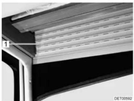
natural_image
Close-up of a mechanical component with layered structure and mounting bracket (no visible text or symbols)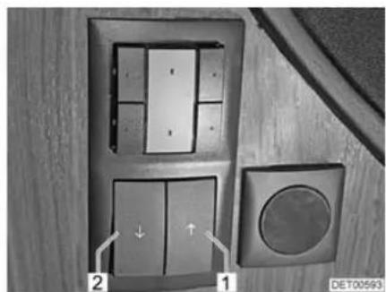
natural_image
Interior view of a door with two panels, one showing a circular button and arrow indicator (no text or symbols)Fig. 58 Blind, windscreen Fig. 59 Switch for blind, windscreen
The switch for operating the blind is installed in the panelling on the left next to the driver's seat.
Closing:
■ Press the left button (Fig. 59,2). The blind (Fig. 58,1) moves down.
Opening:
■ Press the right button (Fig. 59,1). The blind (Fig. 58,1) moves up.
7.5.8 Roman shades for driver's window and front passenger's window
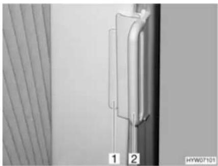
natural_image
Close-up of a vertical pipe or tube mounted on a wall, with two numbered labels (1 and 2) visible, against a plain background (no text or symbols beyond labels)Fig. 60 Roman shade, driver's cabin window
Closing:
■ Grasp the handle (Fig. 60,2) of the Roman shades and draw carefully until the magnetic catch keeps the Roman shades closed.
Opening:
■ Using the handle, carefully push back the Roman shades.
■ Push the handle (Fig. 60,2) onto the cap (Fig. 60,1). The Roman shade is secured.
7.6 Skylights
Depending on the model, skylights with or without forced ventilation are fitted to the vehicle. If a skylight is fitted without forced ventilation, the forced ventilation is performed using mushroom-shaped vents.

The apertures for forced ventilation must always be kept open. Never cover or block forced ventilations with objects such as e.g. a winter mat. Keep forced ventilations clear of snow and leaves.

The skylights are fitted with a blind or Roman shade and with an insect screen or folding insect screen. After the latch has been released, the blind and insect screen automatically spring back to the initial position by tensile force. In order not to damage the tension mechanics, hold onto the blind or insect screen and allow it to slowly return to the initial position. The Roman shade and folding insect screen are made of thin woven fabric. In order not to damage the Roman shade or the insect screen, grasp the respective handle and carefully return it to the initial position.
Do not keep blinds closed over a longer period of time as that can cause increased material wear.
If the blind or the Roman shade is completely closed, exposure to direct sunlight can cause heat to accumulate between the blind/the Roman shade and the skylight. The skylight could be damaged. For that reason, close the blind/Roman shade only 2/3 of the way in direct sunlight. Open the skylight slightly or move it to ventilation position.
▷ Depending on the weather, close the skylights far enough to prevent moisture from entering.
Do not climb on the skylights.
▷ Before commencing the journey, close the skylights.

Before commencing the journey, check that the skylights are closed and locked.
Before commencing the journey, open the blinds or Roman shades.
▶ Apply talc to the rubber seals of the skylights at least once a year.
▷ When leaving the vehicle, always close the skylights.

7.6.1 Skylight with snap latch
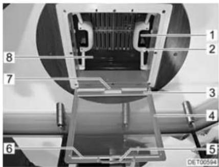
Fig. 61 Skylight with snap latch
The skylight can be pushed upwards either from one side or from both sides.
Opening:
■ Pull on the handle (Fig. 61,5).
■ Fold insect screen (Fig. 61,4) downward.
■ Push the spring-loaded latch (Fig. 61,1) towards the inside of the skylight (Fig. 61,8). At the same time use the handle (Fig. 61,2) to press the skylight upwards.
■ Swing insect screen upwards (Fig. 61,4) until it latches in place.
Closing:
■ Pull on the handle (Fig. 61,5).
■ Fold insect screen (Fig. 61,4) downward.
■ Using both handles (Fig. 61,2), pull down the skylight (Fig. 61,8) with force until the two snap latches (Fig. 61,1) lock into place.
■ Swing insect screen upwards (Fig. 61,4) until it latches in place.
Blind To close and open the blind:
Closing:
■ Pull the handle (Fig. 61,7) of the blind and hook the hook rail (Fig. 61,3) into the retainer (Fig. 61,6) on the insect screen.
Opening:
■ Release the hook rail (Fig. 61,3) from the retainer (Fig. 61,6) and feed the blind back slowly.
7.6.2 Hinged skylight
The hinged skylight may be opened on one side only. Three inclination angles and a ventilation position are available.
An extension hook is included as standard equipment.
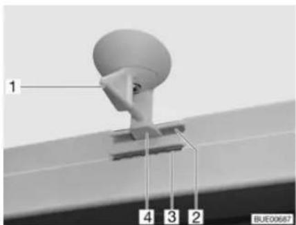
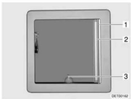
Fig. 62 Hinged skylight, lock Fig. 63 Hinged skylight
Opening:
■ Turn the lever (Fig. 62,1 or Fig. 63,3) one quarter turn.
■ Grip lever and push hinged skylight upwards.
Closing:
■ Grip lever and pull hinged skylight downwards.
■ Turn the lever one quarter turn. The latch (Fig. 62,4) must slide into the lower aperture (Fig. 62,3).
Locking in the ventilation position:
■ Grip lever and pull hinged skylight downwards.
■ Turn the lever one quarter turn. The latch (Fig. 62,4) must slide into the upper aperture (Fig. 62,2).

▷ If it rains and the hinged skylight is in ventilation position, that could lead to water penetrating the living area. Therefore close hinged skylight completely.
Roman shade The Roman shade may be closed at any position, either with the hinged sky-light open or closed.
Closing:
■ Pull out Roman shade (Fig. 63,1) and release in the required position. The Roman shade will stay in that position.
Opening:
■ Slowly push the Roman shade at the handle to its initial position.
Insect screen

The insect screen may be damaged if it is closed with the hinged skylight closed. Therefore only close the insect screen when the hinged skylight is open.
Closing:
■ Pull insect screen (Fig. 63,2) out until it engages with the latch on the opposite side.
Opening:
■ Slightly push up insect screen along the strip. The latch is released.
■ Slowly return insect screen into its initial position.
7.6.3 Heki skylight (mini and midi)
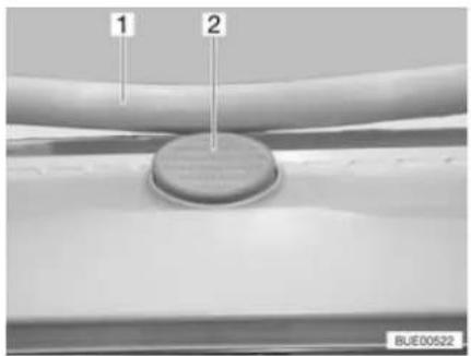
natural_image
Close-up of a mechanical component with two labeled parts (1 and 2), no readable text or symbols beyond labelsFig. 64 Safety knob on the Heki sky-light
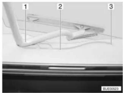
Fig. 65 Heki skylight, guide
The Heki skylight is opened on one side only.
Opening:
■ Press the safety knob (Fig. 64,2) and pull the bar (Fig. 64,1) down with both hands.
■ Pull the bar (Fig. 65,1) in the guides (Fig. 65,2) to the rearmost position (Fig. 65,3).
Closing:
■ Use both hands to push the bar (Fig. 65,1) slightly upwards.
■ Push the bar back in the guides.
■ Push the bar upwards with both hands until it is above the safety knob (Fig. 64,2).
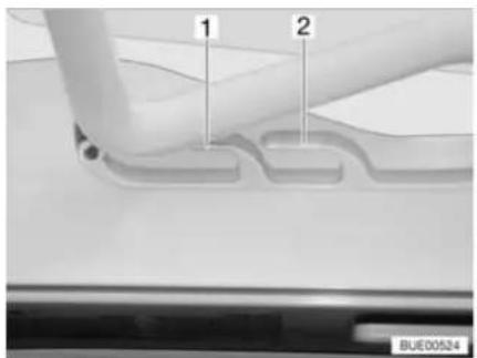
Fig. 66 Heki skylight in ventilation position
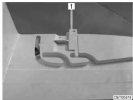
natural_image
Close-up of a mechanical component with a 3D outline and a vertical rod, no visible text or symbolsFig. 67 Ventilation position locking mechanism
Ventilation position
The Heki skylight can be put in two ventilation positions: Bad weather position (Fig. 66,1) and central position (Fig. 66,2). Depending on the model, the skylight can be locked in the central position with the latch (Fig. 67,1).
■ Press the safety knob (Fig. 64,2) and pull the bar (Fig. 64,1) down with both hands.
■ Pull the bar in the guides (Fig. 65,2) to the desired position.
■ Push the bar slightly upwards and into the selected guide (Fig. 66,1 or 2) and lock if necessary.
Roman shade To close and open the Roman shade:
Closing:
■ Pull out Roman shade at the handle and release in the required position. The Roman shade will stay in that position.
Opening: ■ Slowly push the Roman shade at the handle to its initial position.
Insect screen To close and open the insect screen:
Closing: ■ Pull the insect screen by the handle to the opposite handle of the Roman shade.
Opening: ■ Press the rear part of the handle of the insect screen. The latch is released.
■ Use handle to return the insect screen slowly to its initial position.
7.6.4 Wind-up skylight
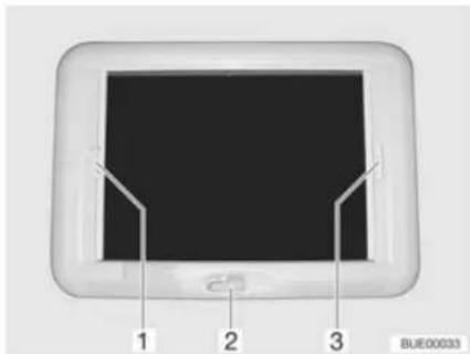
Fig. 68 Wind-up skylight
The wind-up skylight can be opened using the manual crank.
Opening: ■ Rotate the hand crank (Fig. 68,2) until a resistance can be felt (max. opening angle 70°).
Closing: ■ Rotate the hand crank until the wind-up skylight is closed. The wind-up skylight can be locked after rotating two or three more times.
- Check the locking mechanism. To do so, press your hand against the acrylic glass.
Roman shade The Roman shade can be closed in any position, as desired. If the Roman shade is locked with the insect screen, the insect screen is also moved along on closing the Roman shade.
Closing: ■ Pull the handle of the Roman shade (Fig. 68,3) and release in the desired position. The Roman shade will stay in that position.
Opening: ■ Slowly push the Roman shade at the handle to its initial position.
Insect screen If the insect screen is locked with the Roman shade, the Roman shade is also moved along on closing the insect screen.
Closing: ■ Pull insect screen at the handle (Fig. 68,1) to the opposite handle of the Roman shade (Fig. 68,3) and allow to engage.
Opening: ■ Press the handle of the insect screen (Fig. 68,1) at the back upwards and detach the insect screen from the Roman shade (Fig. 68,3).
■ Slowly push insect screen at the handle to its initial position.
7.7 Rotating seats

Before commencing the journey, rotate all swivel seats in the direction of travel and lock in position. During the journey, the swivel seats must remain locked in place in the direction of travel.

Setting the position of the seats and armrests is described in chapter 5.
The lever for rotating the seat is located on the front of the seat.
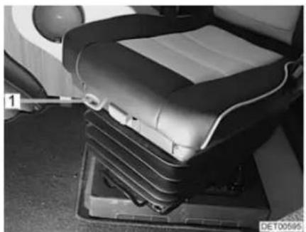
natural_image
Interior view of a car seat with visible seats and a tool inserted, no text or symbols present.Fig. 69 Driver's and front passenger's seats (SKA)
Turning:
■ Push both armrests at the driver's/front passenger's seat upward.
■ Push the driver's seat/front passenger's seat backwards or into the central position.
■ Pull the lever (Fig. 69,1) to turn the seat. The seat is released from the locking device.
The seats can be rotated in any direction. The seats can only be locked in position in the direction of travel.
7.8 Tables
7.8.1 Suspension table with folding table-top extension
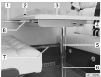
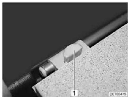
natural_image
Close-up of a mechanical component with a knob and textured surface, labeled '1' (no readable text or symbols beyond label)Fig. 70 Extend suspension table Fig. 71 Suspension table with fold-out leg
The table surface of the suspension table size can be enlarged by folding out a table element.
Extending:
■ Release the locking lever (Fig. 70,4) underneath the table-top.
■ Slightly lift the front of the table-top (Fig. 70,3) and pull it to the middle of the vehicle as far as it will go.
■ The inserted table-top extension (Fig. 70,8) pivots upwards.
■ Push the table-tops together until the catch audibly locks into place.
Reducing size:
■ Release the locking lever (Fig. 70,4) underneath the table-top.
■ Slightly lift the front of the table-top and pull it out completely.
■ Push back the table-top. The table-top extension pivots downwards.
■ Lift up the front of the table-top slightly and push it all the way in.
The suspension table may also be used as a bed foundation.
Conversion to bed foundation:
■ Lift the front of the table-top by approx. 45°.
■ Pull out the lower part of the support leg (Fig. 70,6) down and lay aside.
■ Press the release knob (Fig. 71,1) on the lock (Fig. 70,2)
■ Detach the suspension table from the upper attachment rail (Fig. 70,1).
■ Hook the suspension table into the lower attachment rail (Fig. 70,7) and set it down onto the floor with the upper part of the support leg (Fig. 70,5).
7.8.2 Fixed table (movable table-top)
The top of the fixed table can be moved both lengthways and crossways.
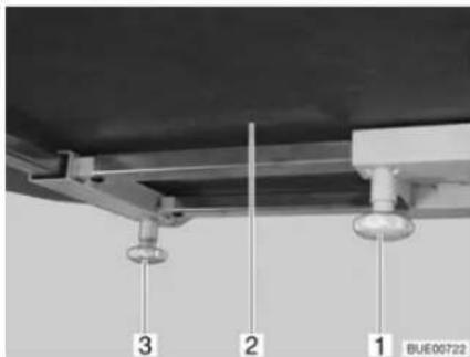
Fig. 72 Fixed table
Moving in a lengthways direction:
■ Loosen knurled screw (Fig. 72,1).
■ Move table-top (Fig. 72,2) to the desired position.
■ Retighten the knurled screw.
Moving in a crossways direction:
■ Loosen knurled screw (Fig. 72,3).
■ Move table-top (Fig. 72,2) to the desired position.
■ Retighten the knurled screw.
The fixed table cannot be used as a bed foundation.
7.9 Central locking system for kitchen unit
Depending on the model, the kitchen unit is fitted with a central locking system. When you start the vehicle engine, the central locking system is activated automatically.
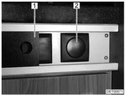
natural_image
Close-up of a mechanical component with labeled parts (1 and 2), no readable text or symbols beyond labelsFig. 73 Switch for the kitchen unit's central locking system
1 Panel
2 Switch for the kitchen unit's central locking system
Unlocking:
■ Push the panel (Fig. 73,1) to the side.
■ Press the upper part of the switch (Fig. 73,2). The flaps and drawers of the kitchen unit are unlocked.
■ Push the panel (Fig. 73,1) to the side.
■ Press the lower part of the switch (Fig. 73,2). The flaps and drawers of the kitchen unit are locked.
Locking manually:
7.10 Television

Before commencing the journey, remove the television from the support and store it securely.
Before commencing the journey, place and secure the flat screen and screen support in the initial position. If the screen holder is installed in a TV cabinet: Close TV cabinet.
Before commencing the journey, ensure that the antenna is in park position. Danger of accidents!
Flat screen in the TV cabinet
The flat screen is attached to a console in the TV cabinet.
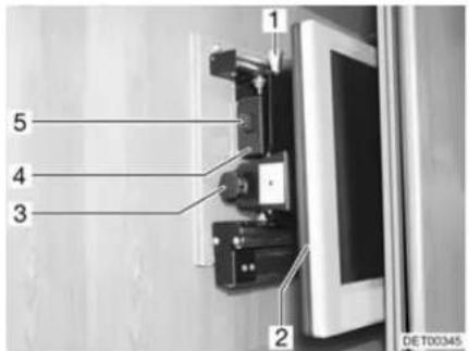
Fig. 74 TV cabinet
Pulling the television console forward:
Swivelling the television console:
■ Press the release knob (Fig. 74,5) and pull the holder for the flat screen forward as far as possible by the handle (Fig. 74,4).
■ Pull the release knob (Fig. 74,1) and swivel flat screen (Fig. 74,2) to the desired position.
■ Loosen knurled screw (Fig. 74,3).
■ Set the desired angle for the flat screen and re-tighten the knurled screw.
Flat screen with jointed arm
The flat screen is fastened to a jointed arm.
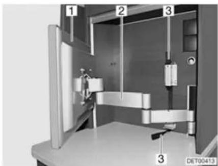
natural_image
3D mechanical assembly diagram showing internal components and labeled parts (no readable text or symbols)Fig. 75 Flat screen with jointed arm
Positioning the flat screen with jointed arm:
■ Pull on the fabric strip (Fig. 75,3) to unlock the jointed arm (Fig. 75,2).
■ Swivel flat screen (Fig. 75,1) into the required position.
■ Take hold of the flat screen at the top and bottom edge with both hands and set the desired angle of inclination.
7.11 Lamps

▶ Bulbs and light fittings can be extremely hot.
▶ Allow the light bulbs and lamp holders to cool down before touching them.
If the light is switched on or still hot, there must always be a safety distance of at least 30 cm between stores or curtains and flammable objects. Fire hazard!
Spotlight The spotlight can be both swivelled and pushed.
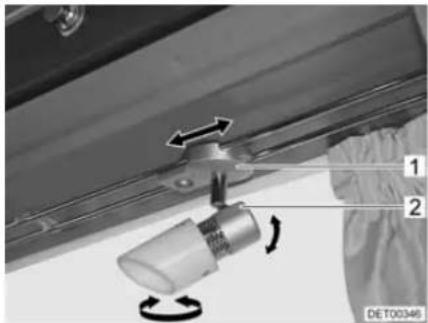
natural_image
Mechanical assembly diagram showing a rotating component with directional arrows, no text or symbols presentFig. 76 Spotlight
Swivelling the spotlight:
■ Grasp the housing (Fig. 76,2) and swivel it.
The spotlight can be swivelled in various directions:
• To the left and to the right
- Up and down
Shifting spotlight:
■ Grasp the holder (Fig. 76,1).
■ Push spotlight along the rail system to desired position.
Plug-in light
The plug-in lights can be plugged into the sockets provided. The sockets are distributed throughout the vehicle.
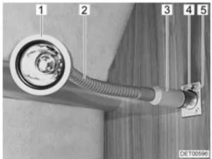
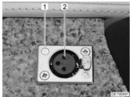
natural_image
Close-up of a wall-mounted electrical socket with two labeled points (1 and 2), no visible text or symbols on the socket itself.Fig. 77 Socket with plugged-in light Fig. 78 Socket
Removing a plug-in light:
■ Grip the plug-in light at the base (Fig. 77,3).
■ Push the release knob (Fig. 77,4).
■ Pull the plug-in light (Fig. 77,1) out of the socket (Fig. 77,5).
■ Insert the plug in the base of the plug-in light into the socket (Fig. 78,1) until it engages audibly. When doing this, pay attention to the position of the contacts (Fig. 78,2).
Plugging in the plug-in light:
Grip the plug-in light by the "swan neck" (Fig. 77,2) (if present) or by the housing, and swivel.
Swivelling the plug-in light:
7.12 Light switch

The light switches have different layouts according to the model. The light switches are located either directly on the corresponding lamp or next to the lamp, e.g. in the vicinity of the seating group.
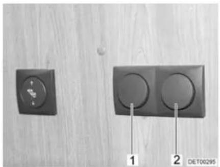
natural_image
Two black electrical switches on a wooden surface, one with a circular button and the other with two circular buttons, labeled 1 and 2 (no text or symbols on the switches themselves)Fig. 79 Light switch, entrance area
The bottom of the entrance area has light switches for the following lamps:
- Awning light (Fig. 79,1)
- Seating group lighting (Fig. 79,2)
7.13 Light control
Functions
Depending on the model, the vehicle is fitted with a central lighting system. This lighting system operates and dims single lamps or lamp groups.
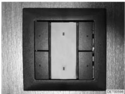
natural_image
Close-up of a rectangular electronic component with internal compartments and mounting holes (no visible text or symbols)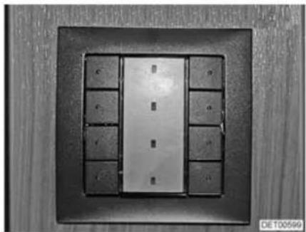
natural_image
Close-up of a metallic panel with multiple small rectangular cutouts, mounted on a dark square frame (no visible text or symbols)Fig. 80 Light switch with four buttons Fig. 81 Light switch with eight buttons
Switch The lights are operated via switches which are installed at different places in the vehicle. The switches each have two, four (Fig. 80) or eight (Fig. 81) buttons. Not all functions are available on each switch. The functions of the individual switches and buttons are programmed individually, depending on the configuration. A function is switched on and off via the same button.
7.14 Remote control for awning light, canopy light and entrance step
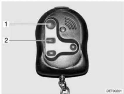
Fig. 82 Remote control
The remote control has the following functions:
- Switching the awning light on and off (Fig. 82,1)
- Switching the canopy light on and off (Fig. 82,2)
• Extending the entrance step - Retracting the entrance step
7.15 Extending the seating group
7.15.1 Extending the central seating group
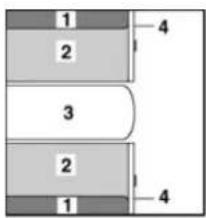
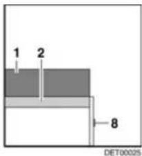
Fig. 83 Before extending
1 Back cushion
2 Seat cushion
3 Table
4 F I a p
5 Additional cushion
6 Additional cushion
7 Bench seat extension
8 Handle
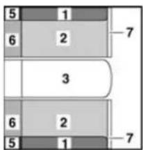
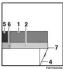
Fig. 84 After extending
■ Extend the table (Fig. 83,3) (see section 7.8).
■ Pull on the handle (Fig. 83,8) and open the flap (Fig. 83,4).
■ Fold up bench seat extension (Fig. 84,7) and wedge together with the flap (Fig. 84,4).
■ Place the back cushions (Fig. 84,1) and the seat cushions (Fig. 84,2) on the bench seat extension.
■ Insert the additional cushions (Fig. 84,6) between the seat cushions and the exterior wall.
■ Insert the additional cushions (Fig. 84,5) between the back cushions and the exterior wall.
7.15.2 Extending the central seating group with divan
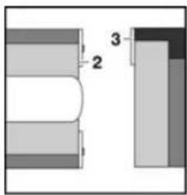
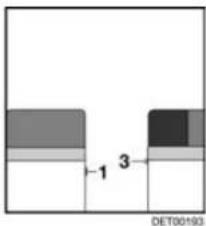
1 Handle
2 F I a p
3 Slatted frame
4 Bench seat extension
5 Additional cushion
6 Additional cushion
Fig. 85 Prior to conversion
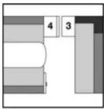
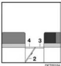
Fig. 86 During conversion
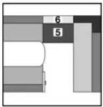
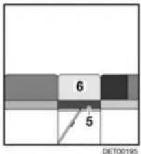
Fig. 87 After conversion
■ Close driver's cabin partition (see section 7.3).
■ Pull on the handle (Fig. 85,1) and open the flap (Fig. 85,2).
■ Fold up bench seat extension (Fig. 86,4) and wedge together with the flap (Fig. 86,2).
■ Unlock and pull out the slatted frame (Fig. 86,3).
■ Place the additional cushion (Fig. 87,5) on the slatted frame and the bench seat extension.
■ Place the additional cushion (Fig. 87,6) on the additional cushion (Fig. 87,5).
7.16 Beds
7.16.1 Overcab bed

The maximum permitted overcab bed load is 200 kg.
▶ Only use the overcab bed, if the safety net is set up.
▶ Never allow small children to remain in the overcab bed without supervision.
▶ But in particular with regard to small children less than 6 years of age, users should ensure that they cannot fall out of the overcab bed.
▶ Use separate children's beds or travel cots suitable for children.

Do not load the overcab bed without mattress. The plastic mould part can break!
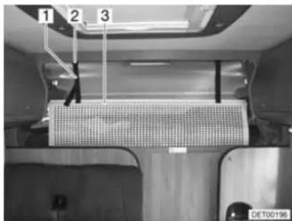
Fig. 88 Overcab bed
Access ladder Always use the access ladder provided as standard to access the overcab bed.
Safety net
The safety net (Fig. 88,3) is stored as standard between the mattress and slatted frame. Only use the safety net if persons are already in the alcove.
Setting up:
■ Fasten the retaining straps (Fig. 88,1) to the holders on the ceiling (Fig. 88,2).
Folding mechanism
The overcab bed can be folded up. This simplifies passage from driver's cabin to living area.
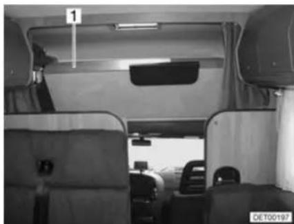
natural_image
Interior view of a vehicle cabin with seats and overhead equipment (no visible text or symbols)Fig. 89 Overcab bed, folded upwards
Folding upwards:
■ Open driver's cabin partition (see section 7.3).
■ Lift the mattress forwards and set it down on the panel.
■ Fold the front of the overcab bed (Fig. 89,1) upwards. The overcab bed is kept in the upper position by gas-pressure springs.
Folding downwards:
■ Pull overcab bed downwards.
■ If necessary, push the mattress behind the panel.
7.16.2 Pull-down bed, electronically lowerable

The maximum permitted pull-down bed load is 200 kg.
The pull-down bed is not to be used for the storage of luggage.
▶ Only use the pull-down bed, if the safety net is set up.

▶ Never allow small children to remain in the pull-down bed without supervision.
▶ But in particular with regard to small children less than 6 years of age, users should ensure that they cannot fall out of the pull-down bed.
▶ Use separate children's beds or travel cots suitable for children.
▶ Switch off the reading lamps in the pull-down bed before the bed is pushed up. Fire hazard!
▶ Depending on the seat model, the backrest is under strong spring tension. If there is no resistance to the backrest in these seats, it quickly moves forward after unlocking.
▶ Do not reach into the area between the bed and the side wall when lowering or raising. Danger of bruises!
▶ Only lower or raise the bed when the space between the bed and the side wall is clear.
▶ Only lower the bed if the area under the bed is clear.
Preparing the driver's cabin
The rests of the driver's and front passenger's seats must be tipped forwards before the pull-down bed is lowered.
■ Turn the driver's and the front passenger's seat to the direction of travel, lock it in place and move them backwards.
■ Tip the backrest forwards.
■ Close the shade in the driver's cabin.
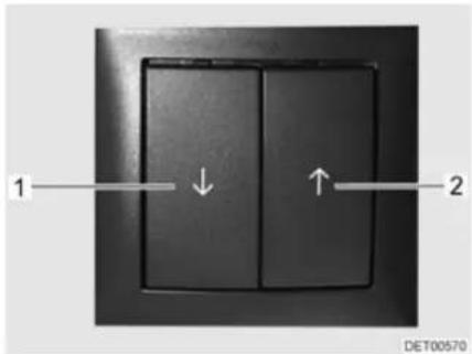
Fig. 90 Switch for pull-down bed
Lowering the pull-down bed:
■ Press the rocker switch (Fig. 90,1) above the divan, and keep it pressed until the bed is completely lowered.
■ Switch off the reading lamps in the pull-down bed.
■ Press the rocker switch (Fig. 90,2) above the divan, and keep it pressed until the bed is completely raised.
Moving the pull-down bed upwards:
Access ladder
Always use the access ladder provided as standard to access the pull-down bed.
Safety net
The safety net is stored as standard between the mattress and slatted frame. Only use the safety net if persons are already in the pull-down bed.
7.16.3 Fixed bed (gas-pressure springs)
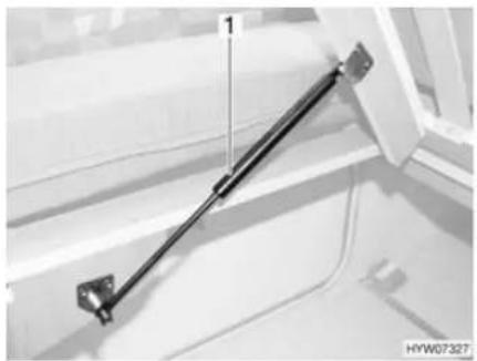
natural_image
Close-up of a mechanical suspension rod mounted on a vehicle door frame (no visible text or symbols)Fig. 91 Fixed bed
A storage compartment is underneath the bed. Lift up the slatted frame to place items in the storage compartment or to empty it from the inside of the vehicle.
Opening:
■ Lift the mattress forwards and set it down on the panel.
■ Lift slatted frame. The gas-pressure springs (Fig. 91,1) hold the slatted frame open.
Closing:
■ Press the slatted frame downwards against the resistance of the gas-pressure springs.
■ If necessary, push the mattress behind the panel.
7.17 Converting seating groups for sleeping
7.17.1 Central seating group
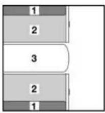
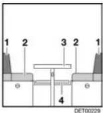
1 Back cushion
2 Seat cushion
3 T a b l e
4 Mounting rail
5 Additional cushion
Fig. 92 Prior to conversion
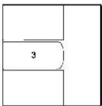
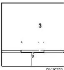
Fig. 93 During conversion

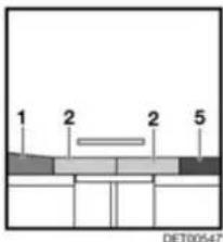
Fig. 94 After conversion
■ Convert the table (Fig. 92,3) to a bed foundation (see section 7.8).
■ Pull the seat cushions (Fig. 94,2) into the centre.
■ Place the back cushion (Fig. 94,1) between the seat cushion and the wall.
■ Insert the additional cushion (Fig. 94,5) between the seat cushion and the wall.
7.17.2 Central seating group with extension
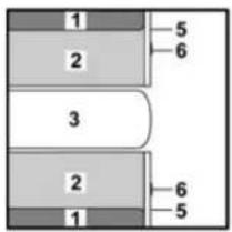
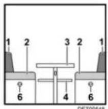
Fig. 95 Prior to conversion
1 Back cushion
2 Seat cushion
3 T a b l e
4 Mounting rail
5 F I a p
6 Handle
7 Bench seat extension
8 Additional cushion
9 Additional cushion
10 Additional cushion
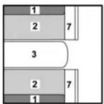
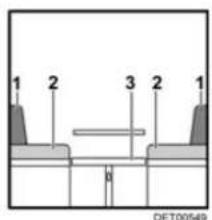
Fig. 96 During conversion
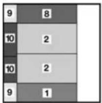
bar_stacked
| Category | Value 1 | Value 2 | |---|---|---| | Row 1 | 9 | 8 | | Row 2 | 10 | 2 | | Row 3 | 10 | 2 | | Row 4 | 9 | 1 |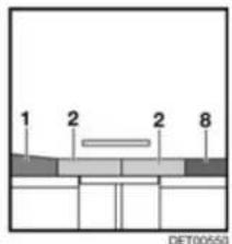
Fig. 97 After conversion
■ Convert the table (Fig. 95,3) to a bed foundation (see section 7.8).
■ Pull on the handle (Fig. 95,6) and open the flap (Fig. 95,5).
■ Fold up the bench seat extension (Fig. 96,7) and wedge it with the flap.
■ Pull the seat cushions (Fig. 97,2) forwards onto the table.
■ Place the back cushion (Fig. 97,1) between the seat cushion and the wall.
■ Insert the additional cushion (Fig. 97,8) between the seat cushion and the wall.
■ Insert the additional cushions (Fig. 97,9) between the cushions and the wall.
■ Insert the additional cushions (Fig. 97,10) between the cushions and the wall.
7.17.3 Central seating group with divan
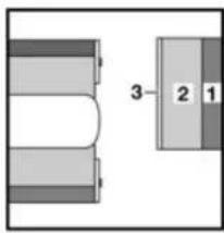
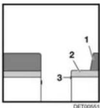
1 Back cushion
2 Seat cushion
3 Slatted frame
4 Additional cushion
Fig. 98 Prior to conversion
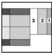
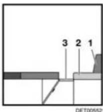
Fig. 99 During conversion
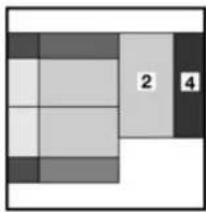
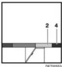
Fig. 100 After conversion
■ Extend the table and convert it into a bed foundation (see section 7.8).
■ Convert the central seating group for sleeping (see section 7.17.2).
■ Remove the back cushion (Fig. 99,1) and lay it aside.
■ Pull out the slatted frame (Fig. 99,3).
■ Pull the seat cushion (Fig. 100,2) to the central seating group.
■ Insert the additional cushion (Fig. 100,4) between the seat cushion and the exterior wall.
Chapter overview
This chapter contains instructions regarding the gas system of the vehicle.
The instructions address the following topics:
- safety
- gas consumption
- changing the gas bottles
- gas isolator taps
- hose break guard
• external gas connection
• automatic switching facility
The operation of the gas operation appliances of the vehicle is described in chapter 10.
8.1 General

Before commencing the journey, when leaving the vehicle or when gas equipment is not in use, close all gas isolator taps and the main isolator tap on the gas bottle.
▶ No appliance operated by a naked flame (e.g. heater or refrigerator) may be in operation when filling the tank, on ferries or in the garage. Danger of explosion!
▶ Do not use appliances operated with a naked flame in closed spaces (e.g. garages). Danger of poisoning and suffocation!
▶ Only have the gas system maintained, repaired or altered by an authorised specialist workshop.
▶ Have the gas system checked by an authorised specialist workshop according to the national regulations before commissioning. This also applies for not registered vehicles. For modifications to the gas system have the gas system immediately checked by an authorised specialist workshop.
The gas pressure regulator and exhaust gas pipes must also be inspected. The gas pressure regulator has to be replaced after 10 years at the latest. The vehicle owner is responsible for seeing that this is carried out.
In case of a defect of the gas system (gas odour, high gas consumption) there is danger of explosion! Close regulator tap on the gas bottle immediately. Open doors and windows and ventilate well.
If the gas system is defective: Do not smoke; do not ignite any open flames, and do not operate electric switches (light switches etc.).
▶ Before using the cooker make sure that there is sufficient ventilation. Open windows or the skylight.
▶ Do not use the gas cooker or gas oven for heating purposes.
If there are several gas devices, each gas device must have its own gas isolator tap. If individual gas devices are not in use, close the respective gas isolator tap.
▶ Ignition safety valves must close within 1 minute after the gas flame has extinguished. A clicking sound is audible. Check function from time to time.

The built-in gas devices are exclusively meant for use with propane or butane gas or a mixture of both. The gas pressure regulator as well as all built-in gas devices are designed for a gas pressure of 30 mbar.
▶ Propane gas is capable of gasification up to -42^ , whereas butane gas gasifies at 0^ . Below these temperatures no gas pressure is available. Butane gas is unsuitable for use in winter.
▶ Regularly inspect the gas tube fitted to the gas bottle connection for tightness. The gas tube must not have any tears and must not be porous. Have the gas tube replaced by an authorised specialist workshop no later than ten years after the manufacturing date. The operator of the gas system must see to it that the parts are replaced.
▶ Due to its function and construction, the gas bottle compartment is a space which is open to the exterior. Never cover or block up the standard forced ventilations. Otherwise gas that is emitted can not be diverted to the outside.
▶ Do not use the gas bottle compartment as storage space as it is not moisture-proof.
- Secure the gas bottle compartment against unauthorised access. To do this, lock the compartment.
The regulator tap on the gas bottle must be accessible.
▶ Only connect gas-operated devices (e.g. gas grill) which have been designed for a gas pressure of 30 mbar.
The exhaust gas pipe must be fitted tightly to the heating system and to the vent and must be sealed. The exhaust gas pipe must not show any evidence of damage.
Exhaust fumes must be able to escape into the atmosphere unhindered and fresh air must be able to enter unhindered. For this reason, keep the exhaust pipe and intake openings clean and unobstructed (e.g. free from snow and ice). For this reason, no snow walls or aprons may lie against the vehicle.
8.2 Gas bottles

Gas bottles are only to be transported within the designated gas bottle compartment.
Place the gas bottles in vertical position in the gas bottle compartment.
▶ Fasten the gas bottles so that they are unable to turn or tilt.
▶ If the gas bottles are not connected to the gas tube, always place the protective cap on top.
▶ Close the regulator tap on the gas bottle before the gas pressure regulator or gas tube are removed from the gas bottle.
The gas pressure regulator or the gas tube must only be secured with a suitable gas spanner (Do not overtighten).
▶ Only use special gas pressure regulators with a safety valve designed for vehicle use. Other gas pressure regulators are not permitted and cannot meet the demanding requirements.
▶ Use the gas pressure regulator defroster if the temperature falls below 5^ C.

▶ Use only 11 kg or 5 kg gas bottles. Camping gas bottles with built-in check valve (blue bottle with max. 2.5 or 3 kg content) are can be used in exceptional cases with a safety valve.
▶ Use the shortest possible tube lengths (150 cm max.) for external gas bottles.
▶ Never block the floor ventilation openings below the gas bottles.

For gas-operated units the gas pressure must be reduced to 30 mbar.
▷ Connect gas pressure regulator complete with safety valve directly to bottle valve.
The gas pressure regulator reduces the gas pressure in the gas bottle down to the operating pressure of the gas devices.
For filling and connecting the gas bottles in Europe the accessories shops have corresponding Euro filling sets and Euro bottle sets.
▷ Information available at the dealers or service centre.
For information on the gas supply in Europe see chapter 17.
8.3 Gas consumption

The data about gas consumption of the individual gas devices is standard average values.
| Appliances Gas consumption in grams/hour | |
| Cooker, per cooker Approx. 140 - 165 g/hRefrigerator Approx. 18 g/h | |
8.4 Changing gas bottles

When changing gas bottles, do not smoke or create any open fire.
When you have changed the gas bottle, check whether gas escapes at the connection points and unions. Use a leakage search spray to spray the relevant connection point or union. These agents are available at the accessories shop.
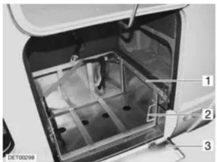
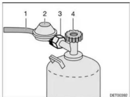
Fig. 101 Gas bottle compartment Fig. 102 Gas bottle connection
■ Open external gas bottle compartment (see section 7.2).
■ Fold guard plate (Fig. 101,3) down.
■ Set handle (Fig. 101,2) into a horizontal position.
■ Pull out the slide (Fig. 101,1) as far as possible.
■ Close the regulator tap (Fig. 102,4) on the gas bottle. Pay attention to the direction of the arrow.
■ Unscrew the gas pressure regulator (Fig. 102,2) from the gas bottle at the hexagon nut (Fig. 102,3).
■ Remove the gas pressure regulator and the gas tube (Fig. 102,1) from the gas bottle.
■ Release the fixing belts and remove the gas bottle.
■ Place a filled gas bottle in the gas bottle compartment.
■ Fix gas bottle in place with the fixing belts.
■ Position the gas pressure regulator (Fig. 102,2) and the gas tube (Fig. 102,1) on the gas bottle and screw in tightly to the gas bottle at the hexagonal nut (Fig. 102,3).
■ Push in the slide (Fig. 101,1) as far as possible, and set the handle (Fig. 101,2) in a vertical position.
■ Fold guard plate (Fig. 101,3) up.
■ Close the external flap (see section 7.2).
8.5 Gas isolator taps
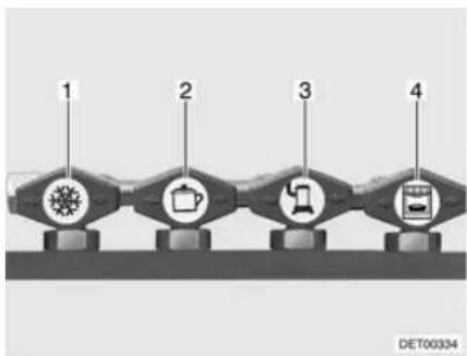
flowchart
graph LR
    A["1"] --> B["2"]
    B --> C["3"]
    C --> D["4"]
1 Refrigerator
2 Cooker
3 Heater/boiler
4 O v e n
Fig. 103 Symbols for the gas isolator taps
A gas isolator tap (Fig. 103) for every gas device is built into the vehicle.
The gas isolator taps are located under the cooker or in the vicinity of the gas devices (e.g. in the bench seat).
8.6 Hose break guard (crash protection unit)

When the vehicle is equipped with the crash protection unit the living area heater may be operated during the journey.
Also read the manufacturer's instruction manual.
The crash protection unit protects against unwanted gas discharge. In the event of an accident or a too high angle of the vehicle the gas supply will automatically be interrupted.
Construction of the unit
The crash protection unit consists of a control unit, an electrical valve and the operating unit with a tricoloured LED.
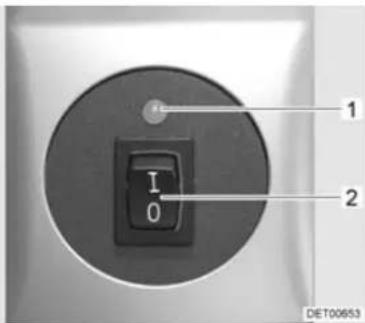
Fig. 104 Operating unit
Only the electrical functions can be switched at the operating unit (Fig. 104). The regulator taps on the gas bottles must be opened manually.
The indicator lamp on the operating unit shows the condition of the gas system. The system is okay when the indicator lamp (Fig. 104,1) lights up green. When the indicator lamp lights up or flashes red a fault has occurred. The gas supply is interrupted.
Putting into operation:
■ Open regulator taps on the gas bottles.
■ Switch on the system at the operating unit (Fig. 104). For this, set the rocker switch (Fig. 104,2) to "I". The indicator lamp (Fig. 104,1) flashes yellow (system test) and lights up green.
Switching off:
■ Set the rocker switch (Fig. 104,2) to "O". The indicator lamp (Fig. 104,1) goes out.
■ Close regulator taps on the gas bottles.
8.7 External gas connection

▶ If the external gas connection is not in use, always close the gas isolator tap.
▶ Only gas appliances with a suitable adapter should be connected to the external gas connection.
▶ Connect only external gas appliances which are designed for an operation pressure of 30 mbar.
Once you have made the connection and opened the gas isolator tap, make sure that no gas is escaping at the connection point. If there is a leak in the external gas connection, gas will escape into the open air. Immediately close the gas isolator tap and the regulator tap on the gas bottle. Have the external gas connection checked by an authorised specialist workshop.
When connecting an external gas appliance, make sure that there is nothing near the external gas connection that could cause a spark.
▶ Do not use the external gas connection to fill gas bottles. Observe the information stickers on the external gas connection.
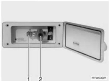
natural_image
Interior view of an electronic device showing internal components and a lid (no visible text or symbols)Fig. 105 External gas connection, gas isolator tap closed
The external gas connection (Fig. 105) is located at the rear or to the left or right of the vehicle depending on the model.
■ Connect the external gas device to the connection point (Fig. 105,1).
■ Open the gas isolator tap (Fig. 105,2).
8.8 Duomatic switching facility

▶ Do not use the switching facility in closed spaces.

If the vehicle is equipped with a panel of the DT series and the switching facility is operated via this panel, the operating unit is redundant.
▶ Further information can be obtained in the device manufacturer's instruction manual.
The Duomatic is an automatic switching facility with a remote display for a two-bottle gas system. The Duomatic switching facility automatically switches gas supply from the primary bottle to the reserve bottle as soon as the primary bottle is either empty or no longer ready for operation. The gas appliances may still continue operation. The Duomatic switching facility is suitable for all commercial gas bottles from 3 kg to 33 kg.
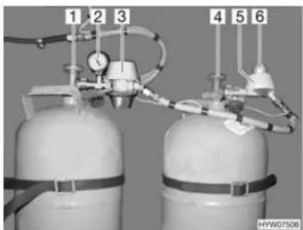
natural_image
Two gas cylinders with attached tubing and pressure gauges, no visible text or symbols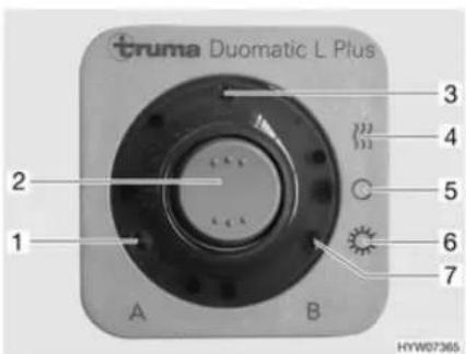
Fig. 106 Duomatic switching facility Fig. 107 Operating unit
Construction of the unit
The Duomatic switching facility consists of a central regulator (Fig. 106,3) and a switching regulator (Fig. 106,5). The knob (Fig. 106,6) on the switching regulator is used to select which of the gas bottles is to be used as a primary bottle and which is to be used as a reserve bottle.
Both regulators are equipped with a pressure controller and the regulator defroster Eis-Ex. This prevents damage to the gas system during the winter months.
The pressure gauge (Fig. 106,2) on the central regulator indicates the pressure in the gas bottle, not the filling level of the gas bottle. The pressure gauge can be used to test the impermeability of the gas bottle.
Only the electrical functions can be switched at the operating unit (Fig. 107). The regulator taps on the gas bottles (Fig. 106,1 and 4) must be opened manually.
The central regulator provides a constant gas pressure, regardless of which gas bottle is being drawn upon. The two indicator lamps on the operating unit show which gas bottle can be used to provide gas. When both indicator lamps are illuminated, the position of the knob on the switching regulator indicates which gas bottle is currently being drawn upon.

When operating with only one gas bottle (e.g. during the summer) connect the central regulator to this bottle. Position the knob on the switching regulator in the red area.
Operating modes The Duomatic switching facility has two operating modes:
● Winter operation "On and heating"
- Summer operation "On"
Putting into operation:
■ Open the regulator taps on the gas bottles (Fig. 106,1 and 4).
■ Use the knob (Fig. 106,6) on the switching regulator (Fig. 106,5) to select the gas bottle which is to be the primary source of gas (primary bottle). Always turn the knob as far as it will go.
When the knob is in the red area, the gas is taken primarily from the gas bottle with the central regulator (Fig. 106,3).
When the knob is in the green area, the gas is taken primarily from the gas bottle with the switching regulator (Fig. 106,5).
■ Switch on the Duomatic switching facility at the operating unit (Fig. 107). To do so, set the rocker switch (Fig. 107,2) to winter operation "On and heating" (Fig. 107,4) or to summer operation "On" (Fig. 107,6). Both gas pressure regulators are now ventilated. The operating indicator (Fig. 107,3) lights up.
Switching off:
■ Set the rocker switch (Fig. 107,2) to "O" (Fig. 107,5). The operating indicator (Fig. 107,3) goes out.
■ Close the regulator taps on the gas bottles (Fig. 106,1 and 4).
Remote display
The indicator lamps on the operating unit (Fig. 107) indicate in the vehicle interior whether the gas bottles are ready for operation.
- Indicator lamp "A" (Fig. 107,1): Gas bottle on the central regulator
- Indicator lamp "B" (Fig. 107,7): Gas bottle on the switching regulator
Changing gas bottles
If an indicator lamp goes out during operation, this signifies that the corresponding gas bottle is empty and must be replaced. The reserve bottle continues supplying the gas appliances with gas.

▶ When changing gas bottles, do not smoke or create any open fire.

Changing gas bottles:
Always mount the regulator in such a way that the protective cap faces upwards.
■ Close the regulator tap on the empty gas bottle.
■ Unscrew the regulator of the gas bottle.
■ Connect the full gas bottle to the regulator.
■ Open the regulator tap on the gas bottle.
■ Set the knob on the switching regulator with a half-turn, so that the newly replaced gas bottle will serve as a reserve bottle.
8.9 DuoControl switching facility

▶ Do not use the switching facility in closed spaces.

▷ If the vehicle is equipped with a panel of the DT series and the switching facility is operated via this panel, the operating unit is redundant.
Also read the manufacturer's instruction manual.
The DuoControl is an automatic switching facility with a remote display for a two-bottle gas system. The DuoControl switching facility automatically switches gas supply from the primary bottle to the reserve bottle as soon as the primary bottle is either empty or no longer ready for operation. The gas appliances may still continue operation. The DuoControl switching facility is suitable for all commercial gas bottles from 3 kg to 33 kg.
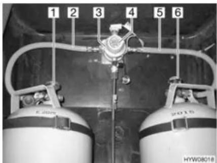
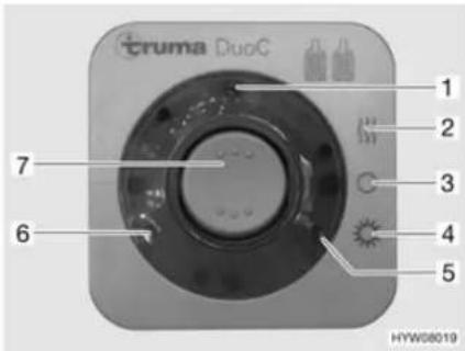
Fig. 108 DuoControl switching facility Fig. 109 Operating unit
Construction of the unit
The DuoControl switching facility consists of a reversing valve (Fig. 108,3) and an operating unit (Fig. 109). The reversing valve is installed between the gas tubes (Fig. 108,2 and 5). The knob (Fig. 108,4) on the reversing valve is used to select which of the gas bottles is to be used as a primary bottle and which is to be used as a reserve bottle.
The reversing valve is equipped with the regulator defroster Eis-Ex. This prevents damage to the gas system during the winter months.
Only the electrical functions can be switched at the operating unit (Fig. 109). The regulator taps on the gas bottles (Fig. 108,1 and 6) must be opened manually.
The reversing valve provides a constant gas pressure, regardless of which gas bottle is being drawn upon. The two indicator lamps on the operating unit indicate the level of the primary bottle. When the green indicator lamp (Fig. 109,6)
illuminates, the primary bottle is full. When the red indicator lamp (Fig. 109,5) illuminates, the primary bottle is empty. In this case, the reserve bottle is used for the gas supply.
Operating modes The DuoControl switching facility has two operating modes:
- Winter operation "On and heating"
- Summer operation "On"
Putting into operation:
■ Open the regulator taps on the gas bottles (Fig. 108,1 and 6).
■ Use the knob (Fig. 108,4) on the reversing valve (Fig. 108,3) to select the gas bottle which is to be the primary source of gas (primary bottle). Always turn the knob as far as it will go.
■ Switch on the DuoControl switching facility at the operating unit (Fig. 109). To do so, set the rocker switch (Fig. 109,7) to winter operation "On and heating" (Fig. 109,2) or to summer operation "On" (Fig. 109,4). The reversing valve is now deaerated. The yellow indicator lamp (Fig. 109,1) illuminates if the winter operation has been selected and the regulator defroster is activated.
Switching off:
■ Set the rocker switch (Fig. 109,7) to "O" (Fig. 109,3). The yellow indicator lamp (Fig. 109,1) goes out.
■ Close the regulator taps on the gas bottles (Fig. 108,1 and 6).
Remote display
The indicator lamps on the operating unit (Fig. 109,5 and 6) indicate in the vehicle interior whether the primary bottle is ready for operation.
Changing gas bottles
If the green indicator lamp (Fig. 109,6) stops illuminating during operation and the red indicator lamp (Fig. 109,5) illuminates, the gas bottle selected as primary bottle is empty and needs to be changed. The reserve bottle continues supplying the gas appliances with gas.

When changing gas bottles, do not smoke or create any open fire.
Changing gas bottles:
■ Close the regulator tap on the empty gas bottle.
■ Unscrew the gas tube of the gas bottle.
■ Connect the full gas bottle to the gas tube.
■ Open the regulator tap on the gas bottle.
■ Set the knob on the reversing valve with a half-turn, so that the newly replaced gas bottle will serve as a reserve bottle.
Chapter overview
This chapter contains instructions regarding the electrical system of the vehicle.
The instructions address the following topics:
- safety
● explanations of terms relating to the battery - 12 V power supply
- living area battery
- loading the batteries
- AC converter
• auxiliary charging unit - transformer/rectifier
panel - 240 V power supply
- connection to the 240 V power supply
- fuse rating
The operation of the electrical appliances of the housing body is described in chapter 10.
9.1 General safety instructions

▶ Only allow qualified personnel to work on the electrical system.
All electronic devices (e.g. mobile telephones, radios, televisions or DVD players) which have been retrofitted to the vehicle and are operated during the journey must have certain features: These are the CE certification, the EMC inspection (electromagnetic compatibility) and the "E1" inspection.
Only in this way can the functional reliability of the vehicle be ensured. Otherwise the airbag may be triggered or interference to the on-board electronics may result.
The vehicle is a safe place during a storm (Faraday cage). However, to protect the electrical devices, disconnect the 240 V connection and retract the antennae as a precaution.
9.2 Terms
Off-load voltage
The off-load voltage is the voltage of the battery in idle condition, i. e. no current is consumed and the battery is not being charged.
Closed circuit current
Some electrical appliances, such as the clock and the indicator lamps, require continuous electric current, for this reason they are referred to as inactive appliances. This closed circuit current flows even if the 12 V power supply has been switched off.
Total discharge
Total discharge of the battery is imminent, if a battery is completely discharged by an active appliance and by closed circuit current.

▷ Total discharge damages the battery.
Capacity Capacity refers to the amount of electricity which can be stored in a battery.
The capacity of a battery is given in ampere hours (Ah). If a battery possesses a capacity of 80 Ah, then the battery can dispense a current of 1 A for 80 hours or a current of 2 A for 40 hours.
External influences such as temperature may alter the storage capacity of the battery.
9.3 12 V power supply

To disconnect all electrical 12 V appliances from the power supply, disconnect the living area battery from the 12 V power supply via the panel.
When the vehicle is not connected to the 240 V power supply or the 240 V power supply is switched off, the living area battery supplies the living area with 12 V DC. The living area battery has a limited power supply only. For this reason, electrical appliances such as the radio and the lights should not be operated for a long time without using the 240 V power supply.
When the vehicle engine is running, the vehicle alternator recharges the living area battery and the starter battery.
The 12 V power supply can be cut off with the 12 V main switch on the panel. Depending on the model, the heater, basic light/entrance step and reserve 4 or only the electrical entrance step remain on standby. The refrigerator is then only operated with 12 V if the vehicle engine is running. This helps to prevent the living area battery from being run down too quickly.
9.3.1 Living area battery

Prior to commencing a journey ensure the living area battery is fully charged. For this reason charge the living area battery for at least 20 hours before commencing the journey.
During the trip, use every opportunity to charge the living area battery.
▶ Charge the living area battery for at least 20 hours after the journey.
▶ Charge the battery for at least 20 hours before laying up.
Use the charger module provided on the transformer/rectifier to charge the living area battery. When charging externally, use a regulated charger that is suitable for the battery type and the capacity of the living area battery.
For long periods of inactivity (4 weeks or more), either disconnect the living area battery from the 12 V power supply via the panel or recharge it regularly.
When the living area battery is changed, only use batteries of the same type.
When changing the living area battery, use only batteries which meet the minimum capacity of the charger. Observe the separate instruction manual for the charger. Lower-capacity batteries will generate a great deal of heat when they are charged. Danger of explosion!
Before disconnecting or connecting the terminals of the battery, switch off the vehicle engine as well as the 240 V and 12 V power supplies and all appliances. Danger of short circuit!
▷ If the starter battery or living area battery are disconnected, do not apply the ignition. Danger of short circuit!
Appliances with a maximum of 10 A can be connected to the sockets of the 12 V power supply system.

The battery is maintenance-free. Maintenance-free means:
It is not necessary to check the acid level.
It is not necessary to lubricate the battery poles.
It is not necessary to refill the distilled water.
Even a maintenance-free battery must be charged regularly.
Position
The living area battery is installed in the double floor and can be accessed via an external flap on the right of the vehicle.
Discharging
The living area battery is discharged by the closed circuit current which some electrical appliances continuously require.

▷ Total discharge damages the battery.
▷ Recharge battery in good time.
The self-discharge rate of the battery is dependant on temperature. At 20 to 25 °C the self-discharge rate is approx. 3 % of the capacity per month. The self-discharge rate will increase with rising temperatures: At 35 °C the self-discharge rate is approx. 20 % of the capacity per month.
During periods of low external temperatures, the battery will lose part of its capacity.
An older battery no longer has the complete capacity available.
The higher the number of active electrical appliances, the faster the energy of the living area battery is consumed.

Appliances such as the safety/drainage valve, charger, solar charge regulator and panel consume approx. 20 mA to 65 mA of electricity from the battery capacity, even when the 12 V main switch is turned off. Therefore disconnect the living area battery from the 12 V power supply via the panel, if the vehicle will not be used for a long period of time.
9.4 Charging the living area battery and starter battery

The acid in the battery is poisonous and corrosive. Any contact with the skin or the eyes is to be avoided.
In the case of charging with an external charger there is danger of explosion. Only charge the battery in a well ventilated area and away from naked flames or possible sources of sparks.
▶ Always remove the living area battery or the starter battery from the vehicle when charging them using an external charger.

Do not connect the battery cables to the wrong poles.
If the starter battery or living area battery are disconnected, do not apply the ignition. Danger of short circuit!
Before disconnecting or connecting the terminals of the battery, switch off the vehicle engine as well as the 240 V and 12 V power supplies and all appliances. Danger of short circuit!
Before charging the battery, check whether the external charger is approved for the battery type.
Observe the instruction manuals for the base vehicle and the charger.
▷ Irreparable damage to the living area battery will result if it is overcharged.
The starter battery can only be fully charged with an external charger. If a 240 V power supply is used, the transformer/rectifier charges the starter battery with a float charge only. Even in mobile operation, the vehicle engine alternator is not capable of completely charging the starter battery.
9.4.1 Charging using a 240 V power supply
If the vehicle is connected to the 240 V power supply, the living area battery and the starter battery are automatically charged by the charger module on the transformer/rectifier. The starter battery is only charged with a float charge. The charging current is adapted to suit the charging condition of the battery. This ensures that it is not possible to overload the battery.
To make use of the maximum output from the charger module on the transformer/rectifier, switch off all electrical appliances during charging.
9.4.2 Charging using the vehicle engine
When the vehicle engine is running, the vehicle alternator recharges the living area battery and the starter battery. When the vehicle engine is switched off, the batteries are automatically disconnected from one another by a relay in the transformer/rectifier. This prevents the starter battery from being run down by electrical appliances in the living area. The starting capability of the vehicle is thus preserved. The charging condition of the living area battery or the starter battery can be read on the panel.
9.4.3 Charging with an external charger
When charging the living area battery and the starter battery with an external charger, proceed as follows:
■ Turn off the vehicle engine.
■ Switch off 12 V main switch on the panel. The indicator lamp will go off.
■ Disconnect the living area battery from the 12 V power supply.
■ Disconnect the mains plug from the transformer/rectifier.
■ Switch off all gas appliances, all gas isolator taps and close the regulator tap on the gas bottle.
■ There is a danger of short circuit when disconnecting the battery poles. For this reason, first disconnect the negative terminal on the living area battery or the starter battery and then the positive.
■ Remove the living area battery or the starter battery from the vehicle.
■ Check that the external charger is turned off.
■ Connect the external charger to the living area battery or the starter battery. Pay attention to the polarity: First connect the positive terminal "+" to the positive pole of the battery, then connect the negative terminal "-" to the negative pole of the battery.
■ Switch on the external charger.
■ See the instructions for use of the connected charger for information concerning charge period required for the battery.
■ See the specifications on the battery for information concerning its strength.
■ Disconnect the external charger in reverse order.
9.5 AC converter

Do not cover the ventilation slots. Danger of overheating!

Also read the manufacturer's instruction manual.
Some models have a converter installed in the vehicle.
The AC converter supplies the 240 V sockets with voltage. When the vehicle is not connected to the 240 V supply, the connected battery supplies the voltage.
The battery has a limited power supply only. For this reason, the electrical appliances should not be operated for a long time without using the 240 V power supply.
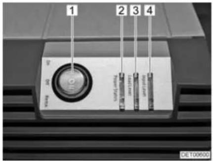
Fig. 110 Displays and operating controls
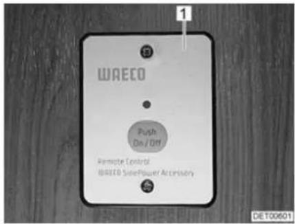
Fig. 111 External switch
The converter can be switched to two operating modes with the main switch (Fig. 110,1):
- I "On" = unit permanently switched on.
- II "Remo." = unit can be switched on and off at the external switch (Fig. 111,1).
The LEDs show the operating mode "Power Status" (Fig. 110,2), the load range "Load Level" (Fig. 110,3) and the voltage range "Input Level" (Fig. 110,4).
9.6 Auxiliary charging unit

Do not cover the ventilation slots. Danger of overheating!
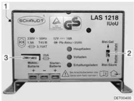
1 Mains switch (on rear side of unit)
2 Battery selector switch (lead acid/dry-fill option)
3 Fuse
Fig. 112 Auxiliary charging unit
The auxiliary charging unit (Fig. 112) supports the transformer/rectifier's charging performance. Therefore, do not switch off the auxiliary charging unit.
Position The auxiliary charging unit is fitted next to the transformer/rectifier.
9.7 Transformer/rectifier (EBL 220)

Do not cover the ventilation slots. Danger of overheating!

▷ Depending on the model, not all slots for the fuses are occupied.
▶ Further information can be obtained in the device manufacturer's instruction manual.
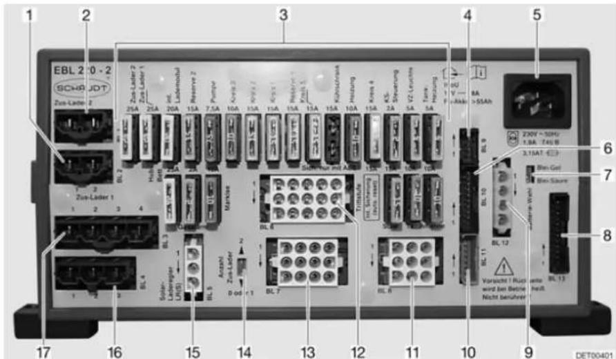
Fig. 113 Transformer/rectifier (EBL 220)
1 Connections BL 2 - auxiliary charging unit 1
2 Connections BL 1 - auxiliary charging unit 2
3 F I a t f u s e s
4 Connections BL 9 - solar charge regulator
5 Mains connection 240 V
6 Connections BL 10 - panel
7 Battery selector switch, lead acid/dryfill option
8 Connections BL 13 - panel
9 Connections BL 12 - sensor for living area battery D+
10 Connections BL 11 - panel
11 Connections BL 8 - entrance step, TV, antenna
12 Connections BL 6 - heater, water pump, spare
13 Connections BL 7 - awning, tank heater, awning light
14 Selector switch for the number of auxiliary charging units
15 Connections BL 5 - solar charge regulator
16 Connections BL 4 - refrigerator from starter battery
17 Connections BL 3 - refrigerator
Functions The transformer/rectifier has the following functions:
- The transformer/rectifier charges the living area battery. The transformer/rectifier charges the starter battery with a float charge only.
- The transformer/rectifier monitors the voltage in the living area battery.
- The transformer/rectifier distributes the current to the 12 V circuits and secures them. Devices with a maximum of 10 A can be connected to the sockets.
- The transformer/rectifier contains connections for a solar charge regulator, an auxiliary charging unit as well as other control and monitoring functions.
- When the engine is turned off, the transformer/rectifier separates the starter battery electrically from the living area battery. This prevents the 12 V living area appliances from discharging the starter battery.
The transformer/rectifier only works in conjunction with a panel.
When the transformer/rectifier is subject to a heavy load, the fitted charger module reduces the charging current. This protects the charger from overheating. The transformer/rectifier is subject to a heavy load when e.g. an empty living area battery is being charged, additional electrical appliances are turned on and the ambient temperatures are high.
Position
The transformer/rectifier (Fig. 113) is installed in the double floor. It can be accessed via floor flap in the entrance area.
9.7.1 Battery separation

The safety/drainage valve will open after the activation of the battery separation. The water flows out of the boiler. When the battery separation is deactivated again, close the safety/drainage valve of the boiler by hand.
Also switch off a refrigerator with automatic power selection system. The refrigerator will otherwise switch to gas operation.
After deactivation of the battery separation, it may be necessary to reset the date and time. The remaining settings will be saved at the activation of the battery separation and will be maintained.
The battery separation disconnects all the living area 12 V appliances, even the safety/drainage valve. This prevents the living area battery from slowly discharging if the vehicle is not used for a longer period of time (e.g. temporary lay-up).
The batteries can still be charged by the transformer/rectifier when the battery separation is activated.
Activating/deactivating See section 9.8.2.
9.7.2 Battery selector switch

If the battery selector switch is set incorrectly, there is the danger of the formation of detonating (oxy-hydrogen gas). Danger of explosion!

▷ Incorrect setting of the battery selector switch damages the living area battery.
The factory settings of the battery selector switch must not be changed.
The battery selector switch is used to set the charger module in the transformer/rectifier to the type of living area battery installed in the vehicle ("lead acid" or "dryfill" battery).
9.7.3 Battery monitor

▷ You must fully recharge a discharged living area battery as soon as possible.
The battery monitor in the transformer/rectifier monitors the voltage in the living area battery.
If the battery voltage falls below 10.5 V, the battery monitor in the transformer/rectifier switches off all of the 12 V appliances, excluding the safety/drainage valve.
A refrigerator with automatic power selection system switches to gas operation.
Measures:
■ Switch off all electrical appliances that are not absolutely essential at the corresponding switch.
If necessary, use the 12 V main switch to switch the 12 V power supply back on for a short while. This is only possible, however, when the battery voltage is above 11 V. If the voltage is below this level, the 12 V power supply cannot be switched on again until the living area battery has been recharged.
9.7.4 Charging the battery
When the vehicle engine is running, the vehicle alternator recharges the living area battery and the starter battery. When the vehicle engine is switched off, the batteries are automatically disconnected from one another by a relay in the transformer/rectifier. This prevents the starter battery from being run down by electrical appliances in the living area. The starting capability of the vehicle is thus preserved. The charging condition of the living area battery or the starter battery can be read on the panel.
If the vehicle is connected to the 240 V power supply, the living area battery and the starter battery are automatically charged by the charger module on the transformer/rectifier. The starter battery is only charged with a float charge. The charging current is adapted to suit the charging condition of the battery. This ensures that it is not possible to overload the battery.
To make use of the maximum output from the charger module on the transformer/rectifier, switch off all electrical appliances during charging.
9.8 Panel MP 20-T

The luminance of the LEDs and the symbols adapts automatically to the ambient light.
The displays can only be called up if the 12 V power supply is switched on.
As soon as a button is pressed, the gauge is automatically illuminated. The display goes out 20 seconds after the last key has been pressed.
▶ Further information can be obtained in the manufacturer's instruction manual.
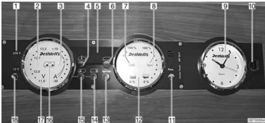
Fig. 114 Panel MP 20-T
1 230 V indicator lamp
2 Volt symbol
3 Ampere symbol
4 Interior temperature button
5 Digital display
6 External temperature button
7 Water tank symbol
8 Waste water tank symbol
9 Clock gauge
10 Lock
11 Reserve button
12 Tanks gauge
13 Tanks button
14 Living area battery button
15 Starter battery button
16 Symbol for starter battery and living area battery
17 Batteries gauge
18 Button for 12 V power supply (12 V main switch)
9.8.1 240 V indicator lamp
The 240 V indicator lamp (Fig. 114,1) illuminates whenever line voltage is available at the transformer/rectifier input.
9.8.2 12 V main switch
The 12 V main switch (Fig. 114,18) switches the panel and the 12 V power supply of the living area on and off.
Exception: Heater, safety/drainage valve, basic light (lighting in the entrance area) and entrance step remain operational.
Switching on:

■ Briefly press the "12 V" button (Fig. 114,18). The 12 V living area power supply is switched on. The "12 V" indicator lights up.
If, after switching on, the "11.0" LED of the volt indicator and the "V" volt symbol (Fig. 114,2) in the batteries gauge (Fig. 114,17) flash, the voltage of the living area battery is too low. Charge battery.
If, after switching on, the "12 V" indicator, the symbol for the living area battery (Fig. 114,16) and the "V" volt symbol (Fig. 114,2) flash three times, battery separation is activated. Deactivate battery separation.
Switching off:
■ Briefly press the "12 V" button (Fig. 114,18). The 12 V living area power supply is switched off. The "12 V" indicator goes out.
Activating battery disconnection (transformer/rectifier without battery cut-off switch):
Deactivating battery disconnection (transformer/rectifier without battery cut-off switch):

■ Switch off 12 V power supply.
■ Press button for living area battery (Fig. 114,14) and hold it down for approx. 10 seconds. The "V" volt (Fig. 114,2) and "A" ampere (Fig. 114,3) symbols flash three times. The living area battery is disconnected from the 12 V power supply.
■ Press the "12 V" button (Fig. 114,18) and hold it down for approx. 5 seconds. The "V" volt symbol (Fig. 114,2) flashes three times. The living area battery is connected to the 12 V power supply. The indicator lights up after approx. 2 seconds.
When leaving the vehicle, switch off the 12 V main switch. This prevents any unnecessary discharge of the living area battery.
Appliances such as the safety/drainage valve, charger, solar charge regulator and panel consume approx. 20 mA to 65 mA of electricity from the battery capacity, even when the 12 V main switch is turned off. Therefore disconnect the living area battery from the 12 V power supply, if the vehicle will not be used for a long period of time.
9.8.3 Batteries gauge
The voltage and charging/discharging of the living area battery or the starter battery voltage can be indicated using the batteries gauge.
Displays:
■ Press button for living area battery "☐" (Fig. 114,14). The "V" volt symbol (Fig. 114,2) lights up. Depending on whether the battery is being charged or discharged, the "A" ampere symbol lights up white or red respectively. The battery voltage and current of the living area battery are displayed using the LEDs in the gauge.
■ Press button for starter battery "☐" (Fig. 114,15). The "V" volt symbol (Fig. 114,2) lights up. The battery voltage of the starter battery is displayed using the LEDs in the gauge.
The tables below will help you interpret the statuses displayed on the panel.
Volt indicator (blue)
| 1 LED | 2 LEDs | 3 LEDs | 4 LEDs | 5 LEDs | 6 LEDs | 7 LEDs | 8 LEDs |
| < 11.0 V | 11.5 V | 12.0 V | 12.2 V | 12.5 V | 12.7 V | 13.0 V | >13.5 V |
Danger of total discharge (battery alarm)
| Battery voltage (values during operation) | Mobile operation (vehicle moving, no 240 V connection) | Battery operation (vehicle stationary, no 240 V connection) | Power operation (vehicle stationary, 240 V connection) |
| 11 V or less 1) | 12 V power supply overload | If appliances are switched off: Battery flatIf appliances are switched on: Battery overload | 12 V power supply overload |
| The battery is not charged by the alternator, the alternator's regulator is defective | The battery is not charged by the transformer/rectifier, the transformer/rectifier is defective | ||
| 11.5 V to 13 V 12 V | power supply overload 2) | Normal range 12 V | power supply overload 2) |
| The battery is not charged by the alternator, the alternator's regulator is defective | The battery is not charged by the transformer/rectifier, the transformer/rectifier is defective | ||
| Over 13.5 V Battery | is being charged (main charge) | Occurs only briefly after charging | Battery is being charged (main charge) |
1) The battery guard switches all the appliances off (at 10.5 V).
2) If the voltage does not exceed this range for several hours.
| Values for off-load voltage Charging condition of the battery | |
| Less than 11 V Totally discharged | |
| 12.0 V 0 % (discharged) | |
| 12.2 V 25 % | |
| 12.3 V 50 % | |
| 12.5 V 75 % | |
| More than 12.8 V Full | |

▷ Total discharge causes irreparable damage to the battery.
Ampere indicator (blue)
| 1 LED | 2 LEDs | 3 LEDs | 4 LEDs | 5 LEDs | 6 LEDs | 7 LEDs | 8 LEDs |
| Discharging with: Charging with: | |||||||
| >30 A | >10 A | >3 A | >1 A | Approx. 0 A | >1 A | >3 A | >10 A |
| Current displayed System status "A" ampere symbol | ||
| -30 A to -10 A Battery is being heavily discharged | Lights up red | |
| -10 A to -1 A Battery is being discharged | Lights up white | |
| 0 A Battery current is low or 0 A | Lights up white | |
| +1 A to +10 A Battery being charged Lights up white | ||
9.8.4 Tank gauge
The water and waste water quantities can be indicated using the tank gauge.
Displays:
■ Press tanks button "☐" (Fig. 114,13). The water tank "☐" (Fig. 114,7) and waste water tank "(Fig. 114,8) symbols light up. The fill level of the water tank (left-hand scale) and the waste water tank (right-hand scale) are indicated using the LEDs in the gauge.
The table below will help you interpret the levels displayed on the panel.
Level indicator (blue)
| 1 LED | 2 LEDs | 3 LEDs | 4 LEDs | 5 LEDs | 6 LEDs | 7 LEDs | 8 LEDs |
| 25 % | 50 % | 75 % | 100 % | ||||
9.8.5 Alarms

Battery alarm
The alarm functions are only active when the corresponding display is called up. Perform checks regularly. It is best to perform checks in the morning, before the 12 V appliances are switched on.
The "V" volt symbol (Fig. 114,2) and the "11.0" LED flash as soon as the battery voltage falls below 11 V (measured during operation) and there is the threat of a total discharge.


Measures:
▷ Total discharge damages the battery.
If the battery voltage falls below 10.5 V, the battery monitor in the transformer/rectifier switches off all of the 12 V appliances, excluding the safety/drainage valve.
■ When the battery alarm comes on, switch off the appliances and charge the battery, either by mobile operation or by connection to a 240 V power supply.
Tank alarm
The water tank symbol " (Fig. 114,7) or waste water tank symbol " (Fig. 114,8) flashes when the water tank is empty or the waste water tank is full.

If, when the fill levels are called up, the LEDs in the scale flash in addition to the tank symbol, a sensor error has occurred. Clean tank sensors.
Measures: ■ Fill water tank or empty waste water tank.
9.8.6 Temperature display
The internal and external temperatures can be indicated using the digital display (Fig. 114,5).
Displays:
■ Press internal temperature button "☐" (Fig. 114,4). The internal temperature is displayed.
■ Press external temperature button "☐" (Fig. 114,6). The external temperature is displayed.
9.8.7 Clock gauge
The clock gauge (Fig. 114,9) displays the time. The clock has its own battery and is not connected to the 12 V power supply.
Detach the clock if the battery needs to be replaced or the clock needs to be set.
Detaching clock:
■ Turn lock (Fig. 114,10) one quarter turn. The lock is released.
■ Detach clock by pulling forwards.
Fitting clock:
■ Install clock.
■ Lightly press lock (Fig. 114,10) and turn a quarter turn.
■ Check lock by lightly pulling on the clock.
9.8.8 Switch for tank heater
The tank heater can be turned on and off using the "Res" button (Fig. 114,11).
Switching on:
■ Press "Res" reserve button (Fig. 114,11). The "Res" symbol lights up.
Switching off:
■ Press "Res" reserve button (Fig. 114,11). The "Res" symbol goes out.

The switch status is saved when the 12 V power supply is switched off. This means: If the tank heater was on when the 12 V power supply was switched off, the heater is also switched on when the 12 V power supply is switched back on.
9.9 240 V power supply

▶ Only allow qualified personnel to work on the electrical system.
The 240 V power supply provides electricity for:
- sockets with earth contact for appliances with maximum 16 A
- refrigerator
- transformer/rectifier
- air conditioning unit
The electrical appliances connected to the 12 V power supply of the living area are supplied with voltage by the living area battery.
Connect the vehicle to an external 240 V power supply system as often as possible. The charger module in the transformer/rectifier automatically charges the living area battery. In addition to this, the starter battery is charged with a float charge.
The air conditioning unit and other optional devices are fuse-protected by their own two-pole automatic circuit breaker (16 A).
9.9.1 240 V connection

The external 240 V power supply must be protected by fuse with a fault current protection switch (FI-switches, 30 mA).

For the connection points on camp sites (camping distributors) highly sensitive fault current protection switches (FI-switches, 30 mA) are obligatory.
The vehicle can be connected to an external 240 V power supply. The cable may have a length of maximum 25 m.
9.9.2 Power cable for external 240 V connection

▶ Completely unwind the cable on cable drums to prevent overheating.
Power cable
- Three-core (3 x 2.5 mm ^2 ) flexible rubber sheathed cable
• Maximum 25 m in length - 1 plug with earth contact
● 1 socket with earth contact (plug-in devices according to EN 60309)
Connection possibilities
For your power cable, we recommend using a CEE connection cable with a CEE plug and coupling. If this type of connection is not feasible, we recommend the following combination with a safety plug:
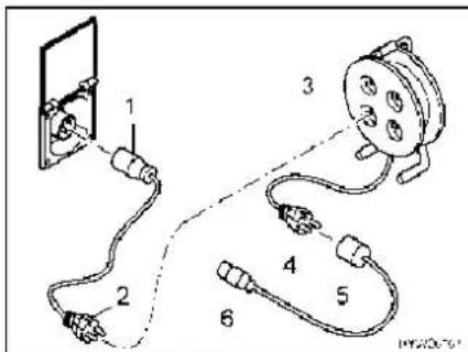
Fig. 115 Connection possibilities 240 V connection
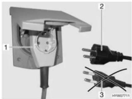
Fig. 116 Connecting an angled connector with socket
- Adapter cable: CEE 17 socket with earth contact (Fig. 115,1) – plug with earth contact (Fig. 115,2)
- Cable reel: Socket with earth contact (Fig. 115,3) – plug with earth contact (Fig. 115,4)
- Adapter cable: CEE 17 socket with earth contact (Fig. 115,5) – plug with earth contact (Fig. 115,6)

When using a CEE 17 angled connector with rear socket (Fig. 116,1) only use a rubberised and sealed IP 44 socket with earth contact (Fig. 116,2). Do not use sockets without earth contact (Fig. 116,3). Danger of electrocution!
Depending on the design, the flap for the 240 V connection is designated with the symbol "#.
Connecting the power cable:
■ Open external flap.
■ Depending on the design, tilt the cover upwards.
■ Insert connector.
▷ Depending on the design, disconnect the connector before removing it.

9.10 Fuses

▶ Only replace defective fuses when the cause of the defect is known and has been remedied.
▶ Replace defective fuses only after the power supply has been turned off.
▶ Never bridge or repair fuses.
9.10.1 12 V fuses
The appliances connected to the 12 V power supply in the living area are fused individually. The fuses are accessible at different positions in the vehicle.
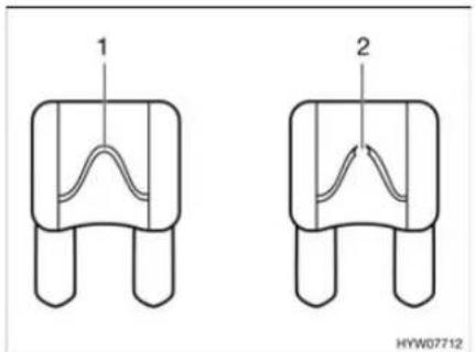
Fig. 117 12 V fuse
1 Unbroken fuse element
2 Broken fuse element
An intact 12 V fuse can be detected by the unbroken fuse element (Fig. 117,1). If the fuse element is broken (Fig. 117,2), change the fuse.

Before changing the fuses, check the rating and colour of the fuses in question. When changing fuses, use only fuses with the same ratings as the fuses fitted at the factory.
Fuses on the starter battery
The fuses are fitted in the engine compartment above the starter battery.
Depending on the model, the type and rating of the fuses may differ to those shown here.
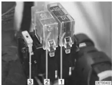
natural_image
Close-up of three transparent electrical contactors labeled 1, 2, and 3, mounted on a surface (no visible text or symbols beyond labels)Fig. 118 Fuses on the starter battery
1 Jumbo flat fuse 60 A/blue (for the transformer/rectifier)
2 Jumbo flat fuse 20 A/yellow (for refrigerator and charging line)
3 Flat fuse 2 A/grey (for alternator D+)
Fuses on the living area battery
The fuses are fitted next to the living area battery.
Depending on the model, the type and rating of the fuses may differ to those shown here.
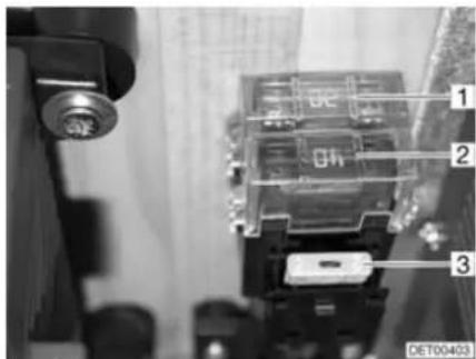
Fig. 119 Fuses on the living area battery
1 Jumbo flat fuse 20 A/yellow (for the optional device)
2 Jumbo flat fuse 60 A/blue (for the transformer/rectifier)
3 Flat fuse 2 A/grey
(for battery charger sensor)
Fuse for the Thetford toilet (swivel toilet)
The fuse is located in the locker wall of the Thetford cassette.
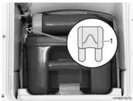
Fig. 120 Fuse for the Thetford toilet
1 Flat fuse 3 A/purple
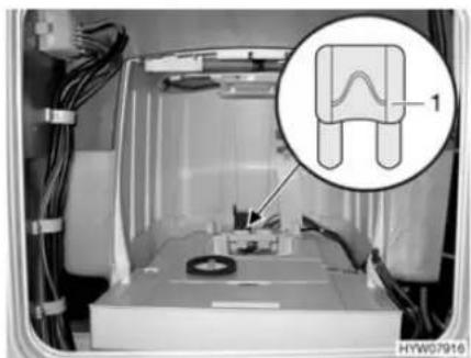
Fig. 121 Fuse for the Thetford toilet (alternative)
Changing:
■ Open the flap for the Thetford cassette on the outside of the vehicle.
■ Pull out the Thetford cassette completely.
■ Replace fuse (Fig. 120,1 or Fig. 121,1).
9.10.2 240 V fuse
Depending on the model and optional devices, the number of automatic circuit breakers may differ from the example shown here.
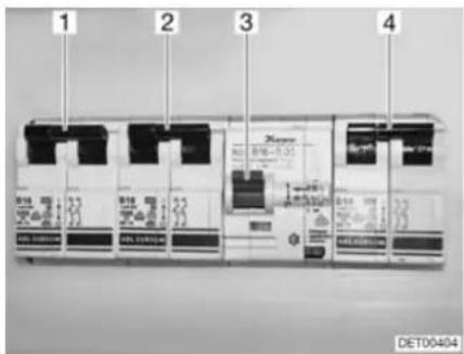
Fig. 122 240 V automatic circuit breakers
1 Automatic circuit breaker for the air conditioning unit
2 Automatic circuit breaker for the optional device
3 Fault current protection switch
4 Automatic circuit breaker 240 V connection
The 240 V connection is protected by a two-pole automatic circuit breaker (Fig. 122,4) (10 A).
Position Depending on the model, the automatic circuit breakers are installed in the wardrobe or rear garage.
Chapter overview
This chapter contains instructions regarding the appliances of the vehicle.
The instructions refer exclusively to the operation of the appliances.
Further information about the appliances can be found in the instruction manuals for the appliances, included separately with the vehicle.
The instructions address the following topics:
- heater
- boiler
- gas cooker
- gas oven
- microwave oven
- extractor hood
- refrigerator
• air conditioning unit - dishwasher
- vacuum cleaner
10.1 General

The heat exchanger of the Alde hot-water heater has to be replaced after 10 years. Only the manufacturer of the heater or an authorised specialist workshop is allowed to replace the heat exchanger. The operator of the heater must see to it that the parts are replaced.
For safety reasons, spare parts for pieces of heating appliances must correspond with manufacturer's instructions and be permitted by the manufacturer as a spare part. These spare parts may only be fitted by the manufacturer or an authorised specialist workshop.
▶ Further information can be obtained in the instruction manual for the respective appliance.

The heater, boiler, cooker, refrigerator and air conditioning unit are fitted depending on the model of the vehicle.
In this instruction manual a description is given only for the operation of the appliances and their particular features.
To operate gas appliances, first open the regulator tap on the gas bottle and the gas isolator tap corresponding to the appliance.
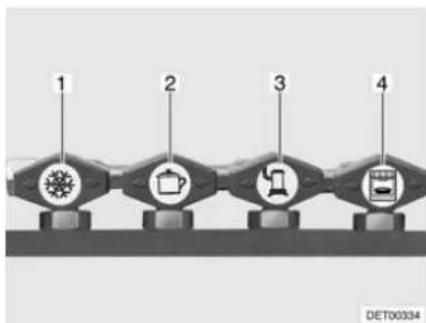
flowchart
graph LR
    A["1"] --> B["2"]
    B --> C["3"]
    C --> D["4"]
1 Refrigerator
2 C o o k e r
3 Heater/boiler
4 O v e n
Fig. 123 Symbols for the gas isolator taps
10.2 Alde hot-water heater

▶ Never let gas escape unburned due to danger of explosion.
▶ Never run the heater in gas operation when refuelling, on ferries or in the garage. Danger of explosion!
▶ Never operate the heater in gas operation in closed spaces (e.g. garages). Danger of poisoning and suffocation!

▷ Never run hot-water heater without heating fluid. Observe notes in chapter 13.
▷ Never drill holes in the floor. This might damage the hot-water pipes.
Do not use the space above and behind the heater as a storage compartment.

The circulating pump must always be turned on when the hot-water heater is in operation.
We recommend to bleed the heating system after the initial heater operation and to check the glycol content. Observe notes in chapter 13.
▷ When the heater is turned on, it starts with the last settings used.
For further information, see the separate manufacturer's instruction manual and observe the maintenance instructions found in chapter 13.
For further information about the use of the boiler see section "Boiler".
Initial start-up
When lighting the heater for the first time a small amount of smoke and odour will occur. Immediately set the operating switch of the heater to its highest position. Open doors and windows and ventilate well. Smoke and odour will disappear by themselves after a while.
Operating unit The operating unit is divided into two sections:
- Display (touch screen)
- Control buttons
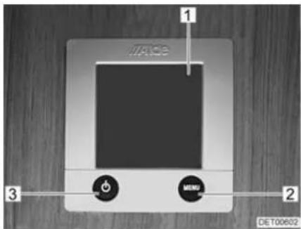
1 Display (touch screen)
2 "Menu" button
3 On/Off button
Fig. 124 Operating unit for hot-water heater

When no button is pressed, the operating unit automatically switches to home position after two minutes.
Changes to the settings are saved automatically after 10 seconds.
Control buttons The control buttons have the following functions:
| Pos. in Fig. 124 | Button Function |
| 2 MENU | Open adjustment menu |
| 3 |
Display The display (Fig. 124,1) is designed as a touch screen. Touching the symbols calls up the relevant function.
Start screen
The Start screen appears on the display after the heater is switched on. The Start screen contains the following information:
| Symbol Signification | |
| This symbol appears when the circulating pump is activated | |
| This symbol appears when a switching facility for gas cylinders is activated | |
| This symbol appears when a voltage of 240 V is present at the heater | |
| The internal temperature is displayed next to this symbol | |
| The external temperature is displayed next to this symbol if an external sensor is fitted | |
Adjustment menu
The "MENU" button calls up the adjustment menu. The meanings of the individual symbols are described in the following table.
The values can be increased or reduced via the "+" or "-" symbols.
| Symbol Signification | |
| Set the desired temperature of +5 °C to +30 °C | |
| Set the water temperature in the boiler | |
| Set the heat output in electrical operation | |
| Activate the function "Heating in gas operation" | |
| Call up the enabling menu for the tool menus | |
Tool menus
The various heater functions can be called up and adjusted via the tool menus. The arrow symbols are used to change between the menus. The meanings of the individual symbols are described in the manufacturer's instruction manual.
Selecting the operating mode
The hot-water heater can be operated with the following energy sources:
Gas operation
● 240 V electrical operation
● Gas and 240 V electrical operation
The operating mode is selected from the operating unit.
Selecting gas operation:
■ Press the "On" button next to the "△" symbol. The gas operation is activated.
■ Press the "+" button next to the "⚡" symbol until the desired heat output is reached.
Selecting 240 V electrical operation:

▷ Select the output level during 240 V electrical operation in such a way that it corresponds to the 240 V connection protection:
Level 1 (1050 W) at 6 A
Level 2 (2100 W) at 10 A
Level 3 (3150 W) at 16 A
Selecting gas and 240 V electrical operation:
■ Select gas operation and 240 V electrical operation on the operating unit.

If gas and 240 V electrical operation is selected and if the vehicle is connected to the 240 V power supply, then the hot-water heater at first only operates in 240 V electric operation. Only if the heat output is insufficient does the gas operation also automatically switch on.
The gas operation is only possible when the regulator tap on the gas bottle and the gas isolator tap are opened.
240 V electrical operation is only possible when the vehicle is connected to the 240 V power supply.
When the heater is turned on, it starts with the last set operating mode.
Switching on the heater:
■ Press "button. The Start screen appears in the display. The heater starts automatically.
Switching the heater off:
■ Press "button. The heater is turned off.
10.2.1 Alde heat exchanger

The heat exchanger only works when the vehicle engine is running.
▷ If the heat exchanger is not being used (as in the summer), the heat exchanger on the stopcock should be shut off.
The heat exchanger can be used to heat the living area of the vehicle during travel without operating the hot-water heater in the living area.
The heat exchanger is connected to the vehicle engine's cooling circuit and thus has the same function as the vehicle heater.
Heat output is set with the living area's heating regulator.
The heat exchanger stopcock is located directly on the exchanger.
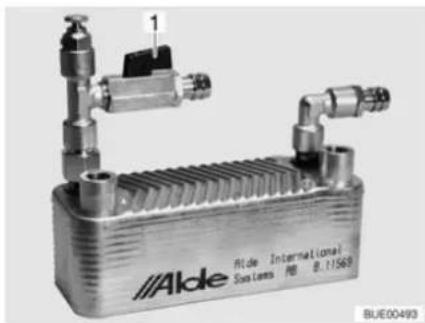
natural_image
Exterior view of a Alde industrial heat exchanger unit (no signage or text in focus)Fig. 125 Alde heat exchanger
Turning on:
■ Set stopcock handle (Fig. 125,1) parallel to the pipe.
Shutting off:
■ Set drain cock handle (Fig. 125,1) at a right angle to the pipe.
10.2.2 Alde auxiliary circulating pump

The auxiliary circulating pump works only if the heat exchanger has been installed and started, and the hot-water heater is running.
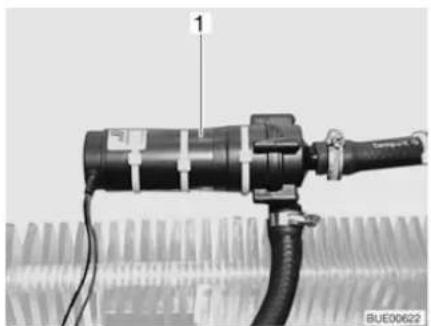
natural_image
Close-up of a mechanical device with a labeled component (1) and cable, no visible text or symbols on the main body.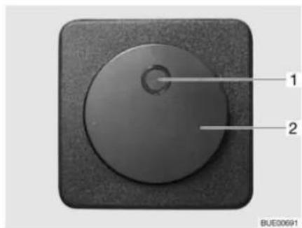
Fig. 126 Auxiliary circulating pump Fig. 127 Operating switch for auxiliary circulating pump
The auxiliary circulating pump (Fig. 126,1) can be used to heat the vehicle engine when parked.
The auxiliary circulating pump is connected to the vehicle engine's cooling circuit and thus functions as an engine heater.
The auxiliary circulating pump switch (Fig. 127,2) is located behind the front passenger's seat. The yellow indicator lamp (Fig. 127,1) illuminates when the pump is operated.
10.2.3 Setting the rotational speed of the circulating pump

The hot-water heater is equipped with a very powerful pump. Only operate the pump for approx. 5 minutes on full output when the system is emptied or the pipes are bled. Otherwise, this will increase wear; loud operating noises are the result.
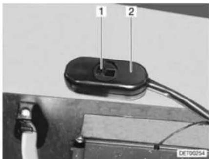
Fig. 128 Rotational speed reduction switch
The rotational speed of the circulating pump can be set with the sliding switch (Fig. 128,2). At a lower rotary speed, the operating sounds of the pump are quieter.
The sliding regulator is located in the hot-water heater area.
Setting the output:
■ Push sliding trap (Fig. 128,1) towards the right. The output is reduced.
■ Push sliding trap towards the left. The output is increased.
10.3 Independent vehicle heater

▶ Do not operate the independent vehicle heater in closed spaces. Danger of suffocation!
▶ Do not operate the independent vehicle heater at petrol stations. Danger of explosion!
The inside and the engine can be heated with the independent vehicle heater. The heating of the engine can be switched off.
The independent vehicle heater can be turned on and off manually or with a timer. The time for the heating to start can be exactly preselected from 1 minute to 24 hours. It is possible to program three switching on times, of which only one can be activated. The maximum permitted operation time is 60 minutes.
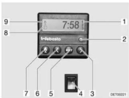
Fig. 129 Operating unit for independent vehicle heater
Switching on manually:
■ Press the button (Fig. 129,7). The heating mode is displayed by the symbol (Fig. 129,9). The fan will only be switched on when there is a coolant temperature of 30 °C.
Switching off manually:
■ Press the button (Fig. 129,7). The symbol (Fig. 129,9) goes off.
Switching on the engine heating:
■ Press the lower part of the switch (Fig. 129,4). Engine is preheated. The fan is switched on immediately.
Switching off the engine heating:
■ Press the upper part of the switch (Fig. 129,4). Engine stays cold.
Setting the time:
■ Press the button (Fig. 129,2). The time setting is displayed by the symbol (Fig. 129,8).
■ Set the time with the buttons (Fig. 129,3 and 6).
Programming heating start:
■ Press the button (Fig. 129,5).
■ Set the switching on time within ten seconds, with the buttons (Fig. 129,3 and 6).
Selecting programmed switching on time:
- Keep pressing button (Fig. 129,5) until the selected programme number (Fig. 129,1) appears in the display.
10.4 Alde boiler

▶ Never let gas escape unburned due to danger of explosion.
▶ Never run the boiler in gas operation when refuelling, on ferries or in the garage. Danger of explosion!
▶ Never operate the boiler in gas operation in closed spaces (e.g. garages). Danger of poisoning and suffocation!
The water in the boiler can be heated up to 65 °C. Risk of scalding!

▷ Never use boiler when empty.
▶ If the boiler is not being used, empty it if there is any risk of frost.
Only operate the boiler with the maximum temperature setting if you require a large quantity of warm water. This protects the boiler against the build-up of limescale.

▷ Dethleffs recommends that water from the boiler is not used as drinking water.
10.4.1 Switching the boiler on/off
The boiler is integrated in the hot-water heater. A separate operation is not possible. For operating the hot-water heater, see section 10.2.
10.4.2 Filling/emptying the boiler
The boiler can be supplied with water from the water tank.
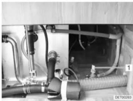
natural_image
Interior view of an industrial piping system with hoses and valves (no visible text or symbols)Fig. 130 Drain cock
Filling the boiler with water:
Emptying the boiler:
■ Close drain cock. Position the rocking lever (Fig. 130,1) horizontally.
■ Switch on 12 V power supply on the panel.
■ Set all the water taps to "Hot" and open them. The water pump is turned on. The warm water pipes are filled with water.
- Keep the taps open until the water flowing out of the taps has no bubbles in it. This is the only way to ensure that the boiler is full of water.
■ Close all water taps.
■ Switch off boiler.
■ Open all water taps and set to the central position.

■ Open drain cock (Fig. 130). To do so, set the rocking lever (Fig. 130,1) in a vertical position. The boiler is drained to the outside using the drain cock.
■ Check whether the water has been drained completely from the boiler (approx. 12.5 litres).
▶ Further information can be obtained in the manufacturer's instruction manual.
10.5 Cooker

▶ Never let gas escape unburned due to danger of explosion.
Before using the cooker make sure that there is sufficient ventilation. Open windows or the skylight.
▶ Do not use gas cooker or gas oven for heating.
▶ Always protect your hands with cooking gloves or potholders when handling hot pots, pans and similar items. There is a risk of injury.
10.5.1 Gas cooker

During activation and operation of the gas cooker, no flammable objects or highly inflammable objects such as dishcloths, napkins etc. must be near the gas cooker. Fire hazard!
The process of ignition must be visible from above and must not be covered by cooking pans placed on the cooker.
▶ Depending on the model, the gas cooker lid is held closed by a spring. When closing there is danger of getting injured!

Do not use the glass gas cooker lid as a hob.
Do not close the gas cooker lid while the gas cooker is in operation.
Do not apply pressure on the gas cooker lid when it is closed.
Do not place hot cooking pans on the gas cooker lid.
Keep the gas cooker lid open after cooking until the burners are cool. Otherwise the glass plate could shatter.
Do not place hot objects such as cooking pans on the sink cover. The plastic can become deformed.

▶ Only use pots and pans whose diameter is appropriate for the gas cooker burners.
When the flame goes out, the thermocouple automatically cuts the gas supply.
▶ Further information can be obtained from the separate instruction manual "Gas cooker".
The vehicle kitchen unit is fitted with a three-burner gas cooker.
The gas cooker is equipped with electronic ignition.
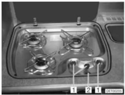
natural_image
Interior view of a gas stove with four numbered outlets (1, 2, 1) and no visible text or symbols on the stove itself.Fig. 131 Operating controls for gas cooker
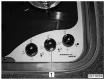
natural_image
Close-up of a vintage industrial control panel with rotary buttons and a dial (no readable text or symbols)Fig. 132 Operating controls for gas cooker (alternative)
Switching on:
■ Open the regulator tap on the gas bottle and the gas isolator tap "Cooker".
■ Open the gas cooker lid.
■ Turn the control knob (Fig. 131,1 or Fig. 132,1) on the burner you wish to use to the ignition position (large flame).
■ Press the control knob down and hold it.
■ Press the rocker switch (Fig. 131,2) if necessary until there is a flame.
■ Once the flame is burning, the control knob must be held down for 10 to 15 seconds, until the thermocouple automatically keeps the gas supply open.
■ Release the control knob and turn to the desired setting.
Switching off:
■ Turn the control knob to the 0-position. The flame fades.
■ Close the gas isolator tap "Cooker" and the regulator tap on the gas bottle.
10.5.2 Gas oven

▶ Keep the ventilation openings on the gas oven open at all times.
There must be no flammable objects near the gas oven when it is being lit.
The oven flap must remain open when it is being lit.
▶ If ignition has not taken place, repeat the entire procedure. If necessary, check if there is gas and/or current in the gas oven.
▶ If the gas oven still does not work, close the gas isolator tap and notify your service centre.
If the burner flame is accidentally extinguished, switch the oven off and leave the burner off for at least 1 minute. Then ignite it again.
▶ When grilling, pull out the heat guard and leave the flap fully open.

Before using the gas oven for the first time run it for 30 minutes at maximum temperature without any contents.
When the flame goes out, the thermocouple automatically cuts the gas supply.
▶ Further information can be obtained from the separate instruction manual "Gas oven".
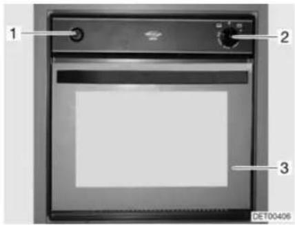
Fig. 133 Gas oven
Switching on:
■ Open the regulator tap on the gas bottle and the gas isolator tap "Oven".
■ Fully open the oven flap (Fig. 133,3).
■ Lightly press control knob (Fig. 133,2) and set to "☐" (oven) or "☐" (grill).
■ Press the control knob (Fig. 133,2) and hold it down for 5 to 10 seconds. Gas will stream into the burner.
■ Press the lighting switch (Fig. 133,1) repeatedly until there is a flame.
■ Once the flame is burning, the control knob must be held down for 10 to 15 seconds, until the thermocouple automatically keeps the gas supply open.
■ Release the control knob and turn to the desired setting.
Switching off:
■ Turn control knob (Fig. 133,2) to "○". The flame fades.
■ Close the gas isolator tap "Oven" and the regulator tap on the gas bottle.
10.5.3 Microwave oven

▶ Only qualified personnel may repair the microwave oven. Improper repairs can cause major risks to the user.
The protection device against the escape of microwave energy should never be removed.
▶ Use the microwave oven only if it has been properly installed.
▶ Only use the microwave oven when the door seal is free of damage.
▶ Never leave the microwave oven unattended when it is in operation.
▶ If there is smoke, keep the microwave oven closed, switch it off and interrupt the power supply.

Operate the microwave oven only with the rotary plate and the rotary cross in place.
▷ Use only crockery suitable for microwave use.

The microwave oven only functions with correct 240 V power supply. In the case of fluctuations of the voltage or of voltage below 230 V, the microwave oven switches itself off completely. Therefore, do not switch on additional 240 V appliances when the microwave oven is in operation. Particularly in southern countries it happens that the line voltage is described as having 230 V but it really does not amount to this value. So it may happen that the microwave oven cannot be operated in these countries.
▶ Further information can be obtained from the separate instruction manual "Microwave oven".
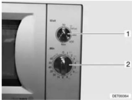
Fig. 134 Operating controls for microwave oven
Switching on:
■ Open the door and place foodstuffs into the cooking area.
■ Close the door. A clicking noise can be heard when it engages.
■ Select the output on the control knob (Fig. 134,1).
■ Select the cooking time with the control knob (Fig. 134,2). Cooking begins.
The end of the cooking process is signalled by a signal tone. The microwave oven will switch off automatically.
Switching off:
■ Open the door and remove foodstuffs.
10.5.4 Extractor hood
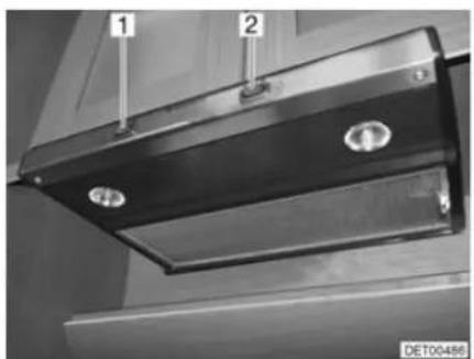
natural_image
Close-up of a black metal HVAC vent with two circular components, labeled 1 and 2 (no text or symbols on the vent itself)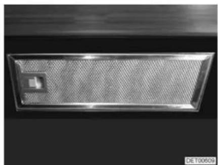
natural_image
Metallic rectangular object with a small square hole, possibly a vent or filter array (no text or symbols visible)Fig. 135 Extractor hood Fig. 136 Extractor hood (alternative)
The cooking area is equipped with an extractor hood. The two-level fan blows the cooking steam directly outside.
■ Use the switch (example: Fig. 135,1) to turn the extractor hood on and off.
■ Use the switch (example: Fig. 135,2) to turn the cooker lamps on and off.
10.6 Refrigerator
During the journey, only operate the refrigerator via the 12 V power supply. At high ambient temperatures the refrigerator is unable to reach its full cooling power. At high external temperatures, the full cooling power of the cooling unit is only guaranteed if the refrigerator is ventilated sufficiently. In order to achieve a better ventilation the refrigerator ventilation grill can be removed.

When leaving the vehicle, always mount the refrigerator ventilation grill. Otherwise water can enter during rain.
10.6.1 Refrigerator ventilation grill
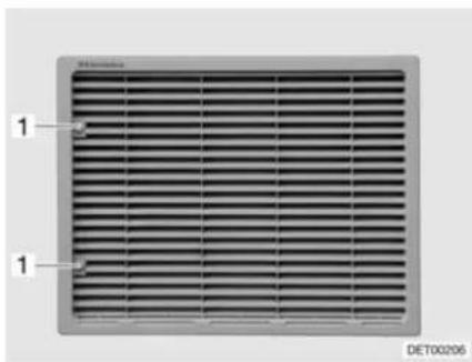
Fig. 137 Refrigerator ventilation grill
Removal:
■ Turn screw (Fig. 137,1) one quarter turn using a coin.
■ Remove refrigerator ventilation grill.
10.6.2 Operation (Dometic 7 series with automatic power selection and frame heater)
Operating modes
The refrigerator is equipped with automatic power selection (AES). The AES automatically selects the optimal energy source and regulates the refrigerator operation. Manual intervention to select the type of power is possible but not required.
The AES selects from the following types of power:
• Solar installation 12 V
- 240 V AC
12 V DC
Gas
Choosing the available energy source highest on the list.

Even when the 12 V power supply is switched off, a small electrical power flows which puts an extra load on the living area battery. Always switch off the refrigerator for a temporary lay-up.
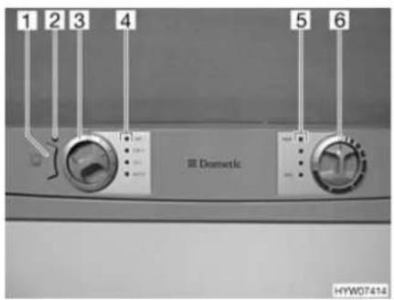
Fig. 138 Operating controls for the refrigerator (Dometic 7 series with AES and FH)
1 Frame heater (FH) button
2 Indicator lamp
3 Energy selector switch
4 Indicator lamps
5 Indicator lamps
6 Control knob for setting the temperature
240 V operation
If the 240 V power supply is connected, this energy source is selected as the first priority by the AES.
12 V operation
12 V operation is only selected by the AES if the vehicle's engine is running and the alternator supplies sufficient 12 V operating power.
Gas operation

▶ Never let gas escape unburned due to danger of explosion.
It is not permitted to operate the refrigerator with car gas.

▷ Open the regulator tap on the gas bottle and the gas isolator tap "Refrigerator".
If the 240 V power supply is not connected and the vehicle's engine is not running the AES selects the gas supply. When selecting gas operation the ignition fuse is opened automatically so gas can get into the burner. At the same time the electronic ignition is activated. If the gas flame is extinguished, e.g. by blast of wind, the ignition is activated immediately and re-ignites the gas. When the gas operation is faulty, the "GAS" indicator lamp (Fig. 138,4) flashes red.
Change-over between energy sources

▶ Open flames are prohibited at petrol stations. If the stop takes longer than 15 minutes, the refrigerator has to be turned off at the energy selector switch.
When changing over between the different power sources there are forced delays built in the AES. This means, that after a change-over to a new energy source the refrigerator can not be operated immediately. When changing over from 12 V operation to gas operation, a 15-minute delay is built in the AES. This prevents a change-over to gas operation when the vehicle is stopped briefly and the engine is switched off (e.g. stop to fill tank).
Refrigerating temperature control
When turned on the first time the refrigerator automatically selects the middle thermostat position. This position can be adjusted manually by using the control knob (Fig. 138,6). The indicator lamps (Fig. 138,5) show the selected thermostat position. The refrigerating temperature for the three types of energy is set with the control knob. It takes a few hours till the refrigerator reaches its
normal operating temperature. When changing over the operating mode the thermostat setting will be maintained. The refrigerating temperature is retained regardless of the type of power being used.
Frame heater (FH)

If the frame heater is switched on, it will always consume current. Therefore, switch off the frame heater if the vehicle engine is off and the vehicle is not connected to the 240 V power supply.
High external temperatures and high humidity can cause drops of water to form on the metal frame of the freezer compartment. This is why the refrigerator is equipped with a frame heater for the freezer compartment. If the temperature and humidity are high, switch on the frame heater by pressing the button (Fig. 138,1). This prevents corrosion. If the frame heater is switched on, the indicator lamp (Fig. 138,2) will be lit.
Manual operation
Switching on:
■ Open the regulator tap on the gas bottle and the gas isolator tap "Refrigerator".
■ Select the energy type with the energy selector switch (Fig. 138,3). The respective indicator lamp (Fig. 138,4) lights up green.
■ Adjust refrigerating temperature with the control knob (Fig. 138,6). The indicator lamps (Fig. 138,5) show the selected thermostat position.
When the gas operation is faulty, the "GAS" indicator lamp (Fig. 138,4) flashes red.
When operated with 12 V, the refrigerator draws power only from the living area battery.

▷ If the refrigerator is manually set to "12 V", it will constantly consume current. Therefore, switch over to gas operation when the vehicle engine is not running, and the vehicle is not connected to the 240 V power supply.
Switching off:
■ Turn the energy selector switch (Fig. 138,3) to "○". No indicator lamp (Fig. 138,4) is lit.
■ Close the gas isolator tap "Refrigerator" and the regulator tap on the gas bottle.
▶ Further information can be obtained from the separate instruction manual "Refrigerator".

10.6.3 Operation (Kissmann)
Operating modes
The refrigerator is only operated with 12 V or 24 V DC.
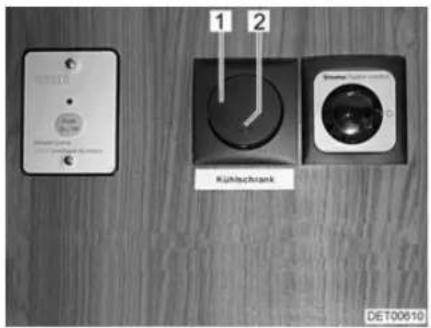
Fig. 139 Operating controls outside the refrigerator
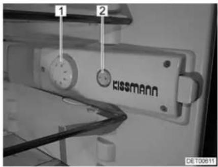
Fig. 140 Operating controls in the refrigerator
Switching on:
■ Open the panel above the conversion door.
■ Switch on the refrigerator with the switch (Fig. 139,1). The indicator lamp (Fig. 139,2) shows it is in operation.
■ Turn the temperature controller (Fig. 140,1) from position "0" to "1".
If the interior lighting is not on, switch the switch (Fig. 140,2) to the "I" position.
Switching off:
■ Switch off the refrigerator with the switch (Fig. 139,1). The indicator lamp (Fig. 139,2) goes out.
Adjust the temperature:
■ Set the temperature with the temperature controller (Fig. 140,1).
- Position "1" = lowest cooling power
- Position "7" = highest cooling power
Defrosting:
■ Switch off the refrigerator.
■ Switch off the interior lighting with the switch (Fig. 140,2).
■ Open the doors of the refrigerator and the freezer compartment and leave them open.
■ Mop up the defrosting water with a sponge or cloth.
■ Clean the unit (see chapter 12).
When frozen food is kept in the freezer compartment, temperatures of -18 °C or lower are reached in the freezer compartment even when the temperature controller is set to a low setting.
The refrigerator temperature depends on the ambient temperature (installation location), the frequency the door is opened with and the charging. If necessary, readjust the temperature controller.
▶ Further information can be obtained in the manufacturer's instruction manual.

10.6.4 Refrigerator door locking mechanism
The refrigerator has a separate freezer compartment. The specifications in this section correspondingly also apply to the door of the freezer compartment.

During the journey the refrigerator door must always be closed and locked in the closed position.

When the refrigerator is switched off, bring the refrigerator door into the ventilation position and lock it in place if possible. This prevents mould forming.
Depending on the model, it is possible to lock the refrigerator door in two positions:
- Closed refrigerator door during travel and when the refrigerator is in operation
- Slightly opened refrigerator door as a ventilation position when the refrigerator is switched off
Dometic 7 series with separate freezer compartment
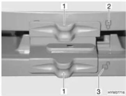
Fig. 141 Locking of the refrigerator door/freezer compartment door (Dometic 7 series with separate freezer compartment)
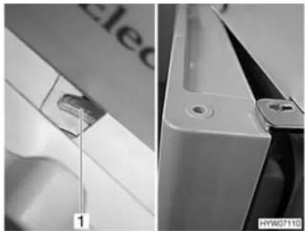
natural_image
Close-up of a white appliance with a handle and labeled component, showing front and side views (no readable text or symbols)Fig. 142 Refrigerator door/freezer compartment door in ventilation position (Dometic 7 series with separate freezer compartment)
Opening:
■ Push the lock (Fig. 141,1) to the side, so that the open lock "G" (Fig. 141,3) is completely visible.
■ Use recessed grip to open refrigerator door/freezer compartment door.
■ Fully close the refrigerator door/freezer compartment door.
■ Push the lock (Fig. 141,1) to the side, so that the closed lock "?" (Fig. 141,2) is completely visible.

Locking in the ventilation position:
■ Slightly open refrigerator door/freezer compartment door.
■ Push the lock completely to the right. The door latch (Fig. 142,1) keeps the refrigerator door/freezer compartment door in a fixed position. The refrigerator door/freezer compartment door will then stay slightly open (Fig. 142).
Kissmann with separate freezer compartment
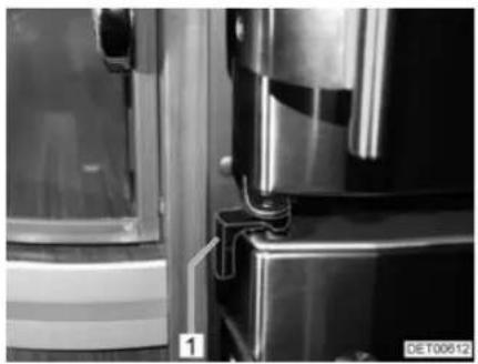
natural_image
Close-up of a metallic refrigerator with visible door and side panels, no text or symbols present.Fig. 143 Refrigerator door in operation position
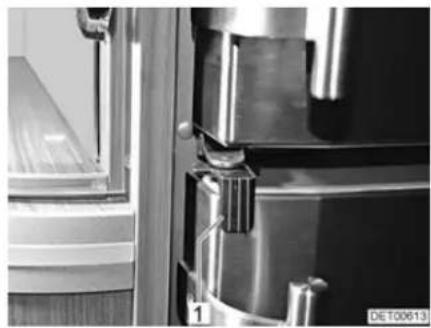
natural_image
Close-up of a metallic door with handle and clasp, showing internal components and a window (no visible text or symbols)Fig. 144 Refrigerator door locked
Opening:
■ Rotate lock (Fig. 143,1) towards the outside.
■ Open the refrigerator door at the handle.
Closing:
■ Fully close the refrigerator door.
■ Turn lock (Fig. 144,1) towards the centre of the refrigerator.

▷ Locking in the ventilation position is not possible.
Bringing into the ventilation position:
■ Open the refrigerator door.
■ Turn the lock inwards.
■ Close the refrigerator door. The refrigerator door will stay slightly open.
10.7 Air conditioning unit

The air conditioning unit only runs if the vehicle is connected to a 240 V power supply.
The external 240 V power supply must be protected by a fuse of at least 3 A. It is otherwise not possible to operate the air conditioning unit properly.
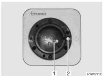
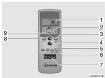
Fig. 145 Receiver Fig. 146 Remote control
The air conditioning unit is installed in the rear garage on the right behind a flap. The remote control (Fig. 146) for the air conditioning unit and the receiver (Fig. 145) is in the kitchen area.
To execute the individual switching commands, always point the remote control in the direction of the receiver.
Switching on:
■ Connect the vehicle to the 240 V power supply. The air conditioning unit is ready to operate.
■ Switch on the remote control with the switch (Fig. 146,7). The green indicator lamp (Fig. 145,1) indicates cooling mode.
■ Set the desired operating mode with the key (Fig. 146,8).
- "FAN": Only ventilation without cooling.
- "COMFORT": Cooling. The fan output and the room temperature can be set separately. The green indicator lamp in the receiver indicates the compressor is in operation and therefore cooling mode.
■ Set the desired fan output and room temperature with the keys (Fig. 146,3 and 4) if necessary. The arrow (Fig. 146,9) indicates the selected setting mode.
If the temperature set on the remote control is reached, the green indicator lamp goes out, the compressor is switched off and the circulation fan continues to run.

An additional key switch (Fig. 145,2) is on the receiver, which can be used to switch the air conditioning unit off or on without remote control. If the air conditioning unit is switched on by means of this key switch, the operating mode set last on the remote control is automatically selected.
Switching off:
■ To switch off, press the key (Fig. 146,7) on the remote control again.
Condensation accumulates on the vaporiser in cooling mode. To counteract any formation of germs, operate the air conditioning unit about 5 to 10 minutes in the "FAN" and "HIGH" positions to dry the vaporiser.

Timer The air conditioning unit can be switched on or off automatically from the current time up to 15 hours in advance with the integrated timer. Pre-programming up to a certain time is not possible.
■ To program, switch on the air conditioning unit with the key (Fig. 146,7) on the remote control.
■ Set the desired operating mode and room temperature with the keys (Fig. 146,8, 3 and 4).
■ Use the key (Fig. 146,5) to select the desired function (Fig. 146,1):
- "ON": Switching on
- "OFF": Switching off
■ Use the keys (Fig. 146,4) to select the desired switching time (1 to 15 hours). The arrow (Fig. 146,2) flashes and indicates the setting mode.
If "ON" (switch on) was selected, the air conditioning unit must be switched off again with the remote control after the setting process. The indicator lamp in the receiver flashes and confirms the programming.
■ The indicator lamp in the receiver flashes and confirms the programming if "OFF" (switch off) was selected. Do not switch off the air conditioning unit with the remote control.

To go easy on the batteries in the remote control, the infrared transmitter can be covered by hand and the remote control then switched off after the "OFF" programming. In this way no signal is transferred to the receiver and the programming is retained.
The key (Fig. 146,6) is used to send the settings of the remote control repeatedly to the receiver.
▶ Further information can be obtained in the manufacturer's instruction manual.
10.8 Dishwasher

▶ Repairs to the dishwasher may only be carried out be qualified personnel.
▶ Detergents for dishwashers are very corrosive. Therefore, never store detergents on the sink or within reach of children and never use for other purposes.
▶ Do not open the dishwasher door when the program is running or directly at the end of the program. Hot steam can escape.

▷ Use only dishwasher-proof crockery.
▷ Fill the salt container with special salt before the first washing cycle to protect the dishwasher against damage from chalk.
▶ Further information is available in the separate instruction manual "Dish-washer".

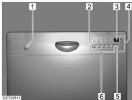
Fig. 147 Operating controls for the dishwasher
1 On/Off button
2 Button for setting the water softener
3 Multi-display
4 Display lamps and indicator lamps
5 Button for delayed start
6 Keys for program selection
The multi-display can show the following information:
- Set hardness level
- Set start time
● Remaining time of the washing program - Error code
The indicator lamps show when there is no salt or rinsing liquid.
Switching on:
■ Fill in detergent and rinsing liquid if necessary.
■ Close the door.
■ Press the "On/Off" button (Fig. 147,1). All program displays (Fig. 147,6) light up.
■ Press switch (Fig. 147,6) for desired program. All other program displays go out.
The three upper display lamps (Fig. 147,4) provide information about the program sequence:

Cleaning cycle in operation

Drying cycle in operation

Program cycle ended

Switching off:
Do not switch off the dishwasher until the display lamp "→" indicates the end of the program.

■ Press the "On/Off" button (Fig. 147,1).
■ Pull door lock upward and open the door.
If the vehicle is not going to be used for a long period or if it is not heated when there is a risk of frost, pump off all water from the dishwasher. This prevents deposits and frost damage.
Pumping out water:
■ Shut off the water supply to the dishwasher.
■ Switch on the dishwasher. The pump pumps the remaining water out of the pipes and the machine.
■ Switch off the dishwasher.
10.9 Central vacuum cleaner

▶ Do not suck up any sharp-edged or pointed objects such as needles, nails or razor blades. Risk of injury when changing the filter!
▶ Do not suck in any flammable or combustible liquids. Fire hazard!
▶ Do not allow children to play with the vacuum cleaner.
▶ Keep hair, loose clothing fingers and other parts of the body away from the intake openings.

Operate the vacuum cleaner only when a dust bag and all filters have been inserted.
Do not suck in any hot or smoldering objects such as cigarettes or hot ash.
Do not suck in any large objects such as paper tissues. These could block the hose.

The vacuum cleaner can get very hot during operation. If this happens, the motor switches itself off automatically. The vacuum cleaner is ready for use again after a cooling-down period of approx. 1 hour.
▶ Further information can be obtained in the manufacturer's instruction manual.
Connections In the vehicle there are two hose connections and an intake opening with a foot pedal.
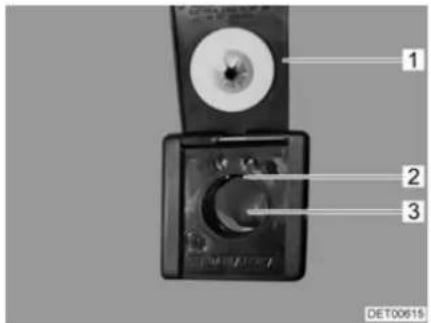
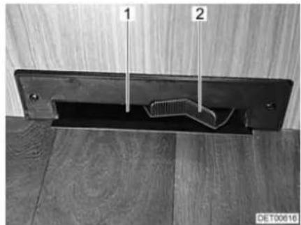
natural_image
Close-up of a metal bracket with two labeled parts (1 and 2) against a wooden surface, no text or symbols visible.Fig. 148 Hose connection Fig. 149 Intake opening with foot pedal
Operation The vacuum cleaner can be operated in various modes.
Connecting a hose:
■ Lift the flap (Fig. 148,1) on the hose connection.
■ Rotate the hose slightly and push it gently into the opening (Fig. 148,3).
As soon as the contacts on the end of the hose touch the contacts in the hose connection (Fig. 148,2), the vacuum cleaner starts up automatically.
Activating the intake opening:
■ Tilt the foot pedal (Fig. 149,2) to the right. The vacuum cleaner starts up.
■ Brush the dust in front of the intake opening (Fig. 149,1). The dust is sucked in.
Switching off the vacuum cleaner:
■ When the hose is connected: Rotate the hose slightly and pull it out of the connection.
■ When the intake opening is in operation: Tilt the foot pedal to the left.

▶ Only change the bag when the vacuum cleaner is switched off.
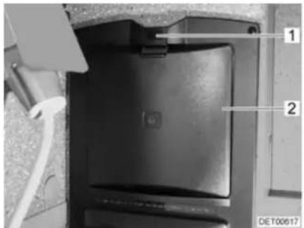
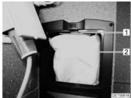
natural_image
Close-up of a mechanical component with labeled parts (1 and 2), no readable text or symbols beyond labelsFig. 150 Flap for dust bag Fig. 151 Dust bag
Changing the dust bag:
■ Press the unlocking device (Fig. 150,1) upwards.
■ Open the flap (Fig. 150,2).
■ Carefully pull the dust bag (Fig. 151,2) off the pipe tube (Fig. 151,1) and remove it.
■ Insert a new dust bag into the opening.
■ Attach the new dust bag onto the short tube. When doing this, first press the cardboard disk on the dust bag into the rear top corner and then pull the front part of the cardboard disk upwards.
■ Close flap. Lock must audibly lock into place.
Chapter overview
This chapter contains instructions regarding the sanitary fittings of the vehicle. The instructions address the following topics:
- water tank
- waste water tank
- complete water system
- toilet compartment
- toilet
11.1 Water supply, general

▶ Fill water tank from supply systems that have been verified to provide drinking water quality.
▶ Only use such hoses or containers when filling that have been approved for use with drinking water.
▶ Thoroughly rinse filling hose or container with drinking water before use (2 to 3 times capacity).
▶ Empty filling hose or container completely after use and close openings of the filling hose or container.
▶ Water left standing in the water tank or in the water pipes becomes undrinkable after a short period. Therefore, before each use of the vehicle, thoroughly clean the water pipes and the water tank. After each use of the vehicle completely empty the water tank and the water pipes.
In the case of lay-ups lasting more than a week disinfect the water system before using the vehicle.

If the vehicle is not used for several days or if it is not heated when there is a risk of frost, empty the entire water system. Leave the water taps on in central position. Leave the safety/drainage valve (if there is one) and all drain cocks open. Frost damage to appliances, frost damage to the vehicle and deposits in water-carrying components can be avoided in this way.
The water pump will overheat without water and can get damaged. Never operate water pump when the water tank is empty.
The vehicle is equipped with a fitted water tank. An electric water pump pumps the water to the individual water taps. Opening a water tap automatically switches on the water pump and pumps water to the tap.
The waste water tank collects the waste water. The water level in the water and waste water tanks can be checked on the panel.

Before using the water fittings, the 12 V power supply on the panel must be switched on. Otherwise the water pump will not work.
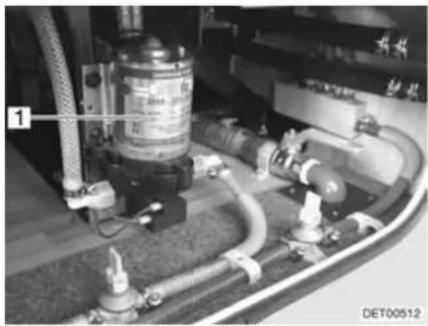
natural_image
Industrial piping and valve assembly with labeled component (no readable text or symbols)Fig. 152 Water pump
Position of the water pump
The water pump (Fig. 152,1) is mounted on the outside of the water tank.
11.2 Water tank
11.2.1 Drinking water filler neck with cap
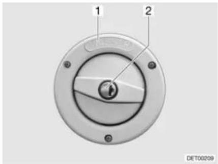
Fig. 153 Cap for the drinking water filler neck
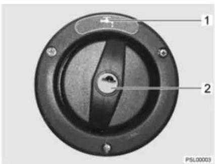
Fig. 154 Cap for the drinking water filler neck (alternative)
The drinking water filler neck is on the right or left side of the vehicle, depending on the model.
The drinking water filler neck is labelled by the word "WASSER" (water) (Fig. 153,1) or marked by the symbol "(Fig. 154,1). The cap is opened or closed using the key for the external flap locks.
Opening:
■ Insert key into locking cylinder (Fig. 153,2) and turn a quarter turn in an anticlockwise direction.
■ Remove cap.
■ Fill the water tank with drinking water.
Closing:
■ Place the cap on the drinking water filler neck.
■ Turn key one quarter turn in a clockwise direction.
■ Remove the key.
■ Check that the cap sits firmly on the drinking water filler neck.
11.2.2 Water drainage
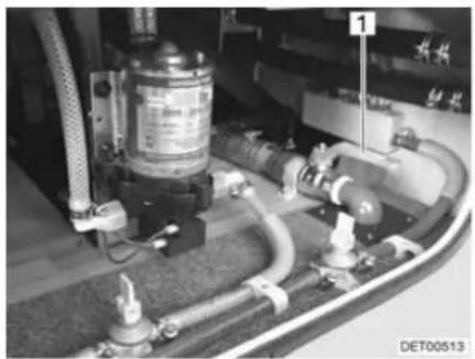
natural_image
Close-up of industrial piping and valves with no visible text or symbols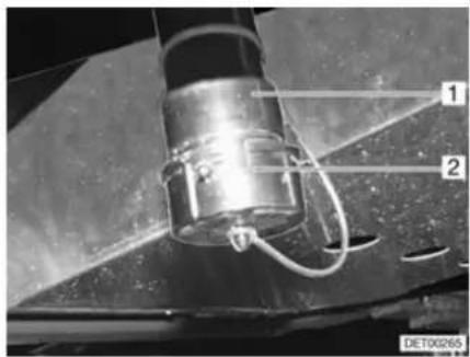
Fig. 155 Water tank drain cock Fig. 156 Water drain neck
Depending on the model, the drain cock (Fig. 155,1) is installed in the double floor on either the left or right side of the vehicle. The drain cock is labelled by the word "Wasser" (water).
A cap (Fig. 156,2) closes the water drain neck (Fig. 156,1).
A hose line can be connected to the water drain neck (Fig. 156,1).
11.2.3 Filling with water

When filling the water tank, observe the maximum permissible gross weight of the vehicle. Luggage must be reduced accordingly when the water tank is full.
To fill the water tank with drinking water, proceed as follows:
■ Open drinking water filler neck (Fig. 153).
- Fill the water tank with drinking water. Use a water hose, a water canister with a funnel or similar for filling.
■ Close drinking water filler neck.
11.2.4 Draining water
To empty the water tank, proceed as follows:
■ Unlock and remove the cap (Fig. 156,2) from the water drain neck (Fig. 156,1) by turning it a quarter turn in a clockwise direction.
■ Mount suitable hose to the water drain neck (Fig. 156,1) or place appropriate container under the water drain neck.
■ Open the external flap (see section 7.2).
■ Open drain cock. The water will drain.
■ Close drain cock.
■ Close the external flap.
■ Replace the cap and lock it by turning it a quarter turn in an anticlockwise direction.
11.3 Waste water tank

In case of frost add so much anti-freeze (such as kitchen salt) to the waste water tank so that the waste water cannot freeze.
▷ If the living area heater is out of order, the waste water tank no longer is sufficiently protected against frost.
▷ Never pour boiling water directly into the sink outlet. Boiling water could cause deformation and leaks in the waste water pipe system.

Only empty the waste water tank at disposal stations, camping sites or caravan sites especially provided for this purpose.
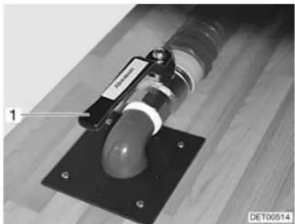
natural_image
Close-up of a mechanical device with a labeled component and mounting base (no readable text or symbols)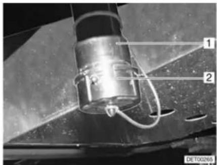
Fig. 157 Drain cock for waste water tank Fig. 158 Waste water drain neck
Depending on the model, the drain cock (Fig. 157,1) is installed in the double floor on either the left or right side of the vehicle. The drain cock can be accessed via the rear garage. The drain cock is labelled by the word "Abwasser" (waste water).
A cap (Fig. 158,2) closes the waste water drain neck (Fig. 158,1).
A hose line can be connected to the waste water drain neck (Fig. 158,1).
Emptying:
■ Unlock and remove the cap (Fig. 158,2) from the waste water drain neck (Fig. 158,1) by turning it a quarter turn in a clockwise direction.
■ Mount suitable hose to the waste water drain neck or place appropriate container under the waste water drain neck.
■ Open the external flap (see section 7.2).
■ Open drain cock (Fig. 157,1). The waste water will run out.
■ Close drain cock.
■ Close the external flap.
■ Replace the cap and lock it by turning it a quarter turn in an anticlockwise direction.
11.4 Odour seal
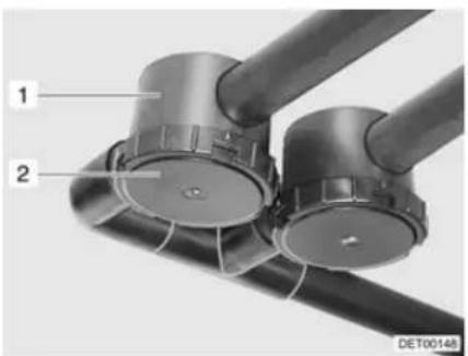
natural_image
Close-up of two black cylindrical mechanical components with labeled parts (1 and 2), no visible text or symbols beyond labels.Fig. 159 Odour seal
In order to prevent odours occurring in the waste water system, the vehicle - depending on the model - has been equipped with odour seals (Fig. 159,1). The odour seals are installed in the waste water pipes.
Clean the odour seals every two years at the latest. To do so, unscrew and remove the bottom cover (Fig. 159,2).
11.5 Filling the water system

When filling the water tank, observe the maximum permissible gross weight of the vehicle. Luggage must be reduced accordingly when the water tank is full.

The water pump will overheat without water and can get damaged. Never operate water pump when the water tank is empty.

The water system has several drain cocks (yellow) for emptying. The water quantity can be monitored on the panel while the water tank is filled.
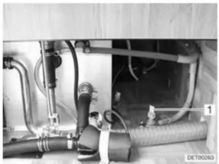
natural_image
Interior view of a mechanical or electrical assembly with hoses and pipes (no visible text or symbols)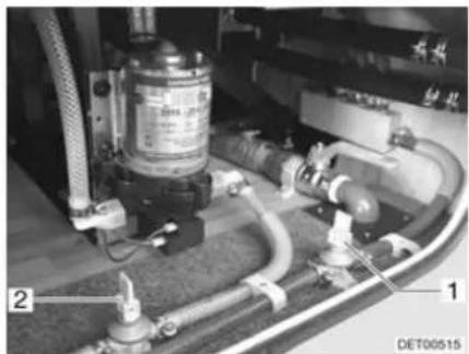
natural_image
Close-up of industrial piping and valves with no visible text or symbolsFig. 160 Drain cock on heater Fig. 161 Drain cock on water pump
■ Position the vehicle horizontally.
■ Switch on 12 V power supply on the panel.
■ Switch on water pump on panel.
■ Clean or disinfect water system.
■ Close all drain cocks (Fig. 160,1 and Fig. 161,1 and 2). To do this, set the rocking levers in a horizontal position.
■ Close all water taps.
■ Fill the water tank with drinking water.
■ Set all the water taps to "Hot" and open them. The water pump is turned on. The warm water pipes are filled with water.
- Keep the taps open until the water flowing out of the taps has no bubbles in it. This is the only way to ensure that the boiler is full of water.
■ Set all water taps to "Cold" and leave them open. This will fill the cold water pipes with water.
- Keep the taps open until the water flowing out of the taps has no bubbles in it.
■ Close all water taps.
11.6 Emptying the water system

If the vehicle is not used for several days or if it is not heated when there is a risk of frost, empty the entire water system. Leave the water taps on in central position. Leave the safety/drainage valve (if there is one) and all drain cocks open. Frost damage to appliances, frost damage to the vehicle and deposits in water-carrying components can be avoided in this way.
Always switch off the water pump on the panel when emptying the water system. Otherwise the water pump runs until it overheats or the battery is empty.
The water system has several drain cocks (yellow) for emptying.

To empty and ventilate the water system, proceed as follows. This prevents frost damage and deposits:
■ Position the vehicle horizontally.
■ Switch off water pump on panel.
■ Switch off the 12 V power supply on the panel.
■ Shut off the boiler (see section 10.4).
■ Open all drain cocks (Fig. 160,1 and Fig. 161,1 and 2). To do this, set the rocking lever in a vertical position.
■ Unscrew the cap of the water tank.
■ Remove the cap from the waste water drain neck and open the drain cock.
■ Open all water taps and set to the central position.
■ Hang the shower handset up in the shower position.
■ Check whether the water tank is completely empty.
■ Empty the waste water tank. Take note of the environmental tips in this chapter.
■ Empty Thetford cassette. Take note of the environmental tips in this chapter.
■ Clean the water tank and then rinse it out thoroughly.
■ Let the water system dry for as long as possible.
■ After emptying, leave all water taps on in the central position.
■ Leave all drain cocks open.
11.7 Toilet compartment

Do not transport any loads in the shower tray. The shower tray or other items of equipment in the toilet compartment can be damaged.

For ventilation purposes during or after a shower, and for drying wet clothing, close the toilet compartment door and open the window or the toilet compartment skylight. This improves the air circulation.
▷ Close the shower curtain completely when showering, so that no water is able to enter the area between the wash room wall and the shower tray.
After taking a shower, rinse soap residue from the shower tray, otherwise cracks can appear in the shower tray over time.
▶ After using the shower, wipe it dry to prevent moisture from collecting.
▶ Further information about cleaning the toilet compartment can be found in the section 12.2.
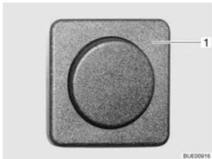
natural_image
Close-up of a circular button component with a textured square border and a numbered label '1' pointing to it (no text or symbols on the button itself)Fig. 162 Light switch
The switches for the toilet compartment lighting are installed in different places in the toilet compartment depending on the model.
For example, the light switch (Fig. 162,1) of the toilet compartment is located under the bathroom cabinet.
11.8 Toilet

▷ If there is any risk of frost and the vehicle is not heated, empty the sewage tank (cassette).
Do not sit on the lid of the toilet. The lid is not designed to bear the weight of a person and could break.
Use a suitable chemical for this toilet. The ventilation will merely remove the odour but not germs and gases. Germs and gases will have a detrimental effect on the sealing rubbers.

▶ Further information can be obtained in the manufacturer's instruction manual.

Only empty the sewage tank (cassette) at disposal stations, at camping sites or caravan sites, that are especially provided for this purpose.
11.8.1 Swivel toilet
The flushing of the Thetford toilet is fed directly from the water system of the vehicle. The toilet bowl can be moved into the optimal position.
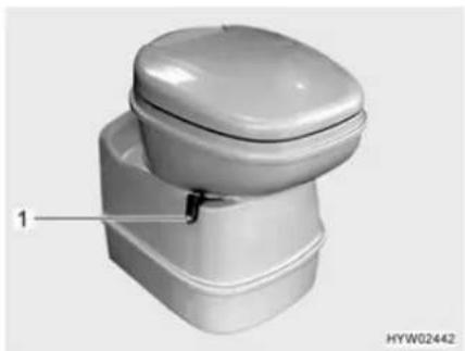
natural_image
3D rendering of a white toilet with lid and base, labeled with number 1 (no text or symbols on the toilet itself)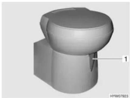
natural_image
3D rendered mechanical component with a curved top and base, labeled with number 1 (no text or symbols on the object itself)Fig. 163 Thetford toilet bowl, swivelling Fig. 164 Thetford toilet bowl, swivelling (alternative)
The operating unit is located close to the toilet bowl.
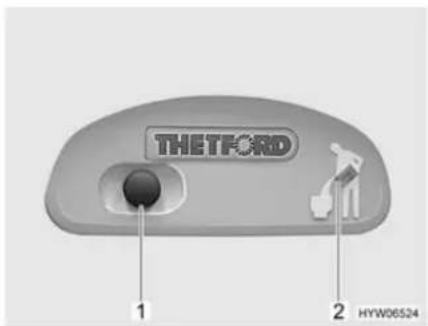
Fig. 165 Flush button/indicator lamp Thetford toilet
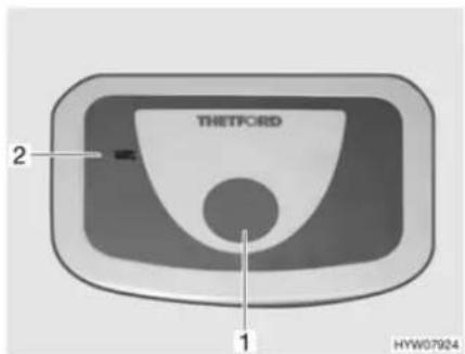
Fig. 166 Flush button/indicator lamp Thetford toilet (alternative)
Flushing:
■ Before flushing open the sliding trap of the Thetford toilet. To do this, push the slide lever (Fig. 163,1 or Fig. 164,1) in an anticlockwise direction.
■ For flushing, press the blue flush button (Fig. 165,1 or Fig. 166,1).
■ After flushing close the sliding trap. To do this push the slide lever in a clockwise direction.
The indicator lamp (Fig. 165,2 or Fig. 166,2) goes on whenever the Thetford cassette has to be emptied.
Emptying:
■ Turn the slide lever (Fig. 163,1 or Fig. 164,1) in a clockwise direction. The sliding trap is closed. To empty, the sliding trap in the Thetford toilet must be closed.
■ Remove the Thetford cassette and empty it as described in sections 11.8.3 and 11.8.4.
11.8.2 Vacuum toilet (Dometic)
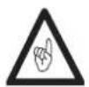
▶ Only flush the toilet if the toilet lid is closed.
The flushing of the toilet is fed directly from the water system of the vehicle.
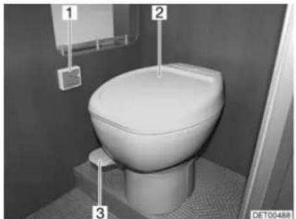
natural_image
Interior view of a white toilet in a bathroom with numbered labels (1, 2, 3) and no visible text or symbols on the toilet itself.
Fig. 167 Vacuum toilet Fig. 168 Vacuum toilet panel
Putting into operation:
■ Turn on power supply. The yellow LED (Fig. 168,1) on the panel (Fig. 167,1) turns on for ca. 1 minute. A vacuum is generated in the system.
If the green LED (Fig. 168,3) on the panel lights up, lift the pedal (Fig. 167,3) briefly, so that some water runs into the toilet bowl (Fig. 167,2) and the stopper on the bottom is covered with water.
The vacuum toilet is ready for operation.

Flushing only functions if the green LED is lit.
Flushing:
■ Close the lid of the toilet.
■ Press down the pedal (Fig. 167,3) for several seconds.
■ Briefly lift the pedal, so that some water runs into the toilet bowl (Fig. 167,2) and the stopper on the bottom is covered with water.
The red LED (Fig. 168,2) lights up if the cassette must be emptied or removed.
Removing the cassette:
■ Remove the cassette and empty it as described in sections 11.8.3 and 11.8.4.
11.8.3 Removing the cassette

The sewage tank (cassette) can only be taken out if the sliding trap is closed.
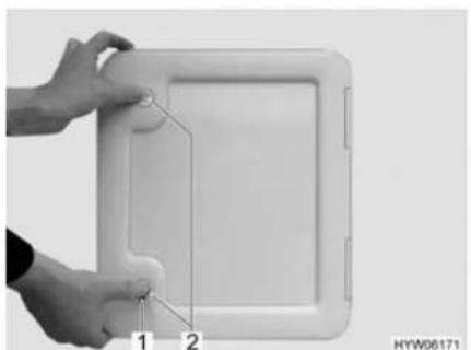
natural_image
Close-up of hands holding a white rectangular device with a small attached component, labeled 1 and 2 (no text or symbols on the device itself)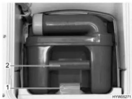
natural_image
Interior view of a mechanical device showing internal components and labeled parts (no readable text or symbols)Fig. 169 Flap for the toilet cassette Fig. 170 Thetford cassette
■ Open the flap for the cassette on the outside of the vehicle. Insert the key into the locking cylinder of the push-button lock (Fig. 169,1) and turn a quarter turn.
■ Remove the key.
■ Press both push-button locks (Fig. 169,2) simultaneously with your thumb and open the flap for the cassette.
■ Press the release (Fig. 170,1) and pull out the toilet cassette on the handle (Fig. 170,2).
11.8.4 Emptying the cassette
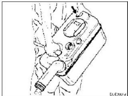
natural_image
Line drawing of a mechanical component with no visible text or symbolsFig. 171 Emptying the Thetford cassette
■ Take the cassette to a disposal point especially provided for this purpose. As you do this, point the drainage neck upwards.
■ If possible, turn the drainage neck upwards.
■ Remove the cap of the drainage neck.
■ Point the cassette with the drainage neck downwards.
■ For Thetford cassettes: Activate the aeration knob with your thumb. The cassette empties.
■ Close drainage neck with the cap.
■ If the drainage neck has been turned upwards: Return the drainage neck to its original position.
■ Push the cassette back to its original position.
■ Ensure that the cassette is secured by the retaining clip.
■ Lock the flap for the cassette.
Chapter overview
This chapter contains instructions regarding the care of the vehicle.
The instructions address the following topics:
• exterior of the vehicle
- interior
- water system
- extractor hood
- toilets
- winter operation
At the end of the chapter there is a checklist of measures you must carry out if you are not going to use the vehicle for an extended period of time.
The checklist address the following topics:
- temporary lay-up
- winter lay-up
- start-up after a lay-up
12.1 External care
12.1.1 Washing with a high-pressure cleaner

Do not clean the tyres with a high-pressure cleaner. The tyres might be damaged.
Do not spray external applications (deco-films) directly with the high-pressure cleaner. The external applications could come off.
Before cleaning the vehicle with a high-pressure cleaner, observe the operating instructions of the high-pressure cleaner.
When cleaning with the nozzle for circular jet between the vehicle and the cleaning nozzle, maintain a minimum distance of approx. 700 mm.
Take into consideration that the jet of water comes out of the cleaning nozzle with pressure. The vehicle may be damaged by incorrect handling of the high-pressure cleaner. The temperature of the water should not be above 60 °C.
Keep the jet of water in constant movement during the washing process. Do not direct the water jet at clearances, built-in electrical parts, plugs, seals, the ventilation grill or the skylights. The vehicle may be damaged or water may enter the interior.
12.1.2 Washing the vehicle

▷ Never clean the vehicle in the car wash. Water can enter the refrigerator grills, the waste gas vents, the ventilation of the extractor hoods or the forced ventilations. The vehicle could be damaged.
■ Wash the vehicle only on a washing site intended for this purpose. Avoid full sunshine. Observe environmental measures.
■ Only clean external applications and synthetic parts with plenty of warm water, dish washing liquid and soft cloth.
■ Wash down the vehicle with plenty of water, a clean sponge or a soft brush. In the case of stubborn dirt add dish washing liquid to the water.
■ Painted exterior walls may also be cleaned with a caravan cleaner.
■ Add-on parts made of glass-fibre reinforced plastic (GRP) require a regular follow-up treatment with a polisher. This way these parts will not turn yellow and the sealing of the surface remains intact.
■ Treat rubber seals of doors and storage flaps with talc.
■ Treat locking cylinder of doors and storage flaps with graphite dust.
12.1.3 Windows of acrylic glass

Acrylic glass windows are delicate and require very careful handling.
▷ Never rub acrylic glass windows dry as dust particles might damage the surface!
▶ Only clean acrylic glass windows with plenty of warm water, some dish washing liquid and a soft cloth.
▷ Never use glass cleaning agents with chemical, abrasive or alcohol-containing additives. Premature brittleness of the panes and associated cracks may result from their use.
Avoid contact of cleansing agents used for the body (e.g. tar- or silicone-removing agents) with acrylic glass.
Do not clean vehicle in car wash.
Do not attach stickers to the acrylic glass windows.
▶ Having cleaned the vehicle rinse acrylic glass with sufficient clear water.
▷ Treat rubber seals with glycerin.

An acrylic glass cleanser with antistatic effect is suitable for a follow-up treatment. Small scratches can be treated with an acrylic glass polish. These agents are available at the accessories shop.
12.1.4 Underbody
The underbody of the vehicle is partly coated with an age-resistant underbody protection. Should the underbody protection be damaged, repair immediately. Do not treat areas coated with underbody protection with spray oil.

Only use products approved by the manufacturer. Our authorised dealers and service centres will be happy to advise you.
12.1.5 Waste water tank
Clean the waste water tank after every use of the vehicle.
Cleaning:
■ Empty the waste water tank.
■ Thoroughly rinse out the waste water tank with fresh water.
■ If possible, clean waste water sensors through the cleaning opening by hand.
12.1.6 Entrance step
If the entrance step is lubricated, coarse particles of dirt can settle on the lubricant during the journey and cause damage to the operating mechanism of the entrance step. Therefore, do not lubricate the moving parts of the entrance step.
12.1.7 Driver's cabin insulation mat (model I)
Clean the insulation mat for the driver's cabin with clear, lukewarm water. Remove heavier soiling with a cloth and some white spirits. Afterwards, immediately rinse the cleaned area with lukewarm water.
12.1.8 Electrical-hydraulic steady legs
Cleaning:
■ Clean the steady legs regularly. Dirt and other contamination can impair its functioning.
Spraying:
If the steady legs are to remain extended for any length of time, spray silicone spray onto the lifting cylinder once per week. In a salty environment, reduce that interval to two or three days.
■ Spray the outside of the entire steady legs with an anti-rust agent (e.g. Tectyl) once annually. This protects the steady legs against corrosion and rust.
12.2 Interior care

▷ If possible, treat stains immediately.
Acrylic glass windows are delicate and require very careful handling (see section 12.1.3).
▷ Synthetic parts in the toilet and living area are very delicate and should be treated with care. Do not use solvents, alcohol-containing cleansers or scourers containing sand. This procedure will help you to avoid brittleness and formation of cracks.
Do not pour any corrosive agents into the drain holes. Never pour boiling water directly into the drain holes. Corrosive agents and boiling water cause damage to drainage pipes and siphon traps.
Do not use vinegar based products to clean the toilet and water system, or for decalcification of the water system. Vinegar-based products may cause damage to seals or parts of the installation. Use standard decalcifying products for decalcification.
▷ Save water. Mop up all remaining water.
▷ Vacuum off carpets and cushions with a suitable brush attachment.
For information about the use of maintenance products, our representatives and service centres will be glad to advise.

■ Surface and knobs of furniture, lamps and synthetic parts in the toilet and living area should be cleaned with water and a wool cloth. A mild cleanser may be added to the water. If required, use furniture polish for the painted surfaces.
■ Clean upholstery with dry foam specially manufactured for the use on upholstery or with the foam of a mild detergent. Do not wash upholstery. Always have it cleaned. Protect upholstery from direct sunlight so that it does not lose its colour.
■ Clean the imitation leather coverings by wiping them off in circular motion with a soft cloth or sponge and a mixture of lukewarm water and mild lather. Treat stubborn stains with a soft brush. For very hard-to-remove stains, use a mixture of alcohol and water mixed in a 1:1 ratio. Afterwards, wipe it off with soap water. Do not use any products that contain solvents or abrasives.
■ Wipe off Teflon coverings with an absorbent cloth or sponge and use a mild household detergent.
Never rub wet or oily stains. Instead, dab them with an absorbent cloth. Work from the outside to the inside to prevent spreading the stain.
When treating solid or dried stains, always try to scrape them off with a dull knife or scraper or remove them off with a soft brush. Afterwards, dab off any residue with a moist cloth.
■ Curtains and net curtains should be dry cleaned.
■ Vacuum clean the carpet, if necessary clean with carpet shampoo.
■ Clean PVC-floor covering with a mild, soapy cleanser for PVC floors. Do not place carpet on wet PVC-floor covering. The carpet and the PVC-floor covering may stick together.
■ Never clean the sink or the gas cooker with a scourer. Avoid anything which may cause scratching or grooves.
■ Clean gas cooker only with a moist cloth. Prevent any water from penetrating the gas cooker. Water may damage the gas cooker.
■ Brush insect screens on doors, windows and skylights with a soft brush or vacuum with the brush attachment of the vacuum cleaner.
■ Brush blinds with a soft brush or vacuum with the brush attachment of the vacuum cleaner. Grease or stubborn dirt may be removed with a mild soap at 30 °C (curd soap).
■ Brush Roman shades with a soft brush or vacuum with the brush attachment of the vacuum cleaner. Grease or stubborn dirt may be removed with a mild soap at 30 °C (curd soap).
■ Unrolled seat belts can be cleaned with warm soapsuds. The seat belt must be completely dry before being rolled up.
12.3 Water system
12.3.1 Cleaning the water tank
■ Empty the water tank and close the drainage opening.
■ Remove the cap of the water tank.
■ Fill water tank with water and some washing-up liquid (do not use any scourers).
■ Using a trade standard brush for washing dishes, scrub the water tank until there is no longer any visible deposit.
■ Scrub also the pump housing.
■ If possible, clean fresh water sensors through the cleaning openings by hand
■ Rinse water tank with copious amounts of drinking water.
12.3.2 Cleaning the water pipes

▶ Only use suitable cleaning agents as sold by the specialist trade.

▷ Collect any emerging mixture of water and cleaning agent for correct disposal.
■ Empty the water system.
■ Close all drain holes and drain cocks.
■ Fill mixture of water and cleaning agent into the water tank. Observe the manufacturer's instructions regarding the mixing ratio.
■ Open the drain cocks one by one.
■ Leave the drain cocks open until the mixture of water and cleaning agent has reached the respective drain.
■ Close the drain cocks.
■ Set all the water taps to "Hot" and open them.
■ Leave the water taps open until the mixture of water and cleaning agent has reached the drain.
■ Set all water taps to "Cold" and open them.
■ Leave the water taps open until the mixture of water and cleaning agent has reached the drain.
■ Close all water taps.
■ Flush the toilet several times.
- Allow the cleaning agent to act in accordance with the manufacturer's instructions.
■ Empty the water system. Collect the mixture of water and cleaning agent for correct disposal.
■ For rinsing fill the entire water system with drinking water and empty again several times over.
12.3.3 Disinfecting the water system

▶ Only use suitable disinfectants as sold by the specialist trade.

▷ Collect any emerging mixture of water and disinfectant for correct disposal.
■ Empty the water system.
■ Close all drain holes and drain cocks.
- Fill mixture of water and disinfectant into the water tank. Observe the manufacturer's instructions regarding the mixing ratio.
■ Open the drain cocks one by one.
■ Leave the drain cocks open until the mixture of water and disinfectant has reached the respective drain.
■ Close the drain cocks.
■ Set all the water taps to "Hot" and open them.
■ Leave the water taps open until the mixture of water and disinfectant has reached the drain.
■ Set all water taps to "Cold" and open them.
■ Leave the water taps open until the mixture of water and disinfectant has reached the drain.
■ Close all water taps.
■ Flush the toilet several times.
■ Allow the disinfectant to act in accordance with the manufacturer's instructions.
■ Empty the water system. Collect the mixture of water and disinfectant for correct disposal.
■ For rinsing fill the entire water system with drinking water and empty again several times over.
12.4 Extractor hood

▶ Prior to carrying out work on the device, turn off the power supply.
Clean the extractor hood filter occasionally. How often cleaning is necessary depends on how often the extractor hood is used. Do not wait to clean the filter until the performance of the extractor hood has noticeably decreased.
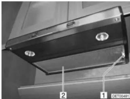
Fig. 172 Extractor hood
Cleaning the filter:
■ Pull down the filter (Fig. 172,2) with the handle (Fig. 172,1).
■ Wash the filter with warm water and some washing-up liquid.
■ Let the filter dry completely and re-install.
12.5 Vacuum toilet (Dometic)
If the toilet will not be used for a longer period of time, for example for Winter lay up, the toilet must be cleaned and completely emptied.
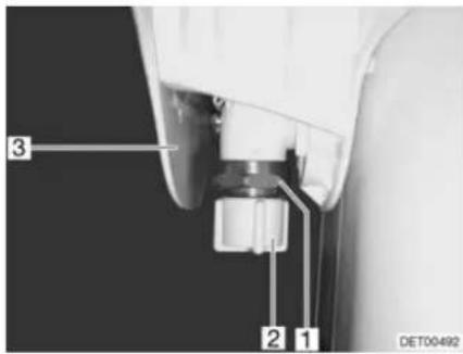
Fig. 173 Vacuum toilet valve
Emptying valve:
Empty the entire water system.
■ Press the toilet pedal several times, until no more water flows.
■ Empty the cassette at a disposal station authorized for this purpose and clean it.
■ Turn off power supply.
■ Remove cover (Fig. 173,3).
■ Unscrew the cap (Fig. 173,2).
■ Place a suitable container under the valve (Fig. 173,1).
■ Press the pedal several times until water no longer comes out of the valve.
■ Screw the cap back on and attach cover.
12.6 Winter care
De-icing salt damages the underbody and the parts open to water spray. We recommend that you wash the vehicle more frequently during wintertime. Mechanical and surface treated parts and the underside are under particular strain, and should therefore be cleaned thoroughly.

If there is any risk of frost, always run heater at a minimum of 15^ C. Switch the circulation fan (if there is one) to automatic. In the case of extreme external temperatures, the furniture flaps and doors should be left slightly open. The inflowing warm air can help prevent the freezing of water pipes, for example, and counteract the formation of condensation in the storage spaces.
If there is any risk of frost, cover the outside surface of the windows with winter insulation mats.
12.6.1 Preparations
■ Check the vehicle for paint and rust damage. Repair damage as necessary.
■ Make certain that water cannot penetrate the automatic floor ventilation system and the heater.
■ Use a wax-based rust inhibitor to protect the metal parts of the underbody.
■ Use appropriate protection for external painted surfaces.
12.6.2 Winter operation
During winter operation, condensation develops when the vehicle is occupied under low-temperature conditions. To ensure good interior air quality and avoid vehicle damage from condensation, sufficient ventilation is essential.
■ When heating the vehicle, the heater should be at the highest setting and roof storage cabinets, curtains and blinds should be opened. This ensures optimal ventilation.
In the morning, lift up all cushions, air out storage boxes and dry any damp areas.
▷ If condensation has still developed, just wipe it off.

12.6.3 At the end of the winter season
■ Thoroughly clean the underbody of the vehicle and the engine. When this is done, corrosion-inducing anti-freeze agents (salts, alkaline residues) are removed.
■ Clean the exterior and use regular car wax to protect metal surfaces.
12.7 Lay-up
12.7.1 Temporary lay-up

If the vehicle has been stationary for a long period (approx. 10 months) have the braking and gas systems checked by an authorised specialist workshop.
▶ Take into consideration that water is undrinkable after only a short time.
▶ Animal damage to cables can lead to short circuits. Fire hazard!
Animals (especially mice) can cause great damage to the interior of the vehicle. This is especially true if the animal remains undisturbed in a parked vehicle.
The animals can get into the vehicle at an opportune moment and hide from view.
To keep damages from animals to a minimum or to avoid them altogether, regularly check the vehicle for damage or animal traces. This is especially important approx. 24 hours after parking the car in storage.
If animal traces are found, contact your authorised dealer or service centre. If damage to cables has occurred, they can result in short circuits. The vehicle could catch fire.
Before laying up the vehicle, go through the following checklist:
Base vehicle
| Activities Done | |
| Completely fill fuel tank. This prevents corrosion damage within the fuel tank system | |
| Jack up vehicle so that the wheels do not bear any load, or move vehicle every 4 weeks. This prevents any pressure points from occurring on tyres and wheel bearings | |
| Protect the tyres from direct exposure to the sun. Danger of formation of cracks! | |
| Inflate tyres up to the recommended maximum pressure | |
| Always provide for sufficient ventilation in the underbody area | |
| ▷ Humidity or lack of oxygen e.g. by covering with plastic film may cause optical irregularities to the underbody. | |
| In addition observe the notes in the operating manual of the base vehicle |
Body
| All vents should be sealed with the appropriate caps and all other openings (apart from forced ventilations) should also be sealed. This prevents animals (e.g. mice) from gaining entry | |
| Air the interior, all storage compartments accessible from the outside, and the parking space (e.g. garage) every 3 weeks in order to prevent the occurrence of condensation and resulting mould formation |
Interior
| Place upholstery in an upright position for ventilation, and cover | |
| Clean refrigerator | |
| Allow refrigerator and freezer compartment doors to remain slightly open | |
| Search for traces of animals that have gained entry | |
| Disconnect the flat screen from the mains and, if necessary, remove it from the vehicle |
Gas system
| Close regulator tap on the gas bottle | |
| Close all gas isolator taps | |
| Always remove gas bottles from the gas bottle compartment, even if they are empty |
Electrical system
| Fully charge living area and starter battery Charge the battery for at least 20 hours before laying up. | |
| Disconnect the living area battery from the 12 V power supply on the panel |
Water system
| Empty the entire water system. Blow out the residual water from the water pipes (0.5 bar max.). Leave the water taps on in central position. Leave the safety/drainage valve (if there is one) and all drain cocks open. Observe the notes in chapter 11 |
12.7.2 Winter lay-up
Additional measures are required if laying up the vehicle over winter:
Base vehicle
| Activities Done | |
| Clean body and underbody thoroughly and spray with hot wax or protect with varnish | |
| Fill fuel tank with winter diesel | |
| Check antifreeze in the cooling water | |
| Rectify damage to the paintwork |
Body
| Keep the forced ventilation open | |
| Clean and lubricate the mounted steady legs | |
| Clean and grease all door and flap hinges | |
| Brush oil or glycerine on all locking mechanisms | |
| Rub all rubber seals with talc | |
| Use graphite dust to treat locking cylinders |
Interior
| Position de-humidifiers | |
| Remove upholstery from the vehicle and store in a dry place | |
| Air the interior every 3 weeks | |
| Empty all cabinets and storage compartments, open flaps, doors and drawers | |
| Thoroughly clean the interior | |
| If there is a risk of frost, do not leave the flat screen in the vehicle |
Electrical system
| Remove starter and living area batteries and store in a place protected from frost (see chapter 9) |
Water system
| Clean the water system using a cleaning agent from a specialised store |
Complete vehicle
| Arrange the tarpaulins in such a way that the ventilation openings are not covered, or use porous tarpaulins |
12.7.3 Starting up the vehicle after a temporary lay-up or after lay-up over winter
Go through the following checklist before start-up:
| Base vehicle | Activities Done | |
| Check the tyre pressure on all tyres | ||
| Check the tyre pressure of the spare wheel |
| Body | Clean the pivot bearing of the entrance step | |
| Check the functioning of the fitted steady legs | ||
| Check that the doors, windows and skylights are working properly | ||
| Check the function of all external locks | ||
| Remove the cover from the waste gas vent of the heater (if there is one) | ||
| Remove the winter cover from the refrigerator grills (if there is one) |
| Gas system | Put the gas bottles in the gas bottle compartment, tie down and connect to the gas pressure regulator |
| Electrical system | Connect to 240 V power supply using the external socket | |
| Fully charge living area and starter battery | ||
| Charge the battery for at least 20 hours after lay-up. | ||
| Connect the living area battery with the 12 V power supply via the panel | ||
| Check that the electrical system are working, e.g. interior light, socket and all installed electrical appliances |
| Water system | Disinfect water pipes and water tank | |
| Check the functionality of the operating lever for the waste water tank | ||
| Close all drain cocks and water taps | ||
| Check the water taps, drain cocks and water distributors for leaks |
| Appliances | Check the function of the refrigerator | |
| Change heating fluid of the hot-water heater every 2 years | ||
| Check the function of the heater/boiler | ||
| Check the function of the gas cooker | ||
| Check the function of the air conditioning unit |
Chapter overview
This chapter contains instructions about inspection and maintenance work concerning the vehicle.
The maintenance instructions address the following topics:
• electrical-hydraulic steady legs
• Alde hot-water heater
• independent vehicle heater
• air conditioning unit
• vacuum cleaner
● replacing bulbs and fluorescent tubes
At the end of the chapter you will find important instructions on how to obtain spare parts.
13.1 Inspection work
Like any technical appliance, the vehicle must be inspected at regular intervals.
This inspection work must be carried out by qualified personnel.
Special technical knowledge, which cannot be taught within the framework of this instruction manual, is required for these tasks. Personnel with this technical knowledge are available for assistance at all authorised dealers and service centres. Their experience and regular technical instruction by the factory as well as equipment and tools guarantee expert and up-to-date inspection of the vehicle.
The service centre in charge will confirm the work performed.
Have chassis inspections confirmed in the chassis manufacturer's customer service booklet.

Observe the inspections indicated by the manufacturer and have them carried out at the specified intervals. The value of the vehicle is thus preserved.
The confirmation of the inspection work carried out serves as valid proof in the event of damage and guarantee claims.
13.2 Maintenance work
As with every machine, this vehicle requires maintenance. The extent and frequency of the maintenance work required depend on conditions of operation and use. More difficult operating conditions make it necessary to service the vehicle more often.
Have the base vehicle and the appliances serviced at the intervals specified in the corresponding instruction manuals.
13.3 Electrical-hydraulic steady legs

Have the oil changed every 3 years by your authorised dealer or the service centre.
If oil needs to be topped up, use only oils specified by the manufacturer. Refer to the manufacturer's separate instruction manual for information, or ask your authorised dealer or the service centre.
Check the system's oil level at least once per month with the steady legs fully retracted.
The filling level must be approximately two to four centimetres below the filler opening.
13.4 Alde hot-water heater

▷ Check the level of the heating fluid regularly on the compensator reservoir.
During or after the first operating hours of the hot-water heater, the filling level may fall below the minimum mark. If this is the case, top up the heating fluid.
We recommend to bleed the heating system after the initial heater operation and to check the glycol content.
Have heating fluid changed by an authorised dealer or a service centre at intervals of approximately two years as corrosion-protection wears off after some time.
Top up heating system with a water-glycol mixture (60 : 40) only. This mixture offers frost protection up to approx. -25 °C. When topping up hot-water heaters that are connected to the engine's cooling circuit, please observe the instructions in the instruction manuals of the manufacturers.

▶ Further information can be obtained in the manufacturer's instruction manual.
13.4.1 Checking the fluid level
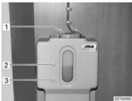
Fig. 174 Compensator reservoir hot-water heater
■ Switch off the hot-water heater and allow it to cool down.
■ Check if the fluid level is between the marks "MIN" (Fig. 174,3) and "MAX" (Fig. 174,2) on the compensator reservoir (Fig. 174).
13.4.2 Topping up heating fluid
■ Position the vehicle horizontally. This prevents the formation of bubbles.
■ Switch off the hot-water heater and allow it to cool down.
■ Unscrew or pull off the panel.
■ Open the rotary lid (Fig. 174,1) on the compensator reservoir.
■ Slowly remove cover with circulating pump upwards.
- Check anti-freeze with an anti-freeze hydrometer. The frost protection content must be 40 % or correspond to a frost protection of -25 °C.
■ Fill water frost protection mixture slowly into the compensator reservoir.
The optimum fluid level is reached when the fluid in the compensator reservoir is 1 cm above the "MIN" mark.

13.4.3 Bleeding the heating system
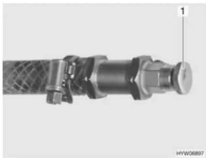
natural_image
Close-up of a mechanical pipe fitting with a textured central component and a labeled pin (1), no visible text or symbols beyond the number.Fig. 175 Bleeding valve of hot-water heater
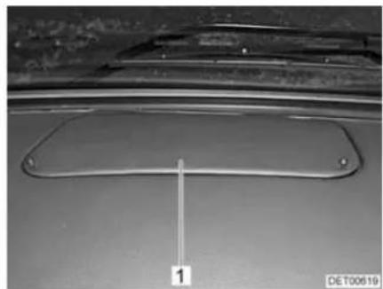
natural_image
Close-up of a metallic mechanical component with a labeled dimension line (1), no readable text or symbols present.Fig. 176 Cover in the dashboard
The bleeding valves are built in nearby the radiators. Depending on the model, the bleeding valve may be concealed under a cover (Fig. 176,1) in the dashboard.
■ Switch off the hot-water heater and allow it to cool down.
■ Open bleeding valve (Fig. 175,1) and leave open until no more air escapes.
■ Close bleeding valve.
■ Repeat this procedure at all bleeding valves.
■ Check to see if the hot-water heater warms up.
13.5 Independent vehicle heater
Use the independent vehicle heater for 10 minutes at least once a month with a cold engine and smallest fan settings.
Before the heating season starts, have the independent vehicle heater checked by an authorised specialist workshop.
13.6 Air conditioning unit (Truma)

▶ Prior to carrying out work on the device, turn off the power supply.

▷ Never operate the air conditioning unit without a lint filter. Without a lint filter, the vaporiser becomes dirty and the capacity of the air conditioning unit is consequently impaired.
Condensation can enter the vehicle if the condensation drain is clogged up. Keep the condensation drain free from dirt, leaves and similar.
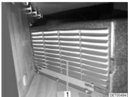
natural_image
Interior view of a room with horizontal slatted panels and metal fixtures (no visible text or symbols)Fig. 177 Air conditioning unit
The air conditioning unit is installed in the double floor on the right side of the vehicle. The lint filter can be accessed via a flap in the rear garage.
A lint filter (Fig. 177,1) for the air circulation suction system is at the front of the air conditioning unit. The lint filter must be cleaned at regular intervals, at least twice a year however, and replaced if necessary.
The condensation drain is under the floor of the vehicle. Keep the drain hose free from dirt, leaves or similar to allow the condensation to be drained.
13.7 Central vacuum cleaner

▶ Prior to carrying out work on the device, turn off the power supply.

▷ Never operate the vacuum cleaner without a filter. Dirt can enter the motor and impair its performance.
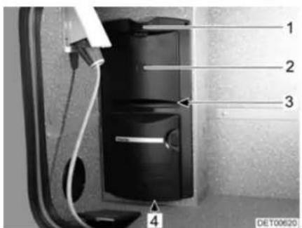
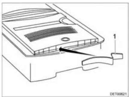
natural_image
Technical line drawing of a device component with a labeled arrow pointing to a feature (no text or symbols present)Fig. 178 Vacuum cleaner Fig. 179 Blow-out filter
Changing the motor filter:
■ Press the unlocking device (Fig. 178,1) upwards.
■ Open the flap (Fig. 178,2).
■ Carefully remove the dust bag.
■ Reach into the vacuum cleaner and pull out the motor filter (Fig. 178,3).
Changing the blow-out filter:
■ Insert a new motor filter or wash out the motor filter manually, allow it to dry and put it back in.
■ Align the motor filter. The sides of the motor filter must be underneath the vertical ribs all round.
■ Insert the dust bag.
■ Close flap.
■ Reach into the centre of the blow-out opening (Fig. 178,4).
■ Pull out the blow-out filter (Fig. 179,1).
■ Push the new blow-out filter outwards to the left from the centre, and then push it to the right (Fig. 179).
13.8 Replacing bulbs and fluorescent tubes

▶ Bulbs and light fittings can be extremely hot. Therefore, allow lights to cool down before changing bulbs.
▶ Shut off the power supply on the safety cut-out in the 240 V fuse box before changing bulbs.
▶ Store bulbs in a safe place inaccessible to children.
▶ Do not use any bulb that has been dropped or which shows scratches in its glass. The bulb might burst.
▶ Lights can get very hot. When the light is switched on, there must always be a safety distance of 30 cm between light and flammable objects. Fire hazard!

A new bulb should not be touched with the fingers. Use a cloth when installing the new bulb.
▶ Only use bulbs of the same type and with the correct wattage.
▷ If LEDs in lights are defect, contact an authorised dealer or service centre.
13.8.1 Halogen spotlight (movable)
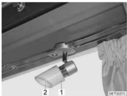
natural_image
Close-up of a mechanical component with numbered parts (1 and 2) and a label 'DE T00370' visible, no readable text or symbols beyond labels.Fig. 180 Halogen spotlight (movable)
Changing bulbs:
■ Loosen the fixing screws (Fig. 180,1).
■ Carefully remove the lamp chalice (Fig. 180,2) from the holder.
■ Remove halogen bulb.
■ Put in a new halogen bulb.
■ Reassemble the lamp in the reverse order.
13.8.2 Room lamp
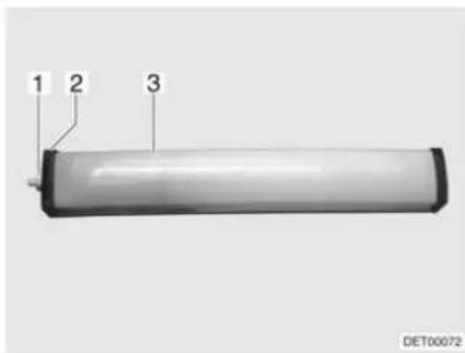
Fig. 181 Room lamp
Changing bulbs:
■ Unscrew the cap (Fig. 181,1).
■ Remove cover (Fig. 181,2).
■ Press the light covering (Fig. 181,3) lightly together and remove it.
■ Remove the fluorescent tube.
■ Insert a new fluorescent tube.
■ Reassemble the lamp in the reverse order.
13.8.3 Recessed halogen light with housing
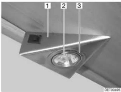
Fig. 182 Recessed halogen light
The recessed halogen light is installed flush in a housing (Fig. 182,1).
Changing bulbs:
■ Use a screwdriver to remove the inner cover ring (Fig. 182,3) from the housing.
■ Remove the cover ring with the glass.
■ Remove halogen bulb (Fig. 182,2).
■ Put in a new halogen bulb.
■ Reassemble the lamp in the reverse order.
13.8.4 Recessed halogen light (swivelling)
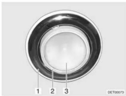
Fig. 183 Recessed halogen light (swiv-elling)
Changing bulbs:
■ Use a suitable tool (e.g. a screwdriver) to lever out and remove the lamp (Fig. 183,1).
■ Take the spotlight (Fig. 183,2) out of the lamp.
■ Remove cover (Fig. 183,3).
■ Remove halogen bulb.
■ Put in a new halogen bulb.
■ Reassemble the lamp in the reverse order.
13.8.5 Recessed halogen light (flat)
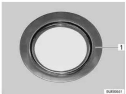
natural_image
Circular mechanical component with concentric rings and a labeled section '1', no text or symbols present.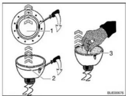
Fig. 184 Recessed halogen light (flat) Fig. 185 Changing the halogen bulb
The recessed halogen light (Fig. 184,1) is installed flush.
Changing bulbs:
■ Use a screwdriver to remove the inner cover ring (Fig. 185,1) from the housing.
■ Use a screwdriver to remove the cover ring with the glass (Fig. 185,2) from the lower section of the recessed halogen light.
■ Remove halogen bulb (Fig. 185,3).
■ Put in a new halogen bulb.
■ Reassemble the lamp in the reverse order.
13.8.6 Wardrobe light
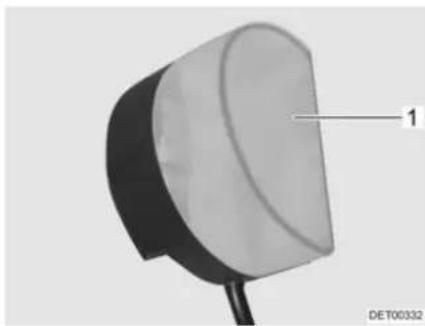
natural_image
Close-up of a mechanical component with a labeled part (1) and identifier DET00332, no readable text or symbols beyond the label.Fig. 186 Wardrobe light
Changing bulbs:
■ Press the light covering (Fig. 186,1) lightly together and remove it.
■ Remove halogen bulb.
■ Put in a new halogen bulb.
■ Reassemble the lamp in the reverse order.
13.8.7 Garage light
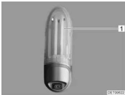
natural_image
Close-up of a transparent cylindrical device with a labeled component (no visible text or symbols on the body)Fig. 187 Garage light
Changing bulbs:
■ Push the light covering (Fig. 187,1) up slightly and remove it.
■ Remove bulb.
■ Put in a new bulb.
■ Reassemble the lamp in the reverse order.
13.8.8 Refrigerator light
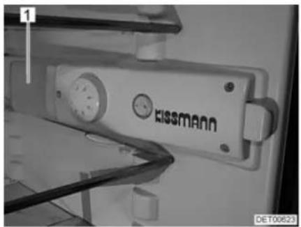
natural_image
Close-up of a Swissmann industrial device with visible wiring and components (no readable text or symbols)Fig. 188 Refrigerator light
Changing bulbs:
■ Switch off the refrigerator at the external switch.
■ Grip under the light covering (Fig. 188,1) from behind and raise the light covering approximately 3 mm.
■ Remove the light covering to the side.
■ Remove bulb.
■ Put in a new bulb.
■ Reassemble the lamp in the reverse order.
13.9 Spare parts

▶ Every alteration of the original condition of the vehicle can alter road behaviour and jeopardize road safety.
The special equipment and original spare parts recommended by Dethleffs have been specially developed and supplied for your vehicle. These products are available at the authorised dealers or service centres. The authorised dealers and service centres are informed about admissible technical details and carry out the required work correctly.
The use of accessories, parts and fittings not supplied by Dethleffs may cause damage to the vehicle and jeopardize road safety. Even if an expert's report, a general type approval or a design certification exists, there is no guarantee for the proper quality of the product.
▶ No liability can be assumed for damage caused by products which have not been released by Dethleffs. This also applies to impermissible alterations to the vehicle.
For safety reasons, spare parts for pieces of equipment must correspond with manufacturer's instructions and be permitted by the manufacturer as a spare part. These spare parts may only be fitted by the manufacturer or an authorised specialist workshop. The authorised dealers and service centres are available for any spare parts requirement.
Here are some suggestions of important spare parts:
- Fuses
• V-belt
● Windscreen blades - Bulbs
When ordering spare parts, please indicate the serial number and the vehicle type to the authorised dealer or service centre.
The vehicle described in this instruction manual is built and equipped to factory standards. Special equipment is offered depending on its purpose or use.
When fitting special equipment check if such equipment has to be entered in the vehicle documents. Observe the max. permissible gross weight. The authorised dealer or service centre will be happy to advise you.
13.10 Vehicle identification plate
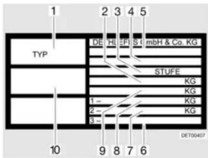
Fig. 189 Vehicle identification plate
1 Type
2 Maximum permissible gross weight of the vehicle with trailer
3 Manufacturer of the unit (add-on unit)
4 Manufacturer's code and chassis number
5 EG type approval number
6 Permissible rear axle load (for tandem axle)
7 Permissible axle load rear
8 Permissible axle load front
9 Maximum permissible gross weight of the vehicle
10 Serial number
The vehicle identification plate (Fig. 189) with the serial number is fitted on the B column on the front passenger side (models T and A) or in the entrance area (models I).
Do not remove the vehicle identification plate. The vehicle identification plate:
- Identifies the vehicle
● Helps with the procurement of spare parts
● Together with the vehicle documents identifies the vehicle owner
Always include the serial number with all inquiries for the customer service office.

13.11 Warning and information stickers
There are warning and information stickers on and inside the vehicle. Warning and information stickers are for the sake of safety and must not be removed.

Replacement stickers can be obtained from an authorised dealer or a service centre.
Chapter overview
This chapter contains instructions regarding the tyres of the vehicle.
The instructions address the following topics:
- tyre selection
- handling of tyres
- changing wheels
- spare wheel support
- tyre pressure
At the end of the chapter there is a table you can use to find the correct tyre pressure for your vehicle.
14.1 General

▶ Check tyre pressure before a journey or every 2 weeks. Wrong tyre pressure causes excessive wear and can lead to damage or even to tyre burst. You can lose control of the vehicle.

▶ Only check the tyre pressure on cold tyres.
▶ Tubeless tyres have been installed on the vehicle. Never install tubes in these tyres.
Read the instruction manual for the base vehicle.

▷ Depending on the base vehicle and model the vehicles are equipped with only one tyre repair kit as standard.
In the case of a puncture, pull over to the side of the road. Make vehicle safe with a hazard warning triangle. Switch on the warning lights.
▶ Tyres on vehicles with tandem axles may wear faster.
- Tyres must not be older than 6 years as the material will become brittle over time. The four-digit DOT number on the tyre flank indicates the date of manufacture. The first two digits designate the week, the last two digits the year of manufacture.
Example: Week 15, year of manufacture 2009.
Observe:
- Check the tyres regularly (every 2 weeks) for equal tread wear, tread depth and external damage.
■ Replace tyres at the latest, when the minimum depth of tread stipulated by law is reached.
■ Always use tyres of the same model, same brand and same style (summer and winter tyres).
■ Only use tyres approved for the wheel rim type fitted. The permitted rim and tyre sizes are quoted in the vehicle documents and the authorised dealer or service centre will always be glad to give you advice.
■ Run-in new tyres for approx. 100 km (60 miles) at low speed since only then do they reach full strength.
flowchart
graph TD
    A["Hexagon"] --> B["Hexagon"]
    B --> C["Hexagon"]
    C --> D["Hexagon"]
    D --> E["Hexagon"]
    E --> F["Hexagon"]
    F --> G["Hexagon"]
    G --> H["Hexagon"]
    H --> I["Hexagon"]
    I --> J["Hexagon"]
    J --> K["Hexagon"]
    K --> L["Hexagon"]
    L --> M["Hexagon"]
    M --> N["Hexagon"]
    N --> O["Hexagon"]
    O --> P["Hexagon"]
    P --> Q["Hexagon"]
    Q --> R["Hexagon"]
    R --> S["Hexagon"]
    S --> T["Hexagon"]
    T --> U["Hexagon"]
    U --> V["Hexagon"]
    V --> W["Hexagon"]
    W --> X["Hexagon"]
    X --> Y["Hexagon"]
    Y --> Z["Hexagon"]
Fig. 190 Tighten the wheel nuts or wheel bolts cross-wise
- Check regularly that the wheel nuts or wheel bolts are firmly seated. Retighten the wheel nuts or wheel bolts of a changed wheel cross-wise (Fig. 190) after 50 km (30 miles).
■ When using new or newly painted rims, re-tighten the wheel nuts or wheel bolts once again after approx. 1,000 to 5,000 km (600 miles to 3,000 miles).
■ For lay-ups or long periods of inactivity, keep the tyres and tyre bearings free from pressure points:
Jack up the vehicle so that the wheels do not bear any load, or move the vehicle every 4 weeks in such a way that the position of the wheels is changed.
14.2 Tyre selection


▶ A wrong tyre can damage the tyres during the journey and even cause it to burst.
▷ If tyres that are not approved for the vehicle are used, then the type approval for the vehicle and subsequently the insurance coverage can lapse. The authorised dealer or service centre will be happy to advise you.
The tyre sizes approved for the vehicle are given in the vehicle documents or can be obtained from the authorised dealers or service centres. Each tyre must fit the vehicle on which it will be driven. This applies to the external dimensions (diameter, width), which are indicated with the standardised size designations. In addition, the tyres must meet the requirements of the vehicle with regard to weight and speed.
Weight refers to the maximum permissible axle load which can be distributed on two tyres. The maximum load-carrying capacity of a tyre is indicated by its load index (= LI, load index code).
The axle geometry of a vehicle, such as wheel camber and track, is also important for tyre selection. The maximum permissible speed for a tyre (with full load-carrying capacity) is indicated by the speed index (= SI). Together, load index and speed index form the operating code of a tyre. This is an official component of the complete, standardised dimensions description which appears on every tyre. The information on the tyres must correspond to the specifications which appear in the vehicle papers.
14.3 Tyre specifications
215/70 R 15C 109/107 Q
| Description Explanation | |
| 215 Tyre width in mm | |
| 70 Height-to-width proportion in percent | |
| R Tyre design (R = radial) | |
| 15 Rim diameter in inches | |
| C Commercial (transporter) | |
| 109 Load index code for single tyres | |
| 107 Load index code for twin tyres | |
| Q Speed index (Q = 160 km/h) |
14.4 Handling of tyres
■ Drive over kerbs at an obtuse angle. Otherwise the flanks of the tyres may get pinched. Driving over a kerb at a sharp angle can damage the tyre and result in it getting ruptured.
■ Drive over high manhole covers at a slow speed. Otherwise the tyres may get pinched. Driving over a high manhole cover at high speed can damage the tyre and result in it getting ruptured.
■ Check the shock absorbers regularly. Driving with poor shock absorbers significantly increases wear.
If the tread wear is uneven, have the toe-in and the wheel camber checked. Driving with an incorrectly set toe-in or a one-sided wheel camber leads to a significant increase in wear.
■ Avoid block brakings. Block braking gives the tyres "brake plates" of varying strength. This reduces driving comfort. It might even make the tyres unserviceable.
■ Do not clean the tyres with a high-pressure cleaner. The tyres can suffer serious damage within just a few seconds and rupture as a result.
■ Drive in such a way as to protect your tyres. Avoid braking sharply, revving up too strongly and long journeys on poor roads.
14.5 Changing wheels

The vehicle must be on level, firm ground, secure from slipping.
▶ Go into first gear. In the case of automatic transmission, change gear to "P" position.
▶ Before jacking up the vehicle firmly apply the handbrake.
▶ Prevent the vehicle from rolling away by blocking the opposite wheel with the wheel chocks.
▶ Under no circumstances jack the vehicle with the fitted supports.
▶ If a trailer is connected: Detach the trailer before lifting the vehicle.
▶ Position the vehicle jack underneath the axle, not under any circumstances on the bodywork.
▶ Never overload the vehicle jack. The maximum permissible load is specified on the vehicle jack's identification plate.

▶ Use the vehicle jack only for lifting the vehicle briefly while changing the tyre.
▶ Do not start the motor while the vehicle is jacked up.
▶ Whilst the vehicle is in a jacked up position, persons must not lie down under it.

Do not damage the thread of the thread bolts when changing the wheel.
▷ Tighten the wheel nuts or wheel bolts cross-wise (Fig. 190).
When changing wheels (e.g. alloy wheel rims or wheels with winter tyres), use the correct wheel bolts of the correct length and shape. The firm seating of the wheels and the function of the braking system depend on this.
▶ Wheel rims and tyres not permitted for use with the vehicle can jeopardize road safety.
Do not replace wheels cross-wise.

▷ Protect the vehicle according to the national regulations, e.g. with a hazard warning triangle.
Before changing the wheel, check the wheel rim and tyre size, the max. tyre load and the speed index on the tyres. Only use the wheel rim and tyre sizes stated in the vehicle documents.
▶ Further information can be found in the instruction manual of the base vehicle.
14.6 Spare wheel support

▶ Due to its weight and fitted position, the spare wheel can be raised or lowered by a very strong person only. Always get a second person to assist.
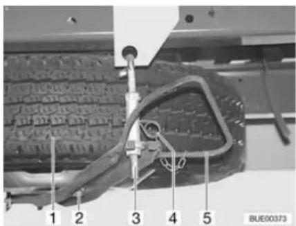
Fig. 191 Spare wheel support (Iveco)
Removing the spare wheel:
■ Pull out splint (Fig. 191,4).
■ Press the clip (Fig. 191,5) against the spare wheel and unhook the holder (Fig. 191,3).
■ Move the clip down.
■ Undo nut (Fig. 191,2) and remove the spare wheel (Fig. 191,1).
14.7 Tyre pressure

▶ Tyres overheat if the tyre pressure is too low. This can cause serious tyre damage.
▶ Check tyre pressure before a journey or every 2 weeks. Wrong tyre pressure causes excessive wear and can lead to damage or even to tyre burst. You can lose control of the vehicle.
▶ Use only valves that are approved for the specified tyre pressure.

▶ Only check the tyre pressure on cold tyres.
The payload and the durability of tyres is directly dependent on the tyre pressure. Air is a volatile medium. It is unavoidable that it will escape from tyres.
As a rule of thumb it can be assumed that a filled tyre loses pressure at a rate of 0.1 bar every two months. To prevent the tyres becoming damaged or burst, check the tyre pressure regularly.

The information on pressure levels is valid for cold tyres and loaded vehicles.
Pressure in hot tyres is higher than in cold tyres. Therefore, check the pressure when the tyres are cold.
The kg values refer to the actual axle load.
▷ Tyre pressures in bar.
The valve used must be approved for the air pressure. We recommend the use of a metal valve for pressures greater than 4.75 bar.
For the maximum permissible axle loads for your vehicle please refer to specific documentation.
| Tyre pres-sure | 225/75 R 16 C118/116 Q | 225/75 R 16 C121/120 Q | ||
| Front (kg) Rear (kg) Front (kg) Rear (kg) | ||||
| 3.0 1680 3190 -- | ||||
| 3.25 1790 3400 -- | ||||
| 3.5 1900 3610 -- | ||||
| 3.75 2010 3820 2060 3970 | ||||
| 4.0 2120 4020 2160 4180 | ||||
| 4.25 2220 4220 2270 4390 | ||||
| 4.5 2330 4410 2380 4600 | ||||
| 4.75 2430 4610 2480 4800 | ||||
| 5.0 2530 4800 2590 5000 | ||||
| 5.25 2640 5000 2690 5200 | ||||
| 5.5 | - | - | 2790 | 5400 |
| 5.75 | - | - | 2900 | 5600 |
The vehicles are constantly brought up to the newest technical standards. It is possible that new tyre sizes are not yet included in this table. If this is the case, the Dethleffs dealer will be happy to provide the newest values.
Chapter overview
This chapter contains instructions about possible faults in your vehicle.
The faults are listed with their possible causes and corresponding remedies.
The instructions address the following topics:
- braking system
- pneumatic spring
• electrical-hydraulic steady legs
- electrical system
- light control
- gas system
- gas cooker
- gas oven
- microwave oven
- heater
- boiler
- refrigerator
• air conditioning unit
- dishwasher
- water supply
- toilet
body
The specified faults can be remedied with relative ease and without a great deal of specialised knowledge. In the event that the remedies detailed in this instruction manual should not be successful, an authorised specialist workshop must find and eliminate the cause of the fault.
15.1 Braking system

▶ Have defects on the braking system immediately remedied by an authorised specialist workshop.
15.2 Pneumatic spring
15.2.1 Pneumatic spring (Goldschmidt)

▶ Have defects on the air suspension immediately remedied by an authorised specialist workshop.
If one or both air circuits are without air pressure (air cushion or pressure gauge damaged), only undertake the journey at a steady speed (max. 30 km/h) and only to the next garage (emergency running).
| Fault Cause Remedy | ||
| Compressor does not start | Fuse is defective Replace fuse | |
| Compressor motor over-heated | Allow compressor motor to cool down for approx. 30 minutes | |
| Operating switch defective | Contact customer service | |
| Thermal monitoring continuously responds | Ambient temperature is too high | Provide more ventilation |
| Compressor is defective | Contact customer service | |
| Loud noises during operation | Screwed connections of the supports loose | Check the screwed connections and tighten if necessary |
| Compressor is defective | Contact customer service | |
| Pressure drops sharply during operation | Connections loose Tighten | connections |
| System has a leak Contact | customer service | |
| Compressor does not switch off | Connections loose Tighten | connections |
| Compressor is defective | Contact customer service | |
| Operating switch defective | Contact customer service | |
15.2.2 Pneumatic spring (VB-air suspension)

▶ Have defects on the air suspension immediately remedied by an authorised specialist workshop.
| Fault Cause Remedy | ||
| Compressor not running Fuse | use is defective Replace fuse | |
| Input voltage too low Charge battery | the living area battery | |
| Vehicle is not lowered Fuse | is defective Replace fuse | |
| Vehicle is not raised, even though the compressor is running | No changeover between manual and automatic level control | Check the functionWhen the service function is activated ("SERVICE" LED lights up):Deactivate the service functionWhen the service function is not activated: Contact customer service |
15.3 Electrical-hydraulic steady legs
| Fault Cause Remedy | ||
| System does not work | Ignition not switched on | Switch on ignition |
| Handbrake not applied Apply the handbrake | ||
| Control unit switched off Press the On/Off switch | ||
| Steady legs do not extend | Input voltage too low Charge the living area battery | |
| LED indicator for battery lights up | ||
| Steady legs do not extend completely, even though the pump is running | Oil level too low Check the oil level and top up oil if necessary | |
15.4 Electrical system

When the living area battery is changed, only use batteries of the same type.

▷ See chapter 9 for changing the fuses.
| Fault Cause Remedy | ||
| Road light system does no longer work correctly | Bulb is defective Unscrew | cover of the relevant light, replace bulb. Note volts and watts specifications |
| Fuse is defective Replace fuse | ||
| Interior lighting does not work | Bulb is defective Unscrew | cover of the relevant light, replace bulb. Note volts and watts specifications |
| Fuse on the transformer/rectifier is defective | Replace fuse on the transformer/rectifier | |
| The electrically operated entrance step cannot be moved in or out | Fuse on the transformer/rectifier is defective | Replace fuse on the transformer/rectifier |
| No 240 V power supply despite connection | 240 V automatic circuit breaker has triggered | Switch on the 240 V automatic circuit breaker |
| Starter or living area battery is not charged when operated in 240 V mode | Fuse on the starter battery or on the living area battery faulty | Replace fuse on the starter battery or on the living area battery |
| Charger module in the transformer/rectifier or the auxiliary charging unit is defective | Contact customer service | |
| Living area battery is not charged during vehicle operation | Fuse on terminal D+ of the alternator is defective | Replace fuse |
| Disconnector relay in the transformer/rectifier is defective | Contact customer service | |
| No display on the panel 12 | V power supply switched off | Switch 12 V power sup-ply on |
| Living area battery dis-connected from the 12 V power supply | Connect the living area battery with the 12 V power supply | |
| Starter or living area bat-tery is not charged | Charge the starter or liv-ing area battery | |
| Disconnector relay in the transformer/rectifier is defective | Contact customer service | |
| Flat fuse (2 A) in the liv-ing area battery is defec-tive | Replace flat fuse (2 A) in the living area battery | |
| 12 V power supply does not work | 12 V power supply switched off | Switch 12 V power sup-ply on |
| Living area battery dis-connected from the 12 V power supply | Connect the living area battery with the 12 V power supply | |
| Living area battery is dis-charged | Charging the living area battery | |
| Fuse on the living area battery is defective | Replace fuse on the liv-ing area battery | |
| Disconnector relay in the transformer/rectifier is defective | Contact customer service | |
| 12 V power supply does not work in 240 V opera-tion | 12 V power supply switched off | Switch 12 V power sup-ply on |
| Living area battery dis-connected from the 12 V power supply | Connect the living area battery with the 12 V power supply | |
| Charger module in the transformer/rectifier or the auxiliary charging unit is defective | Contact customer service | |
| 240 V automatic circuit breaker has triggered | Contact customer service | |
| Fuse on the living area battery is defective | Replace fuse on the liv-ing area battery | |
| Starter battery is dis-charged in 12 V opera-tion | Disconnector relay in the transformer/rectifier is defective | Contact customer service |
| Living area battery dis-connected from the 12 V power supply | Connect the living area battery with the 12 V power supply | |
| No voltage is supplied by the living area battery | Living area battery is discharged | Charge living area battery immediatelyTotal discharge damages the battery.If the vehicle is to be laid up for a long period, fully charge the living area battery beforehand |
| No output voltage at the converter ("Power Status" LED shows a fault) | Input voltage too high (rapid flashing) | Check input voltage |
| Input voltage too low (slow flashing) | Recharge battery | |
| Check cables and connections | ||
| Thermal overload (periodical flashing) | Switch off converter and appliances, and switch back on again after approx. 5 to 10 minutes | |
| Improve ventilation | ||
| Short circuit, incorrect polarity or excessive continuous load (continuous lighting) | Switch off the converter and remove the appliance. If no fault occurs after switching back on without an appliance, it is the appliance that is defective. If the fault still occurs, contact customer service | |
| Extractor hood does not work | 240 V automatic circuit breaker is switched off | Switch on the 240 V automatic circuit breaker |
| Fuse on the transformer/ rectifier is defective | Replace fuse | |
| Extractor hood defective C | Contact customer service | |
| Air conditioning unit cannot be switched on or off | 240 V automatic circuit breaker has triggered | Switch on the 240 V automatic circuit breaker |
| Remote control battery is empty | Change remote control battery | |
15.5 Light control

In most cases, a fault in the light control is due to defective lights or fuses. Before checking the light control for faults, check the fuses and bulbs.
| Fault Cause Remedy | ||
| None of the lamps can be operated | No supply voltage Check v | voltage supply fuses |
| Check power cables for cable break | ||
| Check the connections on the control unit and on the power supply | ||
| Control unit defective Cont | act customer service | |
| Single lamp cannot be operated | Bulb is defective Replace bulb | |
| Cable to the lamp defec-tive | Check cable for short cir-cuits or breaks | |
| Inspect the connections | ||
| No supply voltage in the corresponding circuit | Check voltage supply fuse in the corresponding circuit | |
| Check power cable in the corresponding circuit | ||
| Check the connections on the control unit and on the power supply | ||
| Switch does not work | Cable defective | Check cable for short cir-cuits or breaks |
| Check the connections on the switch and on the control unit | ||
| Switch faulty Contact custo | mer service | |
15.6 Gas system

In case of a defect of the gas system (gas odour, high gas consumption) there is danger of explosion! Close regulator tap on the gas bottle immediately. Open doors and windows and ventilate well.
If the gas system is defective: Do not smoke; do not ignite any open flames, and do not operate electric switches (light switches etc.).
▶ Have the defective gas system repaired by an authorised specialist workshop.
| Fault Cause Remedy | ||
| No gas Gas bottle is empty | Change gas bottle | |
| Gas isolator tap closed Open the gas isolator tap | ||
| Regulator tap on the gas bottle is closed | Open regulator tap on the gas bottle | |
| External temperature is too low (-42 °C for propane gas, 0 °C for butane gas) | Wait for higher external temperatures | |
| Built-in appliance is defective | Contact customer service | |
15.7 Cooker
15.7.1 Gas cooker/gas oven
| Fault Cause Remedy | ||
| Ignition fuse does not operate (flame does not burn after the control knobs are released) | Heat-up time is too short K | Keep control knobpressed for approx. 15 to20 seconds after ignition |
| Ignition fuse is defective C | Contact customer service | |
| Flame extinguishes when being reduced to its minimum setting | Thermocouple sensor is incorrectly set | Correctly reset thermocouple sensor (do not bend). The sensor tip should protrude by 5 mm beyond the burner. The sensor neck should not be more than 3 mm away from the burner ring; if necessary, contact customer service |
15.7.2 Microwave oven

▶ Only qualified personnel may repair the microwave oven. Improper repairs can cause major risks to the user.
| Fault Cause Remedy | ||
| Microwave oven does not cut in | Fuse is defective Replace fuse | |
| Door of the microwave oven is not properly closed | Remove foreign bodies stuck in the door of the microwave oven and close door properly | |
15.8 Heater/boiler

▷ If a fault occurs in the system, the cause is shown on the display.
In the event of a defect contact the nearest customer service workshop of the relevant appliance manufacturer. The list of addresses is enclosed with the accompanying appliance documentation. Only authorised qualified personnel may repair the appliance.
| Fault Cause Remedy | ||
| Heater does not ignite with gas operation | Lack of gas Open regulator | tap and gas isolator tap |
| Connect a full gas bottle | ||
| Heater does not ignite | Battery voltage too low | Charge battery. If the battery voltage rises above 11 V, the heater is switched on automatically-ly |
| Heater does not ignite at 240 V electrical operation | No 240 V power supply Switch on the 240 V automatic circuit breaker | |
| Heater switches off Overheating Allow the heater to cool. | ||
| Heater running, but no heat at the convectors | Circulating pump does not work | To reset the display, interrupt the 12 V power supply to the heater and switch it back on again |
| Switch on room thermostat | ||
| Contact customer service | ||
| Heater and circulating pump running, but no heat at the convectors | Air in the heating system Bleed hot-water heater | |
15.9 Refrigerator
In the event of a defect contact the nearest customer service workshop of the relevant appliance manufacturer. The list of addresses is enclosed with the accompanying appliance documentation. Only authorised qualified personnel may repair the appliance
15.9.1 Refrigerator with AES
| Fault Cause Remedy | |||
| Indicator lamps "230 V", "12 V" or "AUTO" are not lit green | Refrigerator is turned off S | switch on the refrigerator with energy selector switch | |
| No electrical operating voltage | Connect 240 V power supply | ||
| Let the vehicle engine run | |||
| Switch on or replace the fuse | |||
| Contact a specialist workshop | |||
| Refrigerator does not switch to 12 V mode during the journey | Operating voltage of alternator is not present/ too low | Contact a specialist workshop | |
| Refrigerator does not switch on in gas operation, "GAS" indicator lamp is not lit yellow | Lack of gas Open regulator tap and gas isolator tap | ||
| Connect a full gas bottle | |||
| Cobwebs or burnt residue in the burning chamber | Remove the ventilation grill on the outside of the vehicle and clean the burning chamber | ||
| "GAS" indicator lamp flashes yellow, no gas | Air in the gas pipe Switch off | the refrigerator with energy selector switch | |
| Open regulator tap on the gas bottle and the gas isolator tap of the refrigerator | |||
| Switch on the refrigerator with energy selector switch. After 10 seconds, the AES will attempt another ignition | |||
| If the "GAS" indicator lamp flashes yellow again after approx. 30 seconds, the failure has not been remedied yet | |||
| Repeat this process two to three times for ventilation. If the refrigerator cannot be operated, contact customer services | |||
15.9.2 Kissmann refrigerator
| Fault Cause Remedy | ||
| Refrigerator does not work | Refrigerator is turned off Switch on the refrigerator (external and internal switch) | |
| No electrical operating voltage | Connect 240 V power supply | |
| Let the vehicle engine run | ||
| Check fuse, replace if necessary | ||
| Contact a specialist workshop | ||
| Interior lighting does not work | Refrigerator is turned off Switch on the refrigerator (external and internal switch) | |
| Bulb is defective Changing the bulb | ||
| Refrigerator does not refrigerate correctly | Temperature controller set too low | Adjust the temperature controller |
| Ventilation insufficient Clean the ventilation slots | ||
| Operating noises too loud | Nearby furniture vibrates Check the attachment or straighten the refrigerator | |
15.10 Air conditioning unit
| Fault Cause Remedy | ||
| Air conditioning unit does not cool | No 240 V power supply Con | connect 240 V power supply |
| Fuse is defective Check fuse and replace if necessary | ||
| Temperature below 16 °C | ||
| Temperature has been set incorrectly | Adjust the temperature | |
| Air filter contaminated Replace air filter | ||
15.11 Dishwasher
| Fault Cause Remedy | ||
| Dishwasher does not start | Dishwasher switched off S | Switch on the dishwasher |
| 240 V automatic circuit breaker has triggered | Switch on the 240 V automatic circuit breaker | |
| 240 V operating voltage too low | Have the 240 V power supply checked by an authorised specialist work-shop | |
| Dishwasher door is not shut properly | Shut the dishwasher door | |
| Water pump is switched off | Activate water pump (see chapter 12) | |
| Fuse for water pump is defective | Replace fuse on the transformer/rectifier | |
| Button for delayed start is pressed in | Wait for set time | |
| Dishwasher takes in no water (Program display of the selected washing program flashes. Display shows as error code: 10) | No water intake Open water tap | |
| Water is not pumped off at the end of the program (Program display of the selected washing pro-gram flashes. Display shows as error code: 20) | Door opened before end of program | Restart the program |
| No water drainage Check the waste water system of the vehicle | ||
| Cleaning result poor | Spray arm stuck | Make the spray arm rotatable |
| Openings on the spray arm blocked | Clean the spray arm | |
| Filter blocked Clean the filter | ||
| Incorrect cleaning agent dosing | Adjust the dosing | |
| Rinsing liquid empty Top up rinsing liquid | ||
15.12 Water supply
| Fault Cause Remedy | ||
| Leakage water inside the vehicle | A leak has occurred Identify leak, re-connect water pipes | |
| No water Water tank is empty | Replenish drinking water | |
| Drain cock not closed Close drain cock | ||
| 12 V power supply switched off | Switch 12 V power supply on | |
| Fuse of the water pump is defective | Replace fuse on the transformer/rectifier | |
| Water pump defective Exchange water pump (have it exchanged) | ||
| Water pipe snapped off Straighten water pipe or replace | ||
| Transformer/rectifier defective | Contact customer service | |
| Water pump switched off on panel | Switch water pump on | |
| Toilet has no flush water | Water tank is empty | Replenish drinking water |
| Fuse for toilet is defective Replace fuse | ||
| Display for water and waste water indicates a wrong value | Measuring probe in the waste water or water tank is soiled | Clean water/waste water tank |
| Measuring probe is defective | Replace measuring probe | |
| Waste water tank cannot be emptied | Drain cock is clogged Open the cleaning cap on the waste water tank and drain the waste water. Rinse the waste water tank well | |
| Drain on the single lever mixer tap is clogged | Perlator calcified Unclip the perlator, de-calcify in vinegar water (only for products made from metal) | |
| Water jets on the shower nozzle clogged | Water jets calcified | De-calcify shower nozzle in vinegar water (only for products made from metal) or rub off soft nozzle burling |
| Water drains from the shower tray slowly or does not drain at all | The vehicle is not in a horizontal position | Position the vehicle horizontally |
| Milkiness of the water | Tank filled with dirty water | Clean water tank mechanically and chemically; then disinfect and rinse copiously with drinking water |
| Residues in the water tank or water system | Clean water system mechanically and chemically; then disinfect and rinse copiously with drinking water | |
| Any change in the taste or odour of the water | Tank filled with dirty water | Clean water system mechanically and chemically; then disinfect and rinse copiously with drinking water |
| Fuel filled into the water tank by mistake | Clean water system mechanically and chemically; then disinfect and rinse copiously with drinking water. If not successful: Contact a specialist workshop | |
| Microbiological deposits in the water system | Clean water system mechanically and chemically; then disinfect and rinse copiously with drinking water | |
| Deposits in the water tank and/or water-carrying components | Water excessively long in the water tank and in water-carrying components | Clean water system mechanically and chemically; then disinfect and rinse copiously with drinking water |
15.13 Vacuum toilet (Dometic)
| Fault Cause Remedy | ||
| Water does not remain in toilet bowl | Seal dirty or defective Clean seal or have replaced | |
| Water does not flow properly into the toilet bowl | Water pressure too low Contact customer service | |
| Water is entering the vehicle | Hose connection loosened | Check connections for proper seat and tighten hose clamps |
| Vacuum pump does not run | No power present Control power supply (or have checked) | |
| Vacuum pump runs too often | Cap or connection not sealed tightly | Check connections between toilet and vacuum (or have checked) |
| Toilet clogged Improper used | Remove blockage | |
15.14 Body
| Fault Cause Remedy | ||
| Flap hinges/door hinges are difficult to operate | Flap/door hinges are not sufficiently lubricated | Lubricate flap hinges/door hinges with acid-free and resin-free grease |
| Hinges/joints in the bathroom unit/toilet compartment are difficult to operate/make a grating noise | Hinges/joints are not sufficiently lubricated | Lubricate hinges/joints with solvent-free and acid-free grease ▷ Spray cans often contain solvents |
| Storage compartment hinges are difficult to operate/make a grating noise | Storage compartment hinges are not sufficiently lubricated | Lubricate storage compartment hinges with acid-free and resin-free grease |
| Front bonnet swivel system is difficult to operate | Front bonnet swivel system is not (sufficiently) lubricated | Lubricate front bonnet swivel system with acid-free and resin-free grease |
| Heki skylight difficult to operate | Threaded spindle not lubricated | Lubricate threaded spindle |
| Threaded spindle defective | Have threaded spindle replaced |

The authorised dealers and service centres are available for any spare parts requirement.
16.1 Weight details for special equipment

The use of accessories, parts and fittings not supplied by Dethleffs may cause damage to the vehicle and jeopardize road safety. Even if an expert's report, a general type approval or a design certification exists, there is no guarantee for the proper quality of the product.
▶ Every alteration of the original condition of the vehicle can alter road behaviour and jeopardize road safety.
▶ No liability can be assumed for damage caused by products which have not been released by Dethleffs. This also applies to impermissible alterations to the vehicle.
Weight details for Dethleffs special equipment are listed in the table below. If these objects are either carried in or on the vehicle and are not part of the standard equipment, they must be taken into consideration when calculating the payload.
All weight details are approximate.
Observe the max. permissible gross weight.
| Item designation Surplus weight (kg) | |
| Caravan coupling 26 | |
| External shower (cold water) 1 | |
| Automatic transmission 5 | |
| Car radio and CD 2 | |
| Oven 14 | |
| Battery 220 Ah „Gel“ battery 25 | |
| Skylight 1 | |
| Roof rail 10 | |
| Roof rack with aluminium ladder 17 | |
| "Kissenschlacht" (pillow fight) decoration package 1 | |
| Extractor hood | 2 |
| DuoControl switching facility (incl. 11 kg gas bottle) | 26 |
| Bike rack for 2 bicycles in rear garage | 3 |
| Bike rack for 3 bicycles | 9 |
| Bike rack for 4 bicycles | 10 |
| Flat screen | 5 |
| External gas socket | 1 |
| Holder for flat screen | 5 |
| Heki 3 | 15-22 |
| Insect screen, conversion door | 3 |
| Insulation mat for driver's cabin window | 1 |
| Air conditioning unit | 32 |
| Refrigerator, separate freezer compartment | 20 |
| Pneumatic spring | 30 |
| Awning, 450 cm | 32 |
| Awning, 500 cm 36 | |
| Awning, electric, 550 cm 65 | |
| Awning, electric, 600 cm 75 | |
| Microwave oven 15 | |
| Navigation system 2 | |
| Crossbeams and ladder for roof rail 7 | |
| Radio preparation 1 | |
| Reversing camera 5 | |
| Satellite unit 15-23 | |
| Switch for water pump 1 | |
| Service flap 3 | |
| Safety kit 15 | |
| Solar installation 15 | |
| Transformer for air conditioning unit 3 | |
| Fabric panelling, inside | 2 |
| Rear supports (2 pcs.) 6 | |
| Thetford spare cassette | 2 |
| Sill | 3 |
| Cables for reversing camera | 3 |
| Awning light | 1 |
| Hazard warning triangle and first-aid kit | 2 |
| Winter covering for the refrigerator grating | 1 |
| Auxiliary battery 95 Ah | 27 |
| Additional heater, driver's cabin (independent vehicle heater) | 7 |
| Auxiliary lamps, inside 2 | |
| Additional pump 240 V (Alde heater) | 1 |
Chapter overview
This chapter contains helpful tips for the journey.
The instructions address the following topics:
• road assistance in European countries
● traffic rules in European countries
• gas supply in European countries
- toll regulations in European countries
● safe ways to spend the night during travel
- camping in winter
At the end of the chapter there is a checklist containing the most important equipment for the journey.
17.1 Traffic rules in foreign countries

The vehicle driver is required to inform himself as to the traffic rules of the countries in which he plans to travel before beginning the trip. Contact your automobile club or embassy for further information.
In some European countries, warning vests must be worn when exiting the vehicle outside of towns in the case of vehicle failures or accidents.
Information about traffic regulations is especially important as state law applies in case of damage. For your own safety, always observe the following rules when travelling abroad:
• Take the green insurance card with you.
● Always register accidents with the police.
- Never sign documents that you have not read and understood completely.
17.2 Help on Europe's roads
| Country Emergen- | +cy services★ Police | Breakdown service |
| Belgium 112 | +★ 112 | TCB Brussels 0 70 34 47 77 |
| Bulgaria 150 | +★ 166 | UAB (02) 9 80 33 08/146 ^1) |
| Denmark 112 | +free of charge★ 112free of charge | Falck 79 42 42 42 |
| Germany 112 | +★ 110 | ADAC 22 22 22 ^1) |
| Estonia 112 | +★ 110/112 ^1) | EESTI (0) 6 97 91 88/18 88 ^1) |
| Finland 112 | +★ 112 | Helsinki (09) 77 47 64 00 |
| France | + 15/112 ^1) ★ 17/112 ^1) | Lyon (08) 25 80 08 22AIT-Assistance 0800 08 92 22 |
| Greece 112 | +★ 171/112^1) | ELPA 104 00 |
| Great Britain 112 | +★ 112 | AA (08 00) 0 28 90 18/(08 00) 82 82 82^1) |
| Ireland | + 999/112^1) ★ 999/112^1) | AA Dublin 18 00 66 77 88 |
| Iceland 112 | +★ 112 | F.I.B 5 11 21 12 |
| Italy | + 118/112^1) ★ 112 | ACI 803 116/8 00 11 68 00^1) |
| Croatia | + 94/112^1) ★ 92/112^1) | HAK 9 87/ 0 19 87^1) |
| Latvia | + 03/112^1) ★ 02/112^1) | LAMB 8 00 00 00 |
| Lithuania | + 03/112^1) ★ 02/112^1) | LAS 8 80 00 00 00/18 88^1) |
| Luxembourg 112 | +★ 113/112^1) | ACL 2 60 00 |
| Macedonia 194 | +★ 192 | AMSM 196 |
| Montenegro 94 | +★ 92 | AMSCG 9807 |
| Netherlands 112 | +★ 112 | ANWB 08 82 69 28 88 |
| Norway 113 | +★ 112 | NAF 81 00 05 05 |
| Austria | + 144/112^1) ★ 133/112^1) | ÖAMTC 120 |
| Poland | + 999/112^1) ★ 997/112^1) | PZM 022 5 32 84 33 |
| Portugal 112 | +★ 112 | ACP Lissab. (21) 9 42 91 03ACP Porto (22) 8 34 00 01 |
| Romania | + 961/112^1) ★ 955/112^1) | ACR (021) 2 22 22 22/(021) 2 22 15 53^1) |
| Russia 03 | +★ 02 | RAS (4 95) 7 47 66 66 |
| Sweden 112 | +★ 112 | M 0 20 91 29 12 |
| Switzerland 144 | +★ 117/112^1) | TCS 1 40/03 18 50 53 11^1) |
| Serbia 94 | +★ 92 | AMSS (011) 19800 |
| Slovakia | +155/112^1) ★ 158/112^1) | SATC 1 81 24 |
| Slovenia 112 | +★ 113 | AMZS (1) 9 87/(003861) 5 30 53 53^1) |
| Spain 061 | +★ 112 | RACE 9 15 93 33 33 |
| Czech Republic | +155/112^1) ★ 158/112^1) | UAMK CR 12 30 |
| Turkey 112 | +★ 155/112^1) | TTOK (02 12) 2 82 81 40 |
| Ukraine 03 | +★ 02 | 112 UA (8-032) 2 97 81 12 |
| Hungary | +104/112^1) ★ 107/112^1) | MAK1 88/(0036-1) 13 45 17 44^1) |
| Cyprus 112 | +★ 112 | AA 02 22 31 31 31 |
1) In the mobile communication network
Date 03/2007
Specifications without guarantee
17.3 Speed limits and permissible dimensions

▶ Please always observe the speed limits in the individual countries.
For information, the speed limits (in km/h) and permissible dimensions (in m) of the countries visited most:
| Country Max. dimensions in metersWidth Lgth. | Gross weight | In built-up areas | Outside built-up areas | Motor-way | ||
| Belgium 2.55 | 12 Up to 7.5 t | Over 7.5 t | 50 | 90/120^1) | 120 | |
| 50 | 60/90^1) | 90 | ||||
| Bulgaria 2.60 | 12 Up to 3.5 t | Over 3.5 t | 50 | 90 | 130 | |
| 50 | 70 | 100 | ||||
| Denmark 2.55 | 12 Up to 3.5 t | Over 3.5 t | 50 | 80 | 130 | |
| 50 | 70 | 80 | ||||
| Germany 2.55 | 12 Up to 3.5 t | 3.5 t up to 7.5 t | 50 | 100 | 130^3) | |
| 50 | 80 | 100 | ||||
| Over 7.5t^2) | 50 | 80 | 80 | |||
| Estonia 2.50 | 12 Up to 3.5 t | Over 3.5 t | 50 | 90 | 110 | |
| 50 | 70 | 70 | ||||
| Finland 2.60 | 12 50 | 80^4) | 80^4) | |||
| France 2.55 | 12 Up to 3.5 t | Over 3.5 t | 50 | 90^5)/-80^5)/100^1)5) | 130^5)110^5) | |
| 50 | ||||||
| Greece | 2.50 12 50 | 90/110^11) | 120 | |||
| Great Britain | 2.55 12 48 | 96/112^1) | 112 | |||
| Ireland | 2.55 12 50 | 60/100^1) | 120 | |||
| Iceland | 2.55 12 50 | 90^6) | - | |||
| Italy | 2.50 | 12 | Up to 3.5 t | 50 | 90/110^1)7) | 130^7) |
| Over 3.5 t | 50 | 80 | 100 | |||
| Croatia | 2.55 12 50 | 90/110^1) | 130 | |||
| Latvia | 2.50 | 12 | Up to 7.5 t | 50 | 90/100^11) | 110 |
| Over 7.5 t | 50 | 80 | 80 | |||
| Lithuania | 2.50 | 12 | Up to 3.5 t | 50 | 90 | 110 |
| Over 3.5 t | 50 | 70 | 70 | |||
| Luxembourg | 2.55 12 | Up to 3.5 t | Over 3.5 t | 50 | 90^8)7) | 130^8)7) |
| 50 | 75^7) | 90^7) | ||||
| Macedonia | 2.50 | 12 | 40/60 | 80 | 80 | |
| Montenegro | 2.50 12 | Up to 3.5 t | 50 | 80/100^1) | 100 | |
| Over 3.5 t | 50 | 80 | 80 | |||
| Netherlands | 2.55^9) | 12 Up to 3.5 t | Over 3.5 t | 50 | 80/100^1) | 120 |
| 50 | 80 | 80 | ||||
| Norway | 2.55 | 12.40 | Up to 3.5 t | 50 | 80/90^1) | 90 |
| Over 3.5 t | 50 | 80 | 80 | |||
| Country | Max. dimen-sions in me- ters | Gross weight | In built-up areas | Outside built-up areas | Motor-way | |
| Width | Lgth. | |||||
| Austria 2.55 | 12 Up to | 3.5 t | 50 | 100 | 130^10) | |
| Over 3.5 t | 50 | 70 | 80 | |||
| Poland 2.50 | 12 Up to | 3.5 t | 50 | 90/100^1) | 130 | |
| Over 3.5 t | 50 | 70/80^1) | 80 | |||
| Portugal 2.50 | 12 Up to | 3.5 t | 50 | 90/100^11) | 120^12) | |
| Over 3.5 t | 50 | 80/90^11) | 110^12) | |||
| Romania 2.50 | 12 Up to | 3.5 t | 50 | 80/90^1) | 120 | |
| Over 3.5 t | 50 | 80/90^1) | 110 | |||
| Russia 2.50 | 12 Up to | 3.5 t | 60 | 90^13) | 110^13) | |
| Over 3.5 t | 60 | 70 | 90^13) | |||
| Sweden 2.60 | 24^14) | Up to 3.5 t | 50 | 70-110^1)^11) | 110 | |
| Over 3.5 t | 50 | 80/90^1) | 90 | |||
| Switzer-land | 2.55 12 | Up to 3.5 t | 50 | 80/100^1) | 120 | |
| Over 3.5t^15) | 50 | 80/100^1) | 100 | |||
| Serbia and Mon- tenegro | 2.50 12 | Up to 3.5 t | 60 | 80/100^1) | 100 | |
| Over 3.5 t | 60 | 80 | 80 | |||
| Slovakia 2.50 | 12 Up to | 3.5 t | 60 | 90 | 130 | |
| Over 3.5 t | 60 | 80 | 80 | |||
| Slovenia 2.55 | 12 Up to | 3.5 t | 50 | 80/100^1) | 100 | |
| Over 3.5 t | 50 | 80 | 80 | |||
| Spain 2.55 | 12 50 | 70/80^1) | 90 | |||
| Czech Re- public | 2.50 12 | Up to 3.5 t | 50 | 90 | 130 | |
| Over 3.5 t | 50 | 80 | 80 | |||
| Turkey 2.50 | 10 50 80 | 90 | ||||
| Ukraine | 2.50 12 | 60 | 90^13) | 110^13) | ||
| Hungary 2.50 | 12 Up to | 2.5 t | 50 | 90/110^1) | 130 | |
| Over 2.5 t | 50 | 70 | 80 | |||
| Cyprus 2.55 | 12 50 80 | 100 | ||||
1) On expressways, on roads with more than one lane in each direction
2) Vehicles over 7.5 tons max. permissible weight require a tachograph
3) Recommended speed: 130 km/h
4) Since 1995, for the first time, vehicles up to an unladen weight of 1875 kg and vehicles up to 3.5 t perm gross weight with appropriate equipment (ABS, driver airbag, seat belts on all seats) can drive max. 100 km/h
5) On wet roads, reduce speed by 10 km/h, on motorways by 20 km/h
6) On unmade roads (gravel): 80 km/h
7) In wet conditions, reduce speed by 20 km/h
8) Drivers who don't have their driver's licence for the full year, must not drive faster than max. 75 km/h when out of town or 90 km/h on motorways
9) On main roads 2.55 m, on roads marked "B" 2.20 m
10) Between 10 p.m. and 5 a.m. the speed limit on the following motorways is 100 km/h: A10 (Tauernautobahn), A12 (Inntalautobahn), A13 (Brennerautobahn), A14 (Rheintalautobahn)
11) According to traffic signs
^12) Drivers who have had their driver's licence for less than one year must not drive faster than 90 km/h. Corresponding stickers (available from ACP offices) must be affixed in a clearly visible position on the rear of the vehicle
^13) Drivers who have had their driver's licence for less than two years must not drive faster than 70 km/h
^14) Swedish campsites often require the motorhome to have a closed waste water system
^15) A heavy goods vehicle supplement must be paid on all roads for all vehicles exceeding 3.5 tons max. permissible weight
Date 06/2008
Source: ADAC
Specifications without guarantee
17.4 Driving with low beam in European countries

In many European countries, it is compulsory to drive with the vehicle's lights on even during the day. Regulations vary between countries. Motoring organisations or consulates can provide you with the relevant information.
17.5 Sleeping in the vehicle away from camping areas
| Country Sleeping on roads and fieldsYes No Yes No | Sleeping on privately owned lands | Comments | ||
| Belgium X X On | highway rest areas | max. 24 hours permitted | ||
| Bulgaria X X | ||||
| Denmark X X On | streets and squares only up | to 11 hours with a parking disc | ||
| Germany X X Staying overnight for one night | to restore driving ability is per- mitted. There may be regional and local limitations | |||
| Finland | X | X | Possible with the permission of the land owner | |
| France | X | X | Permission from the local au- thorities or the owner of the land is required. Parking and staying overnight on free areas is pro- hibited | |
| Greece | X | X | Staying overnight for one night at designated areas on the na- tional route Patras-Athens- Thessaloniki is permitted | |
| Great Britain | XX | |||
| Country | Sleeping on roads and fields | Sleeping on privately owned lands | Comments | ||
| Yes | No | Yes | No | ||
| Ireland X X | |||||
| Italy X X Staying | overnight for one night | at car parks and service stations is allowed. Observe the local regulations. Parking and staying overnight on free areas is prohibited | |||
| Croatia X X | |||||
| Luxembourg X X | |||||
| Macedonia X X | |||||
| Netherlands X X | Overnight stays on streets and | squares is allowed in some bor-oughs | |||
| Norway X X Officially prohibited on rest are- | as and cultivated grounds. Trav-elling on dirt roads is prohibited | ||||
| Austria X X Staying overnight for one night | to restore driving ability is per-mitted, but not in nature re-serves. Observe regional and local restrictions. Generally forbidden in Tyrol | ||||
| Poland X X Requires property owner's per- | mission | ||||
| Portugal | X | X | Staying overnight for one night on motorway service stations and car parks under 10 hours are tolerated | ||
| Romania | XX | ||||
| Russia X X | |||||
| Sweden | X | X | Not on agriculture areas or in the vicinity of houses. Driving on open fields is prohibited | ||
| Switzerland X X | One overnight stay at highway | rest areas and in some cantons is tolerated | |||
| Serbia and Montenegro | X | X | |||
| Slovakia | X | X | Overnight stays on private land are only allowed if a toilet is present | ||
| Slovenia | XX | ||||
| Spain | X | X | Some regional prohibitions ap-ply, especially on beaches | ||
| Czech Repub-lic | XX | Overnight stays on private land are only allowed if a toilet is present | |||
| Country Sleeping | onroads andfields | Sleeping onprivatelyownedlands | Comments | ||
| Yes No | Yes No | ||||
| Turkey X X | |||||
| Ukraine X X | |||||
| Hungary X X Staying overnight on privately | owned land is permitted onlywith police certification | ||||
Specifications without guarantee
17.6 Gas supply in European countries

In Europe, there are several different connection systems for gas bottles. It is not always possible to fill or exchange your gas bottles in a foreign country. Get information about the connection system in the country you are travelling to before embarking on your journey, e.g. at a motoring club or in the trade press.
General tips Always observe the following instructions:
- Only go on vacation with completely filled gas bottles.
- Use all of the gas bottles' capacity.
- Take along adapter sets (available in camping supply stores) for filling gas bottles in foreign countries and for connecting the gas pressure regulator to foreign gas bottles.
- During the cold time of the year observe filling with propane gas component (butane does not gas below 0 °C).
- Use blue bottles from the firm Campingaz (distributed world-wide). Only use gas bottles with safety valves.
- When bottles from other countries are used, check the gas bottle compartments to see if the gas bottles fit into them. Gas bottles from other countries do not always display the same size as your own gas bottles.
17.7 Toll regulations in European countries
Many European countries have introduced a mandatory toll system. The toll regulations and how they are collected vary greatly from country to country. Nevertheless, ignorance is no excuse. Penalties can be quite severe.
As is the case with traffic regulations, the vehicle driver is required to be familiar with the toll formalities before starting out on a trip. For example, in Austria the vignette does not meet the toll requirements for vehicles that weigh more than 3.5 t. There, a so-called "Go-Box" must be obtained and charged. Contact your automobile club or the Internet for further information.

▷ Windscreens with solar filters can affect the functioning of automatic toll collection systems (e.g. Go-Box). This must be taken into account when acquiring the appropriate device (e.g. Split-Go-Box).
17.8 Tips on staying overnight safely during travel
Prudent behaviour is the most important protective measure for insuring a safe night in the motorhome.
The risk of thievery is reduced to a minimum when the following basic rules are observed:
- Before commencing the journey, close and lock all windows, doors and skylights.
- During high season do not spend the night at highway rest stops or parking areas located along typical vacation routes.
- Several vehicles on one site at the same time do not necessarily decrease the chances of thievery occurring. Consult your own feelings about the parking site.
● Even if it is just for one night, go to a camping site. - When parking on open space keep emergency routes clear. The way to the driver's seat should be clear. The ignition key should always be within reach.
- Only take with you those valuables which are absolutely necessary for the journey. If possible, store valuables in a small safe and not in the immediate vicinity of windows or doors.
• Always lock up the vehicle.
17.9 Tips for winter campers
The following tips will help make your winter camping experience as agreeable as possible.
- Reserve your parking place in good time. Good winter camping sites are often booked up early.
- Do not start your trip without winter tyres.
- Bring snow chains.
- Choose your parking place with care. Observe the ground beneath you. Snow and ice may melt.
- When the vehicle has been positioned, release the handbrake to prevent freezing.
● No snow walls should be allowed to cover the built-in forced ventilation. - Keep the built-in forced ventilation free from snow and ice.
● Make sure the air circulation is good. Good air circulation prevents moisture from collecting and makes it easier to heat the living area. - Cover the single-paned driver's cabin window with insulation mats to avoid thermal bridges.
- Follow the instructions in the section "Gas supply in European countries".
- Use a two-bottle system with automatic controller for the gas system, so that the supply does not run out during the night.
- Only operate the gas system using propane gas.
- Do not use the space behind the heater as a storage compartment.
- Never operate catalytic ovens or infra-red gas radiators in the interior of the vehicle, since they consume oxygen for burning.
- Lay the 240 V power cable in such a way that the cable cannot be frozen or be damaged (e.g. during snow removal).
- When it is snowing heavily, clear the roof of the vehicle of snow regularly. A few centimetres of powdery snow serves as insulation, but wet snow quickly becomes a heavy burden.
- Before embarking on the return journey, remove all the snow from the roof to avoid impeding vehicles behind you with a "snow flag".
17.10 Travel checklists
The following checklists will help that nothing important is left at home although not everything on the checklists might be necessary.

Kitchen area
Do not leave checking of documents (e.g. vehicle papers and information) as well as checking the condition of the vehicle until just before commencing the trip. Planning and checking documents well in advance will save unnecessary trouble.
| √ | Object Object Object | √ | √ | ||
| Wiping cloth Cleansing agent(detergent) | Salad servers | ||||
| Mug Dishcloths Chopping board | |||||
| Turnspit Set of knives and forks for grilling | Bowls | ||||
| Can opener Coffeepot Brush to wash the dishes | |||||
| Egg-cup Corkscrew Cloth to wash the dishes | |||||
| Ice cube tray Kitchen paper Matches | |||||
| Lighter Spoons Cups | |||||
| Bottle opener | Knifes | Plates | |||
| Air-tight storage boxes | Garbage bags | Thermos jug | |||
| Breakfast plate | Frying pans Pots | ||||
| Forks | Stirring spoons | Glasses | |||
Bathroom/sanitary items
| TowelsSanitary items | Toilet brushToilet paper | Toothbrush glass |
Living area
| Dustbin | Insect lamp | Rain clothes | |||
| Road atlas | Insect repellent | First aid kit | |||
| Bath towels | Deck of cards | Travel guides/parking guide | |||
| Bath shoes | Broom | Rucksack | |||
| Batteries | Candles Sleeping bags | ||||
| Bed sheets | Dust pan | Pencils and paper | |||
| Bed linen | Coat-hangers | Shoes | |||
| Laundry bag | Clothes brush Shoe polish | ||||
| Books | Pillow | Vacuum cleaner | |||
| Camping guide | Map Flash light | ||||
| Spare bulbs | Medicine | Pocket knife | |||
| Water bottle | Music cassettes | Table cloth | |||
| Binoculars | Neck-supporting pillow | Clothes pins | |||
| Fire extinguisher | Sewing kit | Clothesline | |||
| Gas bottle Radio |
Vehicle/tools
| √ | Object | √ | Object | √ | Object |
| Waste water con-tainer | Fabric tape Screwdriver | ||||
| Adapter socket Watering can for drinking water | Current-measuring instrument | ||||
| CEE adapter Cable reel Step | |||||
| Wire V-belt Wheel chocks | |||||
| Spare wheel Glue First-aid kit | |||||
| Spare lamps Universal pliers Vehicle jack | |||||
| Spare fuses Compressor Hazard warning tri- | angle | ||||
| Replacement wa-ter pump | Luster terminals Warning sign | ||||
| Hammer | Loops | Warning vest | |||
| Flat wrench | Tube adapter | Flashing hazard warning light | |||
| Gas filling adapter | Hose clips | ||||
| Gas tube | Snow chains (win-ter) |
Outside
| Stay rope | Camping table | Lock | |||
| Bellows | Luggage racks | String | |||
| Camping chairs | Grill | Tent pegs/tightening ropes |
Documents
| List of addresses | Registration book | Identity card | |||
| Registration confirmation(s) | Driving licence | Passport | |||
| Allergy certificate | Green insurance card | Writ of protection | |||
| Instruction manuals | Vaccination certificate | Vignette/toll card | |||
| Instruction leaflets for medicines | Credit card | Visa |
12 V fuses 120
For toilet 122
On the living area battery 121
On the starter battery 121
12 V main switch 114
12 V power supply 106
Switching on 114
Troubleshooting 186
240 V automatic circuit breaker ..... 122
240 V connection 60, 119
Power cable 119
Troubleshooting 185
240 V indicator lamp 114
240 V power supply 118
A
AC converter 109
Troubleshooting 187
Access ladder, overcab bed 89
Access ladder, pull-down bed 90
Accessories, fitting 20
Adapter cable 120
Additional equipment 28
Add-on parts see special equipment ..... 20
Air conditioning unit 139
Maintenance 169
Position 139
Remote control 139
Switching off 140
Switching on 140
Timer 140
Troubleshooting 187
Appliances.... 123
Manuals 20
Automatic power selection (AES) 134
Auxiliary charging unit 110
Position 110
Awning 60
Awning light, remote control 86
B
Basic equipment 27
Battery alarm 117
Battery monitor 112
Battery see starter battery and
living area battery 106
Battery selector switch 112
Battery separation 112
Battery voltage, displaying 115
Beds 88
Before the journey 25
Bike rack Load 33
Travelling with a loaded bike rack ..... 33
Blind, cleaning 158
Blind, driver's cabin Closing 75
Opening 75
Blind, skylight with snap latch Closing 77
Opening 77
Blind, window Closing 74
Opening 74
Boiler (Alde) Emptying 129
Safety instructions 129
Switching off 129
Switching on 129
Water, filling with 129
Bonnet Closing 52
Opening 52
Brakes 42
Check 43,183
Braking system, troubleshooting 183
Breakdown services in Europe 199
Bulbs, changing 171
Garage light 174
Halogen spotlight 171
Recessed halogen light 172, 173
Refrigerator light 175
Wardrobe light 174
Butane gas 23,96
C
Cable reel 119
Camping gas bottles, use 24, 97
Camping in winter 207
Canopy light, entrance step 86
Capacity of the battery 106
Caravan coupling 34
Care 155
Blind 158
Carpet 158
Curtains 158
Driver's cabin insulation mat 157
Electrical-hydraulic steady legs ..... 157
Entrance step 156
External care 155
Extractor hood 160
Furniture surfaces 157
Gas cooker 158
High-pressure cleaner, washing with ..... 155
Hot-water heater 168
In the winter 161
Insect screen 158
Interior care 157
Lamps 157
Net curtains 158
PVC-floor covering 158
Roman shade 158
Seat belt 158
Sink 158
Synthetic parts, interior 157
Teflon coverings 158
Temporary lay-up 162
Toilets 160
Underbody 156
Upholstery 157
Washing 155
Waste water tank 156
Water system 158
Windows 156
Winter lay-up 164
Carpet, cleaning 158
Central locking system, kitchen unit ..... 38
Locking 83
Unlocking 83
Central seating group
Extending 87, 88
Sleeping conversion 93, 94
Changing wheels 179
Checklist 39,162
Before the journey 39
For the journey 207
Initial start-up after temporary lay-up ..... 165
Road safety 39
Temporary lay-up 162
Winter lay-up 164
Children's beds 88, 90
Circulating pump, setting the
rotational speed 127
Cleaning Water pipes .... 159
Water tank 158
Cleaning see care ....155
Closed circuit current .....105
Condensation 70
On the double acrylic glass pane .....71
On the screwed connections in the floor . . . .70
Condensation water see condensation .....71
Connecting cable see power cable .....119
Conventional load .....27
Insect screen, closing .....66
Insect screen, opening 66
Roman shade, closing .....66
Roman shade, opening .....66
Window, closing .....66
Window, opening .....65
Conversion door, inside
Locking 65
Opening 65
Conversion door, outside
Locking 64
Opening 64
Cooker 130
Troubleshooting 189
Cooling water, refilling .....52
Curtains, cleaning .....158
D
Danger of suffocation .....20, 70
Dimensions, permissible .....201
Dishwasher....141
Switching off 142
Switching on ....141
Troubleshooting 192
Displays
Battery voltage 115
Electrical steady legs .....57
Electrical-hydraulic steady legs .....59
Temperature....118
Time 118
Waste water tank level .....117
Water tank level 117
Disposal
Household waste 16
Sewage....16
Waste water 16
Door lock 64
Doors
Conversion door 63
Lock 64
Troubleshooting 195
Double floor, load 33
Drain cock, waste water 148
Drain cock, water 147
Drain cocks 149, 150
Drain neck 147, 148
Drinking water 24
Drinking water filler neck 146
Closing 146
Opening 146
Driver's cabin insulation mat, care 157
Driver's cabin partition 69
Closing 69,70
Opening 69,70
Driver's seat 43
Armrest, adjustment 45
Backrest, adjustment 45
Cushioning, adjustment 45
Lumbar support, adjusting 45
Moving in lengthways direction ..... 44
Seat depth, adjustment 44
Seat heater, switching on 45
Seat height, adjustment 44
Seat inclination, adjustment 44
Turning it to driving position 44
Driving speed 42
Driving the motorhome 41
DuoControl switching facility 102
Duomatic switching facility 100
During the journey 41
E
Electrical steady legs 56
Displays.... 57
Remote control 57
Warning tone 57
Electrical system 105
240 V connection, troubleshooting ..... 185
Entrance step, troubleshooting ..... 185
Explanation of terms 105
Lighting, troubleshooting 185
Safety instructions 24
Troubleshooting 185
Electrical-hydraulic steady legs 58
Displays.... 59
Operation 59
Electrically adjustable external mirrors ..... 47
Entrance step 34,55
Care 156
Extending 35
Retracting 35
Troubleshooting 185
Warning tone 35
Environmental tips 16
Exterior lighting
Checking 39
Troubleshooting 185
External care 155
External connection see 240 V connection .... 60
External flaps 67
Flap lock 67, 68
Sliding drawer 33,69
External gas connection 99
External mirrors, electrically adjustable
Adjusting 47
Mirror heater, switching on 47
Extractor hood 133
Care 160
Filter, cleaning 160
F
Fault current protection switch ..... 119
Filling the tank 53
Fire
Behaviour in the event of 19
Extinguishing 19
Fire prevention 19
Fire risks, avoidance 19
Fixed bed 91
Closing 91
Opening 91
Fixed table
Moving in a crossways direction ..... 82
Moving in a lengthways direction ..... 82
Flap lock
Closing 68
Opening 67, 68
With recessed handle 67
With separate locking cylinder ..... 68
Flat screen 36
Flat screen, positioning 83, 84
Fluorescent tubes, changing 171
Room lamp 172
Folding mechanism, overcab bed 89
Forced ventilation 20,70
Freezer compartment door locking mechanism
Closing 138
Locking in the ventilation position ..... 138
Opening 138
Front passenger's seat 43
Armrest, adjustment 45
Backrest, adjustment 45
Cushioning, adjusting 45
Lumbar support, adjusting 45
Moving in lengthways direction ..... 44
Seat depth, adjustment 44
Seat heater, switching on 45
Seat height, adjustment 44
Seat inclination, adjustment ..... 44
Turning it to driving position 44
Fuel filler neck 53
Closing 54
Opening 54
Furniture flaps, troubleshooting 195
Furniture surfaces, cleaning ..... 157
Fuse box
see 240 V automatic circuit breaker ..... 122
Fuses
12 V fuses .... 120
240 V fuse 118, 122
For toilet 122
On the living area battery ..... 121
On the starter battery ..... 121
Fuses see 12 V fuses and 240 V fuse ..... 120
G
Garage light 174
Gas bottle compartment 23, 96
Gas bottles
Changing 97
Safety instructions 23, 96
Gas connection, external 99
Gas consumption 97
Gas cooker
Cleaning 158
Switching off 131
Switching on 131
Troubleshooting 189
Gas isolator taps 98
Symbols 98, 123
Gas odour 22, 95, 188
Gas oven 131
Switching off 132
Troubleshooting 189
Gas supply in European countries .....206
Gas system....95
Defect 22,95,188
General instructions .....22
Hose break guard .....98
Safety instructions .....22, 95
Switching automatics .....100, 102
Troubleshooting ....188
Gas tube, check .....23, 96
Gathered blind 73
General instructions .....16
Guarantee 7
Guarantee certificate 7
Guarantee conditions 7
H
Handbrake 55
Applying 20
Handling of tyres 179
Headrests 46
Heat exchanger (Alde)
Switching off 126
Switching on 126
Heat exchanger, heater, replacement .....123
Heater
Heat exchanger, replacement .....123
Initial start-up ....124
Troubleshooting .....189
Heater, external mirrors .....47
Heki skylight .....79
Closing 79
Insect screen 80
Opening 79
Roman shade 79
Ventilation position 79
Help on Europe's roads .....199
High rate of gas consumption ..... 22, 95, 188
High-pressure cleaner, washing with .....155
Hinged skylight 78
Closing 78
Insect screen 78
Locking in ventilation position .....78
Opening 78
Roman shade 78
Hinged window
Closing 71
Continuous ventilation 72
Opening 71
Hose break guard, gas system .....98
Hot-water heater
240 V electrical operation, selecting ..... 125
Adjustment menu 125
Auxiliary circulating pump 127
Care 168
Fluid level, checking 168
Gas and 240 V electrical operation, selecting .... 126
Gas operation, selecting 125
Heat exchanger 126
Heater, switching off 126
Heater, switching on 126
Heating fluid, topping up 169
Heating system, bleeding 169
Maintenance work 168
Operating unit 124
Rotational speed, circulating pump ..... 127
Safety instructions 124
Start screen 125
Tool menus 125
1
Independent vehicle heater
Maintenance 169
Programming 128
Switching off 128
Switching on 128
Indicator lamp, 240 V power supply ..... 114
Indicator lamp, dishwasher 141
Indicator lamp, toilet 152
Information stickers 176
Initial start-up
After temporary lay-up 165
After winter lay-up 165
Inner door, troubleshooting 195
Insect screen door
Closing 67
Opening 67
Insect screen, cleaning 158
Insect screen, Heki skylight
Closing 80
Opening 80
Insect screen, hinged skylight
Closing 78
Opening 78
Insect screen, window of conversion door
Closing 66
Opening 66
Insect screen, windows
Closing 74,75
Opening 74,75
Insect screen, wind-up skylight
Closing 80
Opening 80
Inspection records 9
Inspection work 167
Inspections 167
Inspection plan 12
Records 9
Interior care 157
Interior lighting 171
Bulbs, changing 171
Troubleshooting 185
K
Keys 25
Kitchen unit, central locking system ..... 38
L
Ladder, overcab bed 89
Ladder, pull-down bed 90
Ladder, rear 31
Lamps 84,171
Cleaning 157
Operating 84
Lay-up
Temporary 162
Winter lay-up 164
Leakage water inside the vehicle ..... 193
Light control 86
Troubleshooting 187
Light switch 85, 86
Lighting
Lamps, cleaning 157
Troubleshooting 185
Lights see bulbs, changing 171
Living area battery
Battery alarm 117
Charging 107
Discharging 107
Fuses 121
Instructions....106
Position 107
Troubleshooting 185, 187
Voltage, displaying 115
Load 29
Bike rack 33
Double floor 33
Rear garage 32
Rear storage space 32
Roof rack 31
Load rack for roof loads 31
Load see also payload 29
Driver's cabin partition 69
External flap 67, 68
Low beam 204
M
Maintenance work 167
Air conditioning unit 169
Electrical-hydraulic steady legs ..... 168
Hot-water heater 168
Independent vehicle heater 169
Mass in ready-to-drive condition .....27, 28
Maximum permissible gross weight ..... 26, 28
Microwave oven Switching off .... 133
Switching on 133
Troubleshooting 189
N
Net curtains, cleaning 158
No gas 188
Nose weight 34
0
Odour seal 149
Off-load voltage 105
Operating modes Refrigerator ....134, 137
Switching automatics, gas system .... 101, 103
Oven see gas cooker or gas oven ..... 130, 131
Overcab bed 88
Access ladder 89
Folding downwards 89
Folding mechanism 89
Folding upwards 89
Safety net 89
Overloading 29
P
Panel (MP 20-T) .....113
12 V main switch....114
240 V indicator lamp .....114
Alarms 117
Battery displays 115
Tank display .....117
Tank heater switch .....118
Temperature display .....118
Time display ....118
Payload....26
Calculation 28
Composition 27
Example calculation .....27, 29
Payload see also load .....26
Permissible gross weight see
maximum permissible gross weight .....26
Permitted mass 26
Personal equipment .....28
Plug-in light Plugging in ....85
Removing 85
Rotating 85
Pneumatic spring 48
Functions 50
Overheating protection .....48
Pressure, increasing .....48
Pressure, reducing .....48
Remote control 49
Safety instructions .....48, 49
Troubleshooting .....183, 184
Power cable for the 240 V connection .....119
Propane gas 23,96
Pull-down bed....89
Access ladder....90
Lifting 90
Lowering....90
Safety net 90
PVC-floor covering 36
PVC-floor covering, cleaning 158
R
Rear axle load 34
Rear garage 32
Rear ladder 31
Folding downwards ....32
Folding upwards ....32
Rear storage space 32
Recessed halogen light 172, 173
Refrigerator 134
Change-over between energy sources ... 135
Defrosting 137
Door lock 138
Frame heater 136
Operating modes 134, 137
Operation 136
Refrigerating temperature control ..... 135
Switching off 136, 137
Switching on 136, 137
Temperature, adjusting 137
Troubleshooting 190, 191
Ventilation grill, removal 134
Refrigerator door locking mechanism
Bringing into the ventilation position ..... 139
Closing 138, 139
Locking in the ventilation position ..... 138
Opening 138, 139
Refrigerator light 175
Refrigerator ventilation grill, removal ..... 134
Registration 25
Remote control, air conditioning unit ..... 139
Remote control, awning 61
Remote control, awning light 86
Remote control, canopy light 86
Remote control, electrical steady legs ..... 57
Remote control, entrance step 86
Remote control, pneumatic spring 49
Reversing camera 42
Risk of frost damage 24, 145, 150
Road safety 39
Checklist 39
Notes for 20
Roman shade, cleaning 158
Roman shade, driver's cabin
Closing 76
Opening 76
Roman shade, Heki skylight
Closing 79
Opening 80
Roman shade, hinged skylight
Closing 78
Opening 78
Roman shade, side pane 38
Roman shade, window of conversion door
Closing 66
Opening 66
Roman shade, windows
Closing 75
Opening 75
Roman shade, wind-up skylight
Closing 80
Opening 80
Roof load 31
Roof rack, load 31
Roof rail 31
Room lamp 172
S
Safety instructions 19
Cooker 130
Electrical system 24
Fire prevention 19
Gas bottles 96
Gas system 22,95
Hot-water heater 124
Road safety 20
Towing 22
Water system 24
Safety knob, hinged window 71
Safety net, overcab bed 89
Safety net, pull-down bed 90
Sanitary fittings 145
Seat belts 43
Cleaning 158
Fastening correctly 43
Seating arrangement 46
Seating groups 87
Seats, rotating 81
Serial number....176
Shower 151
Sink, cleaning 158
Skylight with snap latch 77
Blind 77
Closing 77
Opening 77
Skylights 76, 78
Sleeping conversion,
central seating group 92, 93, 94
Sliding drawer 33,69
Opening 69
Sliding window
Closing 73
Opening 72,73
Snow chains 39
Spare parts 175
Spare wheel 180
Spare wheel support 180
Special equipment 197
Description 15
Marking 15
Safety instructions .... 20
Weight details 197
Speed limits 201
Spotlight
Shifting 84
Swivelling 84
Starter battery
Battery alarm 117
Charging 107
Fuses 121
Troubleshooting 185
Voltage, displaying 115
Staying overnight
Away from camping areas 204
During travel 206
Steady legs
Extending 56
Retracting 56
Steady legs, electrical
Displays 57
Remote control 57
Warning tone 57
Steady legs, electrical-hydraulic
Care 157
Displays 59
Maintenance work 168
Operation 59
Troubleshooting 185
Sun visor
Extending 47
Retracting 47
Suspension table
Conversion to bed foundation 82
Table extension, folding ..... 81
Table surface, extending 82
Table surface, reducing size ..... 82
Switching automatics, gas system
Symbols
For instructions 15
Gas isolator taps 98, 123
Synthetic parts in the toilet and living areas,
cleaning 157
T
Table
ole 81
Table extension
Table surface, extending 82
Table surface, reducing size 82
Tank alarm 117
Tank heater, switching on and off .....118
Tank lid see fuel filler neck .53
Teflon coverings, cleaning .....158
Television 36,83
Positioning 84
Pulling out....83
Storing 36
Swiveling 83
Temperature display....118
Thetford cassette, retaining clip .....154
Time, displaying .....118
Tips....199
Toilet....151
Care 160
Flushing 152
Fuse 122
Indicator lamp 152
Instructions 151
Troubleshooting .....193
Toilet cassette
Emptying 154
Removing 153
Unlocking 153
Toilet compartment .....151
Ventilation....151
Toll regulations in European countries .....206
Total discharge 105
Towing 22
General instructions ....34
Safety instructions 22
Traffic rules in foreign countries .....199
Transformer/rectifier (EBL 220) .....110
Functions 111
Position....111
Travel checklists .....207
Travel cots suitable for children .....88, 90
Troubleshooting 183
12 V power supply .....186
240 V connection .....185
AC converter 187
Air conditioning unit 187
Battery 185
Body 195
Braking system 183
Cooker 189
Dishwasher 192
Electrical system....185
Electrical-hydraulic steady legs .....185
Entrance step 185
Extractor hood 187
Furniture flaps 195
Gas cooker 189
Gas oven 189
Gas system 188
Heater 189
Inner door 195
Light control 187
Lighting 185
Living area battery 185
Microwave oven 189
Pneumatic spring 183, 184
Refrigerator 190, 191
Starter battery 185
Toilet 193
Vacuum toilet 194
Water supply 193
TV cabinet 83
Tyre change see changing wheels ..... 179
Tyre specifications 179
Tyres 177
Excessive wear ..... 21, 39, 177, 181
General instructions 177
Handling 179
Identification 179
Load-carrying capacity 180
Tyre pressure 181
Tyre selection 178
U
Underbody, maintenance 156
Unladen weight 27
Upholstery, cleaning 157
V
Vacuum cleaner 142
Blow-out filter, changing 171
Dust bag, changing 143
Filter, changing 170
Hose, connecting 143
Intake opening, activating 143
Motor filter, changing 170
Switching off 143
Vacuum toilet
Flushing 153
Indicator lamps 153
Putting into operation 153
Troubleshooting 194
Valve, emptying 161
Vehicle identification plate 176
Vehicle manuals and documents ..... 15
Vehicle, washing 155
Ventilation 70
Toilet compartment 151
Volume of waste water, displaying ..... 117
Volume of water, displaying ..... 117
W
Wardrobe light 174
Warning stickers 176
Warning tone, electrical steady legs ..... 57
Washer fluid, filling 52
Washing with a high-pressure cleaner ..... 155
Waste water tank 148
Care 156
Cleaning 156
Emptying 148
Filling level, displaying 117
Troubleshooting 193
Water drainage 147
Water pipes, cleaning 159
Water pump 145, 149
Water supply
General 145
Troubleshooting 193
Water system
Care 158
Cleaning 158
Disinfect 159
Drinking water filler neck 146
Emptying 150
Filling 149
Safety instructions 24
Water tank
Cleaning 158
Filling level, displaying 117
Water drainage 147
Water,draining....147
Water, filling with 147
Water tank see also water system ..... 146
Weatherproof guarantee
Conditions 7
Inspection 9
Inspection plan 12
Inspection stamp 9
Weight details for special equipment ..... 197
Wheel chocks 55
Wheel rim size 180
Wheel rim type 177
Wheels 177
Window, conversion door
Closing 66
Insect screen, closing 66
Insect screen, opening 66
Opening 65
Roman shade, closing 66
Roman shade, opening 66
Windows 70
Blind 73,75
Cleaning 156
Gathered blind 73
Insect screen 73, 74
Roman shade 74, 76
Wind-up skylight....80
Closing 80
Insect screen 80
Opening 80
Roman shade 80
Troubleshooting 195
Winter care....161
Winter operation 162