
23182 - Speaker Stand Reflecta - Free user manual and instructions
Find the device manual for free 23182 Reflecta in PDF.


| Product Type | Speaker Stand |
| Brand | Reflecta |
| Model | 23182 |
| Material | Steel with black finish |
| Height Range | 60 cm to 90 cm adjustable |
| Base Dimensions | 30 cm x 25 cm |
| Top Plate Dimensions | 15 cm x 15 cm |
| Maximum Load Capacity | 15 kg per stand |
| Net Weight | 3.2 kg per stand |
| Assembly Required | Yes, simple assembly with included tools |
| Cable Management | Integrated cable clips to hide wires |
| Compatibility | Most bookshelf speakers up to 10" depth |
| Color | Black |
| Cleaning Instructions | Wipe with a damp cloth; do not use harsh chemicals |
| Safety Features | Anti-slip pads on top plate and base |
| Spare Parts Availability | Contact Reflecta customer service for replacement parts |
| Recommended Use | Home theater, stereo system, gaming setup |
Frequently Asked Questions - 23182 Reflecta
User questions about 23182 Reflecta
0 question about this device. Answer the ones you know or ask your own.
Ask a new question about this device
Download the instructions for your Speaker Stand in PDF format for free! Find your manual 23182 - Reflecta and take your electronic device back in hand. On this page are published all the documents necessary for the use of your device. 23182 by Reflecta.
USER MANUAL 23182 Reflecta
Installation Instructions
IMPORTANT
Please read the instruction sheet prior to installation. This speaker mount was designed solely for the mounting of small speakers weighing less than 10lbs. We are not responsible for damage that may occur if speakers weighing more than 10lbs. are used.
NOTE: The user will have to determine which type of configuration will work best with the hardware that was purchased. If the included hardware does not fit the application, the appropriate hardware will have to be purchased.

M6x20mm Machine Screw (1)

M5x20mm Machine Screw (1)

5/8"-32x5/8" Machine Screw (1)

1/4"-20x1/2" Machine Screw (2)

M5x1/8" Plastic Washer (1)

8-32 Round Key Hole Nut (1)

ST4.2x19 Self Tapping Screw (1)
ST5.5x19 Self Tapping Screw (2)
ST5.5x45 Self Tapping Screw (2)
φ 8x38 Alligator Plastic Anchor (2)
M4x8mm Flat Head Machine Screw (1)
4mm Allen key(1)

Figure 1
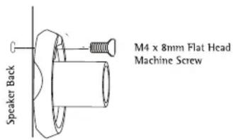
Figure 2
Single Hole Mounting
-
Most satellite speakers will require the use of the M5 x 20mm machine screw used in combination with the M5 x 1/8" plastic washer. The plastic washer is used as a spacer between the threaded insert and the post (Figure 1). NOTE: It is critical the M5 plastic washer is used correctly.
-
Once the proper configuration is determined, secure the post to the speaker.

Figure 3
-
Some speakers use the smaller M4 x 8mm hardware, which is inserted into the off-center hole on the mounting post (Figure 2).
-
Check the size of the hole and make sure the 5/8"-32x5/8" machine screw, the 1/4"-20 x 1/2" machine screw, the M6 x 20mm, or the M5 x 20mm fits inside (Figure 3).
-
When the correct size is determined, place the screw through the speaker post and attach to the rear of the speaker enclosure. NOTE: If the screw does not tighten properly, use the M5 x 1/8" plastic washer to tighten it up.
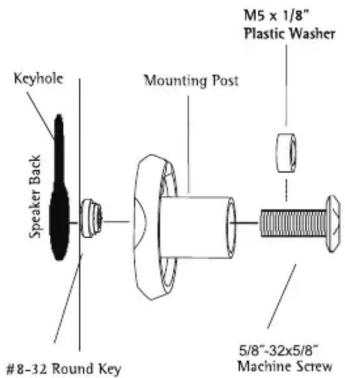
Figure 4
Key Hole Mounting
- If your speaker has a factory key hole design, you will use the 5/8"-32x5/8" machine screws in combination with the key hole nut.
- Loosely pre-assemble the mounting post with the 5/8"-32x5/8" machine screw and key hole nut (Figure 4).
NOTE: Be sure the key hole nut is installed with the knurled (rough) edge toward the post. - Engage the key hole nut into the key hole slot, as shown.
- Put tension on the assembly by gently pulling back on the speaker mount post while tightening the 5/8"-32x5/8" machine screw (Figure 4).
- The key hole nut will engage on the housing in the key hole slot.
- If the post does not tighten securely against the housing, it will be necessary to use the M5 x 1/8" plastic washer as a spacer under the head of the 8-32 x 5/8" machine screw (Figure 4).
2/4 - Hole Mounting
- Find the best mounting configuration that matches your speaker enclosure. Four-hole speaker mount patterns can be accommodated by positioning the speaker plate diagonally (Figure 5).
- Using the 1/4"-20 x 1/2" machine screws, install the speaker plate and secure the speaker enclosure (Figure 5).

2-Hole Orientation

4-Hole Orientation

Figure 5

Self-Tapped Mounting
- Locate the optimum location for the mounting plate and use it as a template to mark the drilling locations.
NOTE: Do not drill or screw into the speaker where you could possibly damage the internal components.
- Drill the pilot hole(s) using a 1/8" drill bit. This hole(s) should not be drilled more than 1/2" depth (Figure 6).
MOUNTING TO THE WALL OR CEILING
The mounting hardware for three different surface applications is supplied. You will need to determine what style hardware will work best with your mounting surface. Always use caution when drilling into a wall or ceiling. Make sure to avoid all electrical and water lines.
WOOD SURFACE
- Using a stud finder, locate the wood stud or framing member.
NOTE: Always mount the speakers in the center of a stud.
- Using the wall plate as a template, mark hole positions on mounting surface.
NOTE: Inwall mounting applications position mounting holes in a vertical pattern (Figure 7).
-
Drill holes through the drywall and into the wood stud using a 1/8" drill bit. These holes should be drilled 1-7/8" deep (Figure 7).
-
After the holes are drilled, mount the wall plate using the ST5.5x45 self tapping screws.

Figure 7

DRYWALL SURFACE
- Locate the best mounting location in the ceiling or wall. Using the wall plate as a template, mark the hole positions on the mounting surface.
NOTE: In wall mounting applications position mounting holes in a vertical pattern.
-
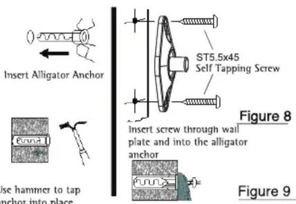
Drill holes in the drywall using a 5/16" drill bit (Figure 8).
-
Once the holes are drilled, insert the alligator anchor into the holes. Make sure the anchor is flush with the wall and/or ceiling surface (Figure 8).
-
With the anchors in place, mount the wall plates using the ST5.5x45 self tapping screws (Figure 8).
CONCRETE SURFACE
- Using the wall plate as a template mark a hole positions on the mounting surface.
NOTE: In wall mounting applications position mounting holes in a vertical pattern.
-
Drill holes in the solid concrete or hollow block using a 5/16" masonry bit. Once the holes are drilled, insert the #12-14 Alligator anchors (Figure 9) into the holes, making sure the anchor is flush with the surface of the wall (Figure 9).
-
With the wall anchors in place, mount the wall plate using the ST5.5x45 self tapping screws (Figure 9).
Extension Mounting
Ceiling and/or Shelf Applications
Do Not Use Extension In Wall Mounted Applications

Tighten the Allen screw using the provided Allen wrench
Figure 10
Install 2-1/2" extension portion of the speaker mount to the wall plate.
Secure the setscrew to hold the extension in place with the weight of the speaker attached.
Low-Profile Mounting
Wall and Ceiling Applications
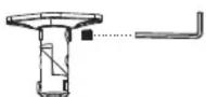
Tighten the Allen screw using the provided Allen wrench

Figure 11
Install the low-profile portion of the speaker mount to the wall plate or 2-1/2" extension. Secure the setscrew to hold the extension in place with the weight of the speaker attached.
Speaker Mounting
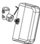

Post Style Speaker Plate 2-Hole Speaker Plate Figure 12
Install the speaker with the speaker post or 2-hole plate attached.
Secure the setscrew to hold the extension in place with the weight of the speaker attached.
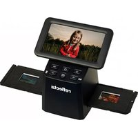
Brand : Reflecta
Model : 23182
Category : Speaker Stand